

Henderson Insulated Roller, Ansa RS1 Installation Instructions Manual

U.K. Customer Services Department
Telephone: 0191 377 1441 Facsimile: 0191 377 2972
E-mail: sales@pchenderson.com
Durham Road, Bowburn, County Durham DH6 5NG, England. Telephone: 0191 377 0701 Facsimile: 0191 377 1309
www.pchenderson.com
P C Henderson (Ireland) Ltd
West Link Industrial Estate, Kylemore Road, Dublin 10, Ireland. Telephone: 01626 0444 Fax: 01626 0455
www.pchenderson.ie E-mail: sales@pchenderson.ie
Declaration of Incorporation
This Declaration of Incorporation has been prepared by the garage
door manufacturer to signify that the accompanying garage door
operator, if installed in accordance with the manufacturer’s detailed
instructions will meet the requirements of EN12453.
It is the responsibility of the installer to ensure that doors and garage
door operators are correctly matched prior to installation.It is also the
responsibility of the installer, legally described as the Responsible
Person,to ensure that a suitably nominated person will confirm that the
power operated door has been installed in accordance with the
instructions provided by both the door and drive unit manufacturer.
It is also the responsibility of the installing company to check after
installation that the power operated door and any safety devices
provided are suitable for the application and are all working
satisfactorily.This will permit the nominated person to attach a CE label
identifying the name of the installing company, a unique door reference
number and a date of completion.The installing company should label
the door and provide the documentation as specified within EN12635.
One copy of the Declaration of Conformity is to be issued to the client
and one copy is to be retained by the installing company,together with
the relevant two Declarations of Incorporation. In accordance with the
requirements of the Machinery Directive and the UK Supply of
Machinery (Safety) Regulations, these records are to be retained on file
for a period of ten years.
Note.
Duplicated printed pads set out in the format of Declarations of
Conformity in order to allow on site completion are available at a
reasonable cost from the DSMA for both members and non-members.
Alternatively, for an additional cost, a technical records file with full
details of requirements and procedures for compliance, and including
the necessary filing divisions, is also available.
SUPPLY OF MACHINERY (SAFETY) REGULATIONS 1992
E.C. DECLARATION OF INCORPORATION
GARAGE DOORS FOR POWERED OPERATION
GARAGE DOORS • SLIDING AND FOLDING DOOR HARDWARE
COMPOSITE ENTRANCE DOORS
P.C. HENDERSON LIMITED, DURHAM ROAD, BOWBURN, DURHAM DH6 5NG.
March 2007 Issue 1 (Insulated Roller Garage Doors)
This declaration is made by:
(V.Brockley, Managing Director)
Installation Instructions
Insulated roller door and Compact insulated
roller door remote control unit
March 2007
Insulated Roller
Garage Doors
Ansa RS1 roller door remote control system
Contents
1 General description
2 Fitting the RS 1 control unit. .
3 Operation
3.2 Function of the red LED indicator.
4 RS1 Control board- overview.
5 Electrical connections.
6 Commissioning.
7 Fitting photoelectric safety sensor[s]
7.1 How to align the photoelectric beam[s]
7.2 Photoelectric sensor operation and testing
8 Adding transmitters.
9 Deleting transmitters
10 Dip switch Settings
11 Multi- door control
12 Photoelectric Cell Override
13 Fault diagnostic system.
14 Control inhibit feature.
15 Fitting the optional aerial.
16 Maintenance.
17 Problem solving guide
18 Technical specifications
1 - General Description
2 - Fitting the RS1 Control Unit
Built-in Light
Multi-function Red LED indicator
Operating button
Lugs
Cover
Spare main
board fuses
Trim
Cover screws
Base
The Ansa RS 1control unit is designed to operate roller garage doors fitted with single phase tubular motor drives. Equipped with “rolling code”
high security remote controls, allowing easy memorisation of up to fifteen transmitters.The unit has all the features needed for efficient, safe and
reliable operation of roller doors including built-on courtesy lamp, operating button and multi- function red indicator LED.
Installation instructions
Please read these instructions carefully prior to commencing installation of the unit. Operate unit only when the door is in full view
and free from any obstruction.No one should enter or leave the garage while the door is in motion.
2.1 The electric drive motor, RS1 control and photoelectric safety
sensor are normally fitted to the same side of the door opening.
Select a suitable position for the control unit,within sight of the door,
well away from moving parts, ensuring that :-
a. It can be plugged into an adjacent 13A switched socket.
b. It is within the constraints of the motor lead, using a 'tidy' cable run.
c. It is mounted with the built on lamp at the top.
d. It is fitted at a height of at least 1.6 metres out of the reach of children.
e. It is fitted inside a dry room only ( I.P.44 rating )
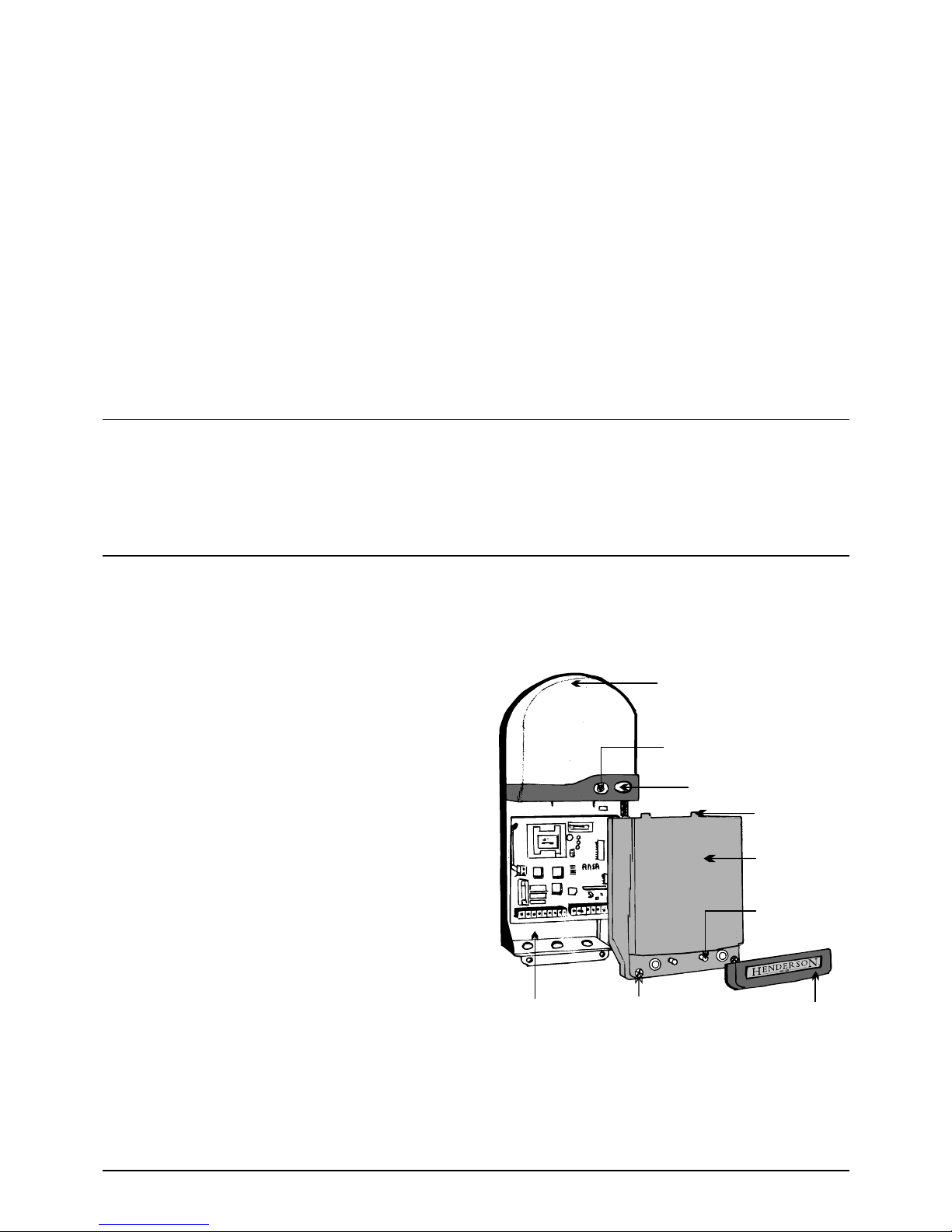
2.2 Fitting the enclosure - Refer to figure 1
Remove the courtesy lamp lens from the base by squeezing the sides
of the lens, disengaging the clip in the top of the lens. Remove any
packaging from the lamp. Pull off the trim, and undo the two fixing
screws approximately 8mm, noting that it is not necessary to
completely remove the screws which remain attached to the cover.
Carefully remove the cover by pulling away from the base with a slight
downward movement. The packing box provides a useful fixing
position guide, Fix the base to the wall using the fixing screws and
plugs provided.
Note: Do not allow dust to enter the unit which could
damage the electronics.
Figure 1
Motor run timer/auto close relay
Control fuse T500Ma
Open close & status buttons
Motor fuse T6.3A
Option dip switches
Test button
Link A
Code/de-code LED
Programming button
Operation - 3
3.1 The microprocessor control unit operates in sequential impulse
logic. The door can be operated using the test button, the operating
button fitted to the front of the control unit,the remote control hand set
or other optional controls connected to the system. Push any of the
above buttons and the door will open. Push a button again and the door
will close. If a button is pressed whilst the door is moving it will stop and
pushing the button again will reverse the original direction.
The advanced electronics monitor the motor drive and limit switches and
turn off the motor run timer as soon the door reaches a fully open or a
fully closed position.There is no need to wait for the run time to expire
before closing a recently opened door and accidentally operating the
photoelectric safety sensor will not affect a recently closed door.
3.2 Function of red LED indicator
Operation
Continuous on - Power is switched on [stand-by mode]
Flashing quickly - Safety input is active [e.g. photo- beam is obstructed]
Flashing slowly - Diagnostic self-test is active [Indicates fault in control
wiring , control device or photo-electric sensor].Door is inoperable until
the fault is corrected.
3.3 Courtesy lamp.
The courtesy light will switch on for four minutes whenever the door is
operated and turn off automatically.
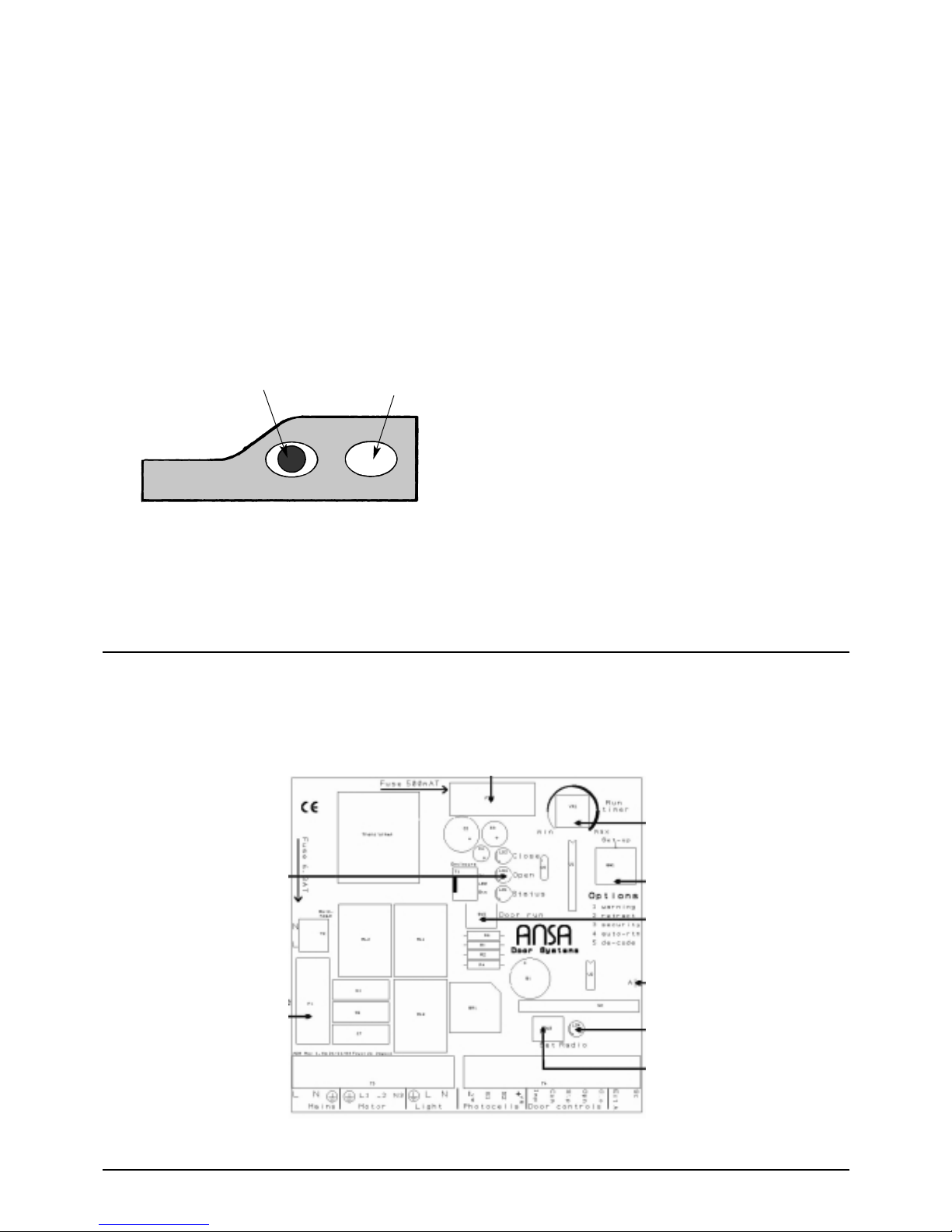
Control Board Overview - 4
Multi-function Red Indicator LED Operating button
Figure 2
 Loading...