

Henderson EVOLVE POCKET DOOR PRO Fitting Instructions Manual
KIT AND DOOR SPECIFICATION
Kit Short Code
Max. Door Height
Max. Door Width
Door Thickness Range
Max. Door Weight
EVOPRO1/***
1981mm (78”)
610mm (24”)
28 – 44mm
80kg
EVOPRO2/***
1981mm (78”)
686mm (27”)
28 – 44mm
80kg
EVOPRO3/***
1981mm (78”)
762mm (30”)
28 – 44mm
80kg
EVOPRO4/***
1981mm (78”)
838mm (33”)
28 – 44mm
80kg
EVOPRO6/***
2040mm (80”)
826mm (32.5”)
28 – 44mm
80kg
EVOPRO7/***
2040mm (80”)
726mm (28.5”)
28 – 44mm
80kg
EVOPRO10/***
2315mm (91”)
930mm (36.5”)
28 – 44mm
80kg
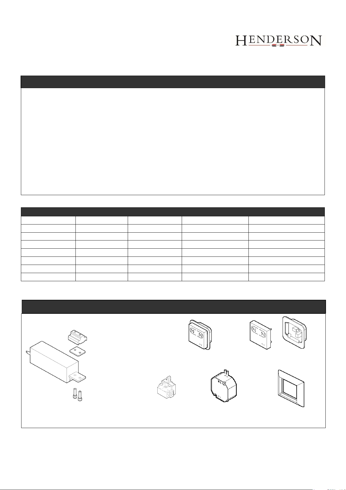
2 x Socket Surround
ELECTRICAL COMPONENTS
1 x Motor Connector
Block
1 x Motor Spacer
Plate
1 x Motor
2 x M6x25 Socket
Head Screw
1 x Wall Control
Socket
1 x Wall Socket &
1 x Cover Plate
1 x 24V Transformer
About this document
This document addresses qualified personnel only. The mounting must be done by technically educated, trained and qualified
personnel. Electrical wirings have to be completed by suitably qualified specialists.
These instructions describe how to install the track and sliding door hardware. For installation of the drive motor, switches or
sensors - please refer to the operating instructions for the Evolve Motor and Wiring Instructions.
The manufacturer’s specification must be respected in especially maximum weight restriction of door leaf. Any other use of
this product is considered inappropriate use.
It is not guaranteed that this product will work in conjunction with fittings, motors or other electronic devices supplied by other
manufacturers.
The appliance is only to be used with the power supply unit provided.
Before you commence work, please read through these instructions. Please store these instructions in a safe place and pass
them on to any future owners. Damage resulting from non-compliance with these instructions and safety instructions will void
the warranty. PC Henderson nor the motor unit manufacturer will assume liability for any consequential damage.
ABOUT THIS DOCUMENT
EVOLVE POCKET
DOOR PRO
Fitting Instructions
1 x Fused
Connector
*** For full short code replace with required finished wall thickness size – 120 or 125 (mm)
Note: If installing a liner kit with this kit please refer to Pocket Door Pro Liner Kit fitting instructions – this should be installed last.
1
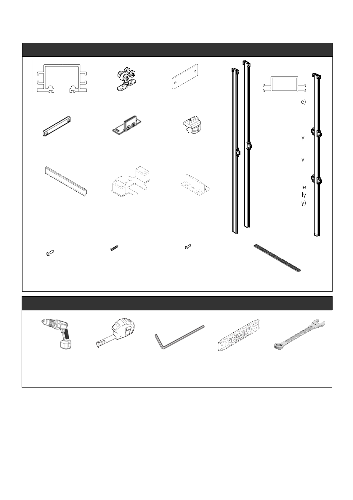
Screw B
4.2 x 25 Self tapping
8 x in EVOPRO 1, 2, 3, 4, 6, 7
24 x in EVOPRO10
Screw c
No 8 x 1” Woodscrew
18 x in EVOPRO 1-7
24 x in EVOPRO 10
KIT CONTENTS
1 x Header Track
2 x Hangers
4 x Fixing Plates
1 x SS Belt Clamp
1 x Toothed Belt Length
Noggin
2 x 395mm in EVOPRO1 & 2
2 x 545mm in EVOPRO3, 4, 6, 7
4 X 545mm in EVOPRO10
4 X 295mm EVOPRO10
Floor/Wall Bracket
2 x in EVOPRO1, 2, 3, 4, 6, 7
4 x in EVOPRO10
8 x Screw A
M6x20 Cap Head
Screws
Drill
With magnetic posi head driver
Tape Measure
5mm Allen Key
Spirit Level
6mm & 13mm Spanner
TOOLS REQUIRED
4 x 2.5mm spacer plate
125mm finished wall thickness
version only
Floor
Guide
102N
(Upright profile)
2 x Left Hand
Upright Assembly
2 x Right Hand
Upright Assembly
2 x Double
Upright Assembly
(EVOPRO10 only)
1 x Clamp and Pulley
Wheel
2
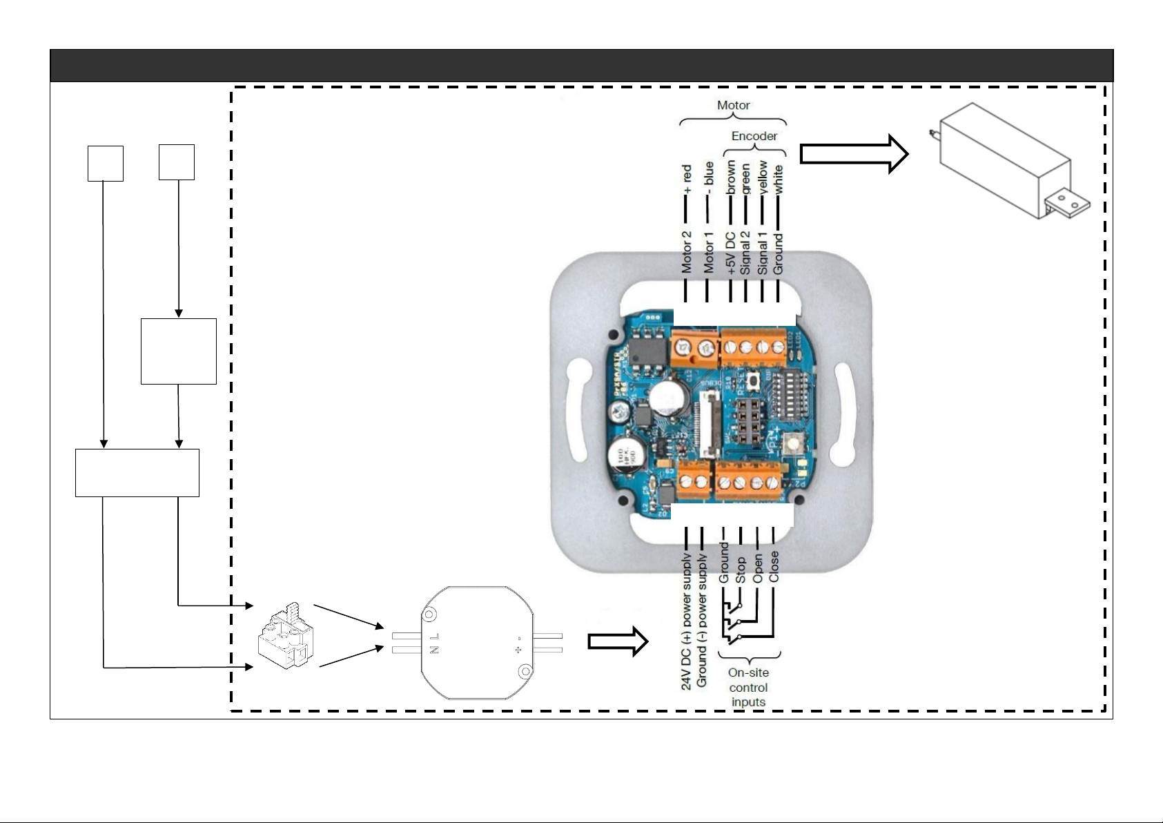
WIRING DIAGRAM OVERVIEW
All pole mains
switch (on site)
10A
(on site)
L
N
Fused Connector
Power Supply 24 V DC
Motor Unit
Electrical content supplied by PCH
b a 82 86 85 1
2 1 1 15 21 29
3

For detailed operation and programming instructions please consult separate Evolve Motor and Wiring Instructions
supplied.
1. Operation Mode Semi-Automatic/Automatic
When semi-automatic mode is set the drive will not close automatically - the potentiometer is without function.
When the automatic mode is set the drive closes automatically.
2. Dead Man’s Control
When dead man’s control is activated the drive will lonely operate, as long as an input is applied. Switch 1 is inactive
when dead man’s control is selected.
3. Push & Go
With push & go enabled the drive starts to move, as soon as the door is pushed manually.
4. Reaction on Obstruction
When reverse is set the drive stops and starts to move in the opposite direction as soon as an obstruction is
detected. If this isn’t set it will stop until a new command is given. This is only possible in semi-automatic mode.
5. Closing Speed
By default the closing speed is slower than the opening speed. The closing speed can be set as fast as the opening
speed, by setting this switch to ON>
6. Maximum Door Speed
The maximum speed has to be set via these switches
Maximum speed is dependent on the door weight according to DIN EN 18650
Weight of door is up to 80kg - maximum speed is 20cm/s
Weight of door is up to 80kg - maximum speed is 23cm/s
Weight of door IS up to 80kg - maximum speed is 26cm/s
When no switch is activated, the slowest speed is set (20cm/s)
When more than one switch is activated, a reduced speed is set (12 cm/s)
PERFORM RESET
1. Switch Power Supply On
Control device in delivery status or after power cut
Red LED blinks continuously twice with a short break of 1.5sec
2. Press RESET for About 2 Seconds
Red LED blinks continuously
3. Check Driving Direction of Motor with Control Keys
When pressing OPEN, door has to open and when pressing CLOSE, door has to close
When driving direction is wrong - swap motor cables (terminals MA and MB), check driving direction again.
4. Move Door in Middle Position by Pressing and Holding the Control Keys
5. Press RESET for About 2 Seconds
Red LED lights up permanently
Green LED lights up during motor activity
Door moves in the open position
Door moves in the closed position
Door moves in the open position
LED’s go out
CHECK FUNCTIONALITY
1. Test, if the door shows desired behavior
2. In case of malfunction check electrical connections and configurations
for electrical connection refer to chapter 5.3 of the Evolve Motor and Wiring Instructions supplied
for configuration refer to chapter 6.1 of the Evolve Motor and Wiring Instructions supplied
Repeat initial operation, if necessary
3. Initial operation is completed when function is correct
WIRING WALL MOUNTED SOCKET - OVERVIEW
5
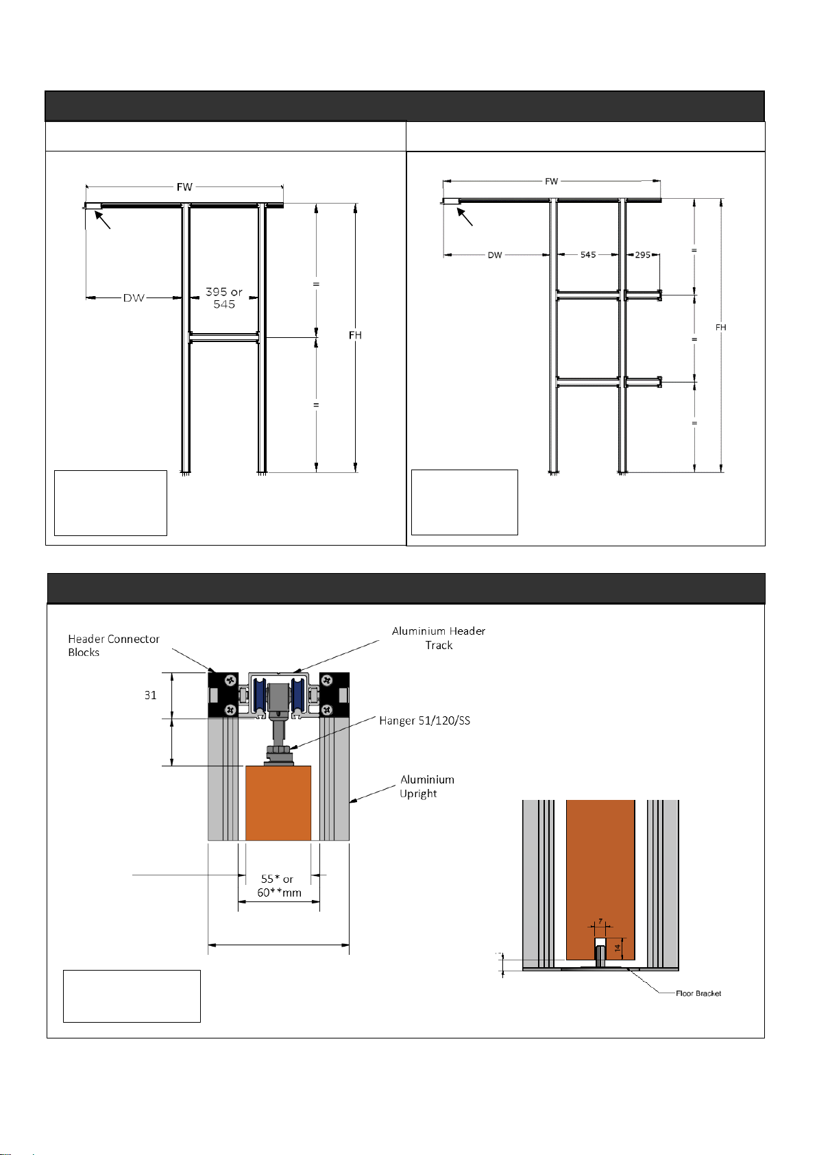
EVOLVE POCKET DOOR PRO KIT CONFIGURATION
EVO PRO 1, 2, 3, 4, 6 & 7
EVO PRO 10
NOTE
DW = door width
FW = frame width
FH = frame height
EVOLVE POCKET DOOR PRO HEADER & FOOTER DETAIL
NOTE
DW = door width
FW = frame width
FH = frame height
NOTE
*When using 120mm kit
** When using 125mm kit
32mm
Door Thickness
35 – 44mm
95* or 100**mm
MOTOR
ASSEMBLY
MOTOR
ASSEMBLY
5
5
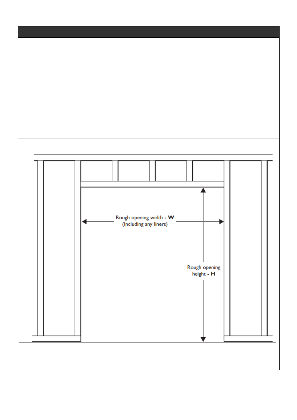
STEP 1: Prepare the rough opening
How to calculate the opening width required
Opening width in mm = (door width x 2) + 30mm (or 62mm if using with self-closing mechanism)
Opening height in mm = door height + 70mm
Note: 70mm allows for: door floor clearance (range 7 - 20mm) + top of door to bottom of track (range 19 - 32mm)
+ track height (31mm)
Finished Wall Thickness
Stud wall can be 95mm or 100mm plus plasterboard (2 x 12.5mm) e.g.
95mm cavity + 12.5mm plasterboard either side= 120mm finished wall thickness
100mm cavity + 12.5mm plasterboard either side = 125mm finished wall thickness
STEP BY STEP INSTRUCTIONS
6
 Loading...