


U.K. Customer Services Department
Telephone: 0191 377 1441 Facsimile: 0191 377 2972
E-mail: sales@pchenderson.com
Durham Road, Bowburn, County Durham DH6 5NG, England. Telephone: 0191 377 0701 Facsimile: 0191 377 1309
www.pchenderson.com
P C Henderson (Ireland) Ltd
West Link Industrial Estate, Kylemore Road, Dublin 10, Ireland. Telephone: 01626 0444 Fax: 01626 0455
www.pchenderson.ie E-mail: sales@pchenderson.ie
Declaration of Incorporation
This Declaration of Incorporation has been prepared by the garage
door manufacturer to signify that the accompanying garage door
operator, if installed in accordance with the manufacturer’s detailed
instructions will meet the requirements of EN12453.
It is the responsibility of the installer to ensure that doors and garage
door operators are correctly matched prior to installation.It is also the
responsibility of the installer, legally described as the Responsible
Person,to ensure that a suitably nominated person will confirm that the
power operated door has been installed in accordance with the
instructions provided by both the door and drive unit manufacturer.
It is also the responsibility of the installing company to check after
installation that the power operated door and any safety devices
provided are suitable for the application and are all working
satisfactorily.This will permit the nominated person to attach a CE label
identifying the name of the installing company, a unique door reference
number and a date of completion.The installing company should label
the door and provide the documentation as specified within EN12635.
One copy of the Declaration of Conformity is to be issued to the client
and one copy is to be retained by the installing company,together with
the relevant two Declarations of Incorporation. In accordance with the
requirements of the Machinery Directive and the UK Supply of
Machinery (Safety) Regulations, these records are to be retained on file
for a period of ten years.
Note.
Duplicated printed pads set out in the format of Declarations of
Conformity in order to allow on site completion are available at a
reasonable cost from the DSMA for both members and non-members.
Alternatively, for an additional cost, a technical records file with full
details of requirements and procedures for compliance, and including
the necessary filing divisions, is also available.
SUPPLY OF MACHINERY (SAFETY) REGULATIONS 1992
E.C. DECLARATION OF INCORPORATION
GARAGE DOORS FOR POWERED OPERATION
GARAGE DOORS • SLIDING AND FOLDING DOOR HARDWARE
COMPOSITE ENTRANCE DOORS
P.C. HENDERSON LIMITED, DURHAM ROAD, BOWBURN, DURHAM DH6 5NG.
March 2007 Issue 1 (Insulated Roller Garage Doors)
This declaration is made by:
(V.Brockley, Managing Director)
Installation Instructions
Insulated roller door and Compact insulated
roller door remote control unit
March 2007
Insulated Roller
Garage Doors
Ansa RS1 roller door remote control system
Contents
1 General description
2 Fitting the RS 1 control unit. .
3 Operation
3.2 Function of the red LED indicator.
4 RS1 Control board- overview.
5 Electrical connections.
6 Commissioning.
7 Fitting photoelectric safety sensor[s]
7.1 How to align the photoelectric beam[s]
7.2 Photoelectric sensor operation and testing
8 Adding transmitters.
9 Deleting transmitters
10 Dip switch Settings
11 Multi- door control
12 Photoelectric Cell Override
13 Fault diagnostic system.
14 Control inhibit feature.
15 Fitting the optional aerial.
16 Maintenance.
17 Problem solving guide
18 Technical specifications
1 - General Description
2 - Fitting the RS1 Control Unit
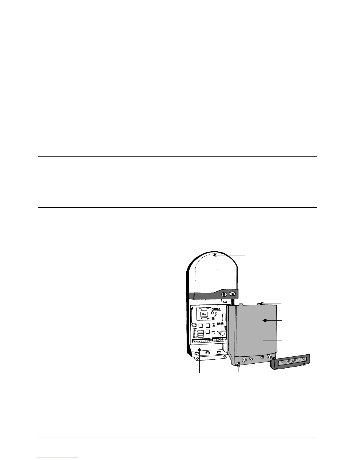
Built-in Light
Multi-function Red LED indicator
Operating button
Lugs
Cover
Spare main
board fuses
Trim
Cover screws
Base
The Ansa RS 1control unit is designed to operate roller garage doors fitted with single phase tubular motor drives. Equipped with “rolling code”
high security remote controls, allowing easy memorisation of up to fifteen transmitters.The unit has all the features needed for efficient, safe and
reliable operation of roller doors including built-on courtesy lamp, operating button and multi- function red indicator LED.
Installation instructions
Please read these instructions carefully prior to commencing installation of the unit. Operate unit only when the door is in full view
and free from any obstruction.No one should enter or leave the garage while the door is in motion.
2.1 The electric drive motor, RS1 control and photoelectric safety
sensor are normally fitted to the same side of the door opening.
Select a suitable position for the control unit,within sight of the door,
well away from moving parts, ensuring that :-
a. It can be plugged into an adjacent 13A switched socket.
b. It is within the constraints of the motor lead, using a 'tidy' cable run.
c. It is mounted with the built on lamp at the top.
d. It is fitted at a height of at least 1.6 metres out of the reach of children.
e. It is fitted inside a dry room only ( I.P.44 rating )
2.2 Fitting the enclosure - Refer to figure 1
Remove the courtesy lamp lens from the base by squeezing the sides
of the lens, disengaging the clip in the top of the lens. Remove any
packaging from the lamp. Pull off the trim, and undo the two fixing
screws approximately 8mm, noting that it is not necessary to
completely remove the screws which remain attached to the cover.
Carefully remove the cover by pulling away from the base with a slight
downward movement. The packing box provides a useful fixing
position guide, Fix the base to the wall using the fixing screws and
plugs provided.
Note: Do not allow dust to enter the unit which could
damage the electronics.
Figure 1
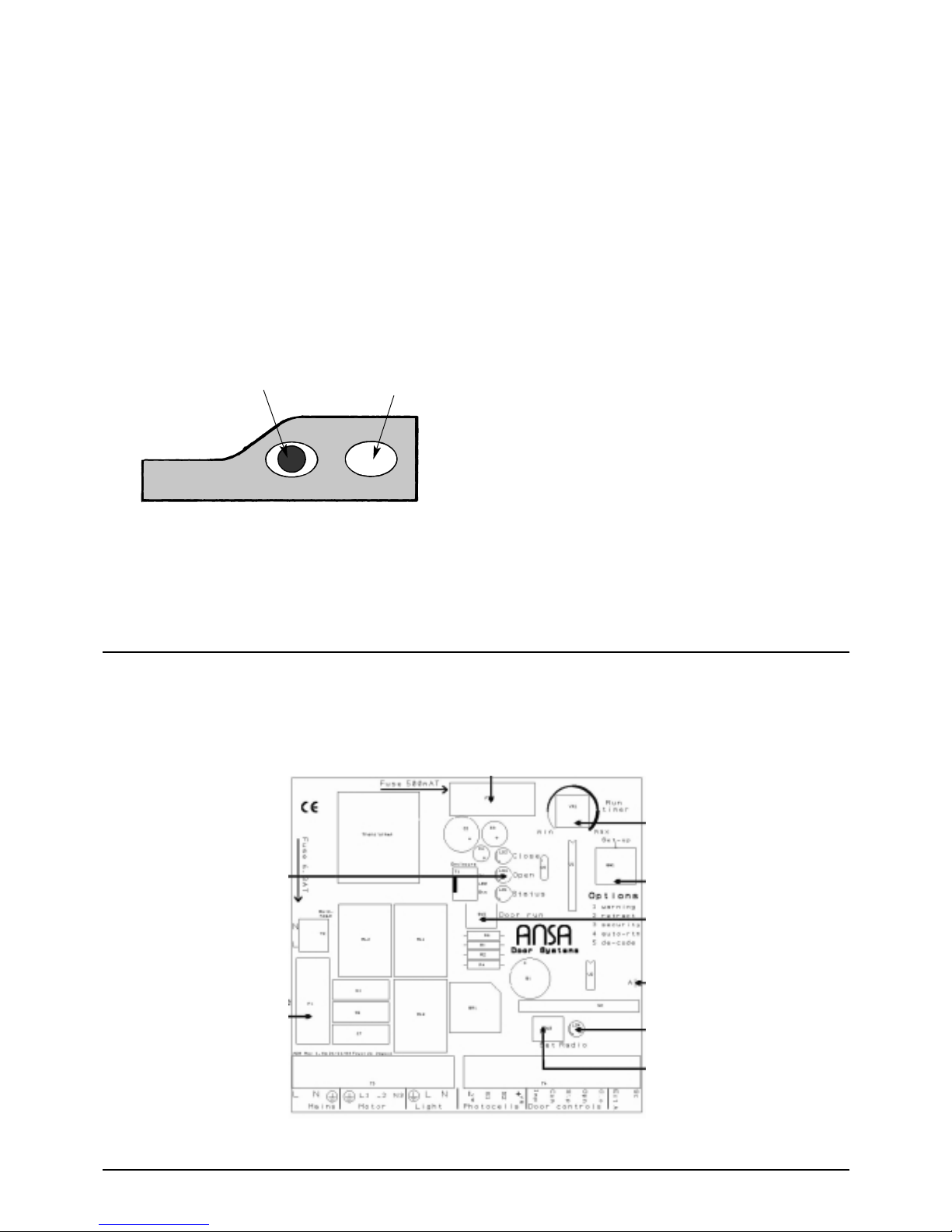
Motor run timer/auto close relay
Control fuse T500Ma
Open close & status buttons
Motor fuse T6.3A
Option dip switches
Test button
Link A
Code/de-code LED
Programming button
Operation - 3
3.1 The microprocessor control unit operates in sequential impulse
logic. The door can be operated using the test button, the operating
button fitted to the front of the control unit,the remote control hand set
or other optional controls connected to the system. Push any of the
above buttons and the door will open. Push a button again and the door
will close. If a button is pressed whilst the door is moving it will stop and
pushing the button again will reverse the original direction.
The advanced electronics monitor the motor drive and limit switches and
turn off the motor run timer as soon the door reaches a fully open or a
fully closed position.There is no need to wait for the run time to expire
before closing a recently opened door and accidentally operating the
photoelectric safety sensor will not affect a recently closed door.
3.2 Function of red LED indicator
Operation
Continuous on - Power is switched on [stand-by mode]
Flashing quickly - Safety input is active [e.g. photo- beam is obstructed]
Flashing slowly - Diagnostic self-test is active [Indicates fault in control
wiring , control device or photo-electric sensor].Door is inoperable until
the fault is corrected.
3.3 Courtesy lamp.
The courtesy light will switch on for four minutes whenever the door is
operated and turn off automatically.
Control Board Overview - 4
Multi-function Red Indicator LED Operating button
Figure 2

Always switch off the mains power supply before making any connections!. Electrical connections should be carried out by a
competent person, if in doubt consult a qualified electrician!
Cables should enter the control unit through the cable glands fitted to the bottom of the RS1 unit.
5.1 POWER - The 240v A/C input should be connected from an adjacent 13 amp 3 pin switched socket.The plug must be fitted with a 5 amp fuse.
Connect to terminals marked L, N, E, MAINS
5.2 MOTOR - Connect the motor lead to the terminals marked E,L1,L2 N3 MOTOR. The blue motor neutral cable must be connected to the
terminal marked N3.Connect the yellow/green earth cable to the terminal marked E.Connect the brown and black motor power cables to terminals
L1 & L2. Ensure that motor direction matches the open and close LED’S if necessary interchange the motor cables at terminals L1 & L2.
5.3 ADDITIONAL LIGHTING - Terminals marked LIGHT, E, L, N, provide a 240 volt ac output which functions the same as the built on light.
Lighting switches on for 4 minutes whenever the door is operated and turns off automatically. Maximum load 200 watts. The output should be
connected to a class 2 double insulated luminaire.
5.4 PHOTOELECTRIC SAFETY BEAM - ANSA RS1 can be connected to one or two photoelectric sensors which must be capable of
operating from a 24v DC supply voltage,and must have a normally closed NPN output signal.If two photocells are used they should be the same type.
OPERATION - The safety beam has no effect on an opening door. Breaking the safety beam prevents closure of an open door, and will also stop
and re-open a closing door.
CONNECTING A SINGLE PHOTOELECTRIC CELL - Remove the factory fitted ling connecting -VE & S1.The supply to the photocell is
connected to the terminals marked -VE & +VE. Connect the output signal to terminal S1, (retain the link connecting S1 & S2).
CONNECTING TWO PHOTOELECTRIC CELLS - Remove the factory fitted ling connecting -VE & S1 and S1 & S2. The supply to the
photocell is connected to the terminals marked -VE & +VE.Connect the output signal from the first sensor to terminal S1. Connect the output signal
from the second sensor to terminal S2.
5.5 OPTIONAL DOOR CONTROLS - A wide range of additional door controls may be connected to the unit, i.e. key switches, push buttons,
digital key pads etc.
IMPULSE DEVICE - A push to make (normally open) push button or key switch can be connected to terminals COM & IMP, this provides an
OPEN - STOP - CLOSE - STOP sequential operation.
STOP PUSH BUTTON - A push to break (normally closed) push button or key switch can be connected to terminals marked COM & STP.
Activation will stop the door immediately regardless of it’s position. If used remove the factory fitted link connecting COM & STP.
DOOR OPEN DEVICE - A push to make (normally open) push button can be connected to terminals COM & OPN. Operation will open the
door or re-open a closing door.
DOOR CLOSE DEVICE - A push to make (normally open) push button can be connected to terminals COM & CLO.To provide a door close signal.
5 - Electrical Connections

Commissioning - 6
6.1 If possible, manually operate the door and position the door curtain half open. Switch on the mains power supply and check that the multi-
function red LED is on.The on board status L.E.D should be illuminated green.
6.3 Adjust the motor limit switches.
Carefully adjust the limit switches following the door manufacturer's instructions. For screw adjuster type limits turn on Dip switch 3. Press the
operating button and ensure that the motor direction matches the open and close circuit board LED'S, if necessary switch off the mains power
supply and interchange the motor cables at L1 and L2.
Note-the motor unit has an inbuilt thermal trip which activates if the motor gets too hot after repetitive use, causing the motor to cut out. If the
thermal trip operates wait approximately 10 minutes for the motor to return to normal operating temperature
When the limit switches are correctly set turn off Dip switch 3 for normal operation.see fig 4
NOTE: Connections shown are for left hand
motor installations. For right hand, swap brown &
black motor cables
Figure 4 - Connection diagram - Set up and testing
Figure 5 - Connection diagram - Remote control with photo cell unit
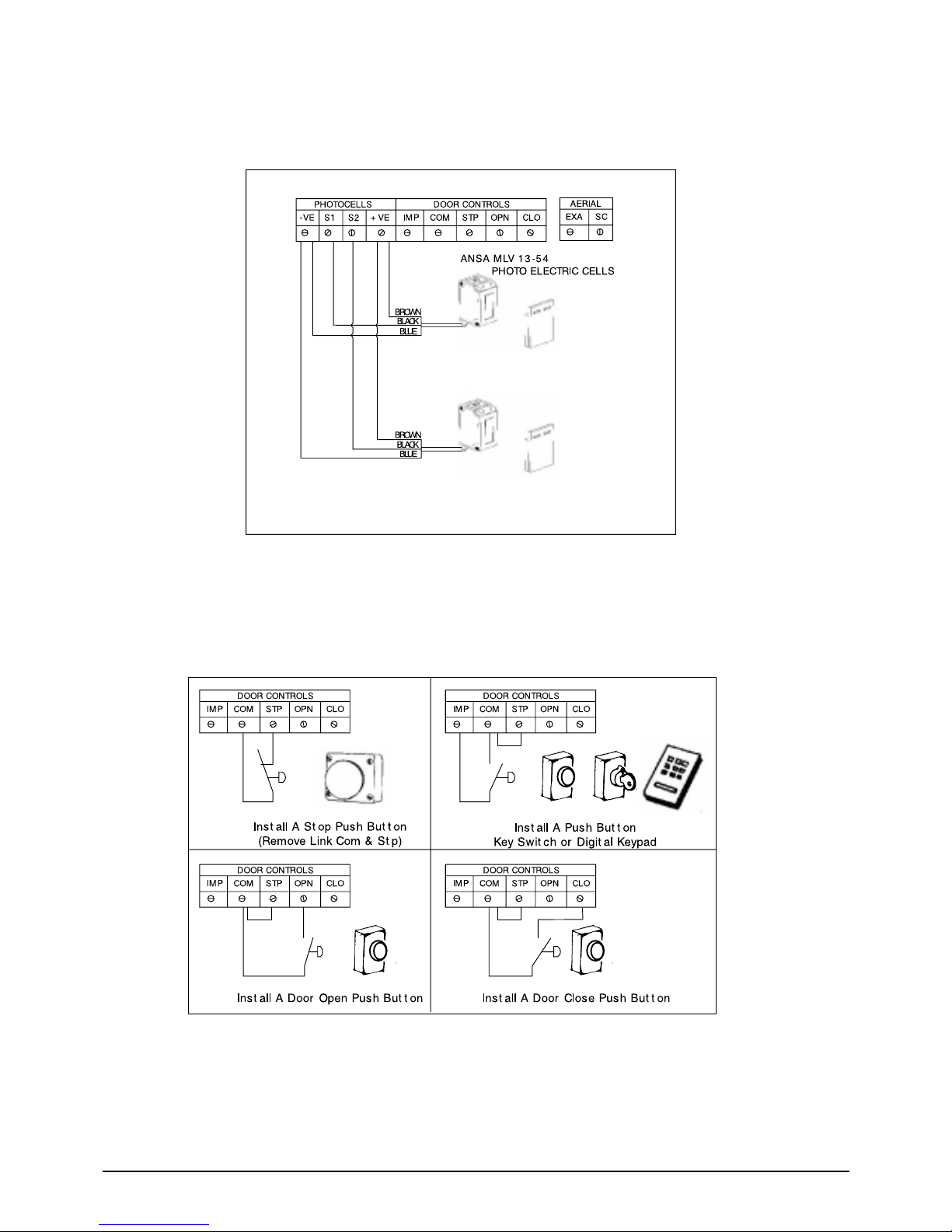
Figure 6 - Connection diagram - Installing 2 photoelectric cell units
Figure 7 - Connection diagram - Option controls

Fit the Photoelectric Safety Sensor - 7
Refer to figure 8.
Fix the photo cell brackets to the door guides at a recommended height of 300mm using the self-drilling screws provided. Fit the photoelectric
sensor to the pivot bracket using 2No M3 x 25mm nuts and bolts provided ensuring that the flat and shake proof washers are correctly fitted.
Attach the pivot bracket to the photocell bracket using 2No M4 x 15mm nuts and bolts provided.Fit the photocell reflector to the opposite bracket
using 2 No M4 x15mm nuts and bolts provided.
The diagram shows a right hand installation.The photo sensor can be fitted left hand using a similar assembly.
Note: the diagrams show the standard assembly, for extra wide doors, doors fitted with mechanical stops to the bottom rail or doors subject to
high wind pressure it is possible to turn the pivot bracket around which conveniently sets the photoelectric sensor slightly further away from the
door curtain.
7.1 How to align the photoelectric sensor(s) [ Ansa Type MLV 13/54 ]
The green L.E.D is illuminated when the photoelectric cell is switched on. For reliable operation it is important that the photo beam is “centred”
on the reflector using the following set-up procedure:Adjust fixing screws A & B so that the photoelectric sensor and pivot bracket can be moved
up and down and left to right. Move the sensor until the yellow L.E.D illuminates. Carefully move the pivot bracket left and right to obtain reference
points where the yellow L.E.D goes out. Set the pivot bracket in the mid position and tighten screws A.
Now similarly move the sensor up and down again noting the reference points where the yellow L.E.D goes out. Set the sensor in the mid position
and tighten screws B.
With the photocell correctly adjusted and working the green and yellow L.E.D's fitted to the sensor and the red indicator L.E.D fitted to the control
unit will be illuminated. Breaking the photo-beam will switch off the yellow L.E.D fitted to the sensor and cause the red indicator L.E.D to flash
quickly, confirming correct operation.
7.2 Photoelectric Sensor Operation And Testing
The safety beam has no effect on an opening door. Breaking the safety beam prevents closure of an open door and will also stop and re-open a
closing door.
The ADS v1.1 software fitted to the RS 1 control unit continuously monitors the photoelectric sensor. If a fault is detected the system prohibits
closure of the door.
Figure 8

8 - Adding Transmitters
To add extra transmitters
Press the operating button for 5 seconds and release when the red LED indicator goes out.The LED will flash once to confirm Add
Mode.Take the new transmitter to be added and press the button once.The red LED indicator should flash once. Repeat this for every
new transmitter to be added to the system. After the last transmitter has been added either wait 30 seconds or press the operating
push button once to reset to normal operation.
The remote control system uses the latest “rolling code” technology. Hand transmitters supplied are pre-programmed.The receiver can
memorise the codes of 15 transmitters. Upgrade memory chips are available for 31 or 62 transmitters by special order.
9 - Deleting Transmitters
It is not possible to selectively delete transmitters and selecting delete mode will erase all transmitters from the system. Switch off the
power supply to the unit and remove the front cover. Turn on Dip switch 5 and re-power the unit.The circuit board mounted yellow
“set radio” LED will illuminate for 5 seconds, all transmitters are now deleted. Switch off the power supply , turn off Dip switch 5 and
re-fit the front cover.Transmitters can now be reloaded using the “Add Transmitters“ procedure.
10 - Dip Switch Settings
The RS1 control unit has five onboard Dip switches which control the following features.
10.1 Dip switch 1 warning. When switched on, the courtesy light will flash three times before the door moves.
10.2 Dip switch 2 Retract. When switched on, selects partial retract. If the photocell is activated the door retracts 200mm instead of
returning to the fully open position.
10.3 Dip switch 3 Security. When switched on, extends the motor supply feed for the duration of the motor run timer which assists
adjustment of screw type motor limit switches Dip switch 3 is normally turned off.Additionally for doors having an externally fitted
manual override system, switching on Dip switch 3 selects a security system. If the manual override system is used to force open the
door, the system will power down the door to the closed position.
Note- When using the security system it is important to accurately set the motor run timer. operate the door from the fully closed to
the fully open position and adjust the run timer so that the circuit board “open” LED goes out five seconds after the door arrives at the
fully open position. See Fig 9.
10.4 Dip switch 4 Auto- Close. This option is normally turned off. Turning on Dip switch 4 selects an automatic time delay self
closing function.The time delay begins when the door is fully open and is reset if the photoelectric safety beam is broken.The auto-close
delay is dependant upon door size and operating speed. Set the motor run timer as described in “security”, the corresponding auto close
delay is shown in Fig 9.
Note ;Selecting Auto-close increases the level of automation and to comply with relevant safety standards we recommend the installation
of additional safety devices ie, safety edge system or additional photoelectric sensor.
10.5 Dip switch 5 Decode
Used when removing lost or stolen transmitters from the receiver memory. [see 9 Deleting Transmitters.]
Figure 9 - Run Timer Settings

Three types of transmitters are available, 1, 2 or 3 buttons, therefore up to three doors each fitted with a standard RS 1 control unit can
be controlled independently using a single transmitter. Simply select the transmitter button you wish to use with a particular door and
programme the transmitter as per section 7 “Adding Transmitters”.
16.1 Safety reverse check ;-Once a month check the system for correct operation. Using a transmitter or the operating button open
the door, stand inside the garage, close the door and whilst it is moving block the photo beam (using a piece of cardboard or similar)
The door should stop and then reverse either partially or to the fully open position depending on Dip switch 2 setting.The red LED
indicator should flash quickly when the photocell is blocked.
16.2 Keep the photo sensor lens and reflector clean using a soft damp cloth.
16.3 Keep the RS1 control unit and lens clean, occasionally wipe with a soft damp cloth.
.
The circuit board incorporates a built on aerial for the remote control receiver which is ideal for most applications.
15.1 An optional aerial is supplied which can be fitted as follows: Pass the 135mm stainless steel wire aerial through the small hole in
the base of the RS1 control unit and connect to the terminal marked “EXT A”. Snip the wire link marked “A” on the circuit board, this
is located on the right hand side of the board just above the receiver card.[see Fig 3]
15.2 It is also possible to fit a 'remote' aerial. Connect via coax cable with the inner to terminal “EXT A” and the screen to terminal
“SC”, again snipping link “A”[see Fig 3]
In some instances it may be helpful to switch off the controls operating the door temporarily without turning off the mains power supply
or erasing transmitter security codes. [For example during holiday periods].To activate this feature simply press and hold the operating
button for approximately 12 seconds and wait until the red indicator LED flashes slowly. To return to normal operation switch off the
power supply to the control unit for five seconds and then switch back on.
The microprocessor monitors the circuit board , low voltage control wiring,control devices connected to the system and photoelectric
sensor[s] and detects possible faults. If a fault is detected the door cannot be operated and the red LED will flash slowly. The power
supply should be switched off until the fault is found and corrected
If the safety input is active, the system automatically switches to “Photoelectric Cell Override Mode” which enables controlled closure of
the door in “dead-man” operation. Using a hand transmitter or the built-on operating button and with the door in full view press and
continue to hold the button.The red LED indicator will change state from flashing to on.The button is monitored and after five seconds the
door will close in “deadman” control. Releasing the button will stop the door and the above procedure can be repeated to continue closing
the door Activation of the safety circuit is indicated by the red LED which will flash quickly, this could be due to;- A loose or poor connection
to terminals -Ve, +Ve , S1 or S2. A dirty photocell sensor lens or reflector.. Poor alignment of the photoelectric sensor and reflector.
Multi-door Control - 11
Photoelectric Cell Overide - 12
Fault Diagnostic System.
- 13
Control Inhibit Feature.
- 14
Fitting the Optional Aerial.
- 15
Maintenance.
- 16

17 - Troubleshooting Guide
Note ;Always switch off the power supply before attempting to repair the door or control system.!
Faulty operation -- Red indicator LED is off - see 17.1.
Faulty operation -- Red indicator LED is on - see 17.2
Faulty operation -- Red indicator LED is flashing quickly - see 17.3
Faulty operation -- Red indicator LED is flashing slowly - see 17.4
Remote control transmitter problems - see 17.5
17.1 Faulty operation, the Red indicator LED is off. This indicates a power failure problem.
Check the power supply is live at the socket outlet.
Check the fuse in the 13a plug and fit a new 5A fuse if necessary.
Check both control board fuses, spares are supplied, fitted to the control unit cover. The main PCB fuse is a T 5 A 250 V [dia 5 mm x
20 mm , --see Fig 3]. The control PCB fuse is a T 500 Ma 250 V [dia 5mm x 20 mm , -- see Fig 3]
Check the security of the mains power cable at terminals L,N and E. If no fault is found, repair or replace the control board.
17.2 Faulty operation, the Red indicator LED is on. This indicates a possible problem with the motor drive.
Temporarily switch on and check the control board status LED -- if this is green:- The motor thermal trip may have operated.wait ten minutes
for the motor to cool down. Switch off and check the security of the motor cables at terminals E,L1,L2 and N3.
Check the motor drive and limit switches.If the control board status LED is red ;- Check the security of the link wire interconnecting terminals
Com & Stp [if fitted]. If a stop control device is fitted, check the operation and condition of cables connecting this to terminals Com & Stp.
17.3 Faulty operation , the Red indicator is flashing quickly. This indicates that the safety circuit is active.
Clean the photoelectric sensor and reflector.
Check the alignment of the safety beam.
Check the condition of cables connecting sensor[s] to terminals Ve, +Ve, S1 & S2. If a single photoelectric sensor is fitted check the
security of the link interconnecting terminals S1 & S2.
Operate the door using the photocell override procedure see section 12 and if necessary renew a damaged sensor or reflector.
17.4 Faulty operation , the Red indicator is flashing slowly. This indicates that the self-test diagnostic circuit has activated.
Check that terminals Com & Stp are interconnected using a link wire or stop push button before switching the mains power supply on.
Check that operating button next to the Red LED “clicks” when pressed.
Check for short circuits in any control devices or cables connected to terminals Com, Imp, Opn and Clo. [if fitted].
The photoelectric sensor may be faulty disconnect sensor[s] and temporarily bridge terminals -Ve & S1 and S1& S2.
Switch off the power supply for 5 seconds and re-power the unit to reset the system. If no fault is found, repair or replace the control
board.
17.5 Remote control transmitter problems.
The red LED on the hand set should illuminate when the button is pressed, if it does not- replace the battery in the transmitter. If the
LED is dim the battery is low and the operating range will be reduced.

INSTALLATION DETAILS
Installation Address;
Installed By;
Company;
Date;
Tel No;
SERVICE HISTORY
Date; Engineer; Comments;
Date; Engineer; Comments;
Date; Engineer; Comments ;
Date; Engineer; Comments;
Date; Engineer; Comments;
Technical Specification- 18
Supply Voltage 220-240 VAC
Transformer Power 3 VA
Power Relays 12 A - @ 230 VAC
Operating Temperature -15 to +55 deg.C
Enclosure Rating IP 44
Courtesy light 40 watts maximum.
Accessory Power Supply 24VDC --150 Ma
Control Logic Eeprom microprocessor.
Safety Input NPN
Frequency 433.92 Mhz
Security-Rolling Code Keeloq.
Dimensions 300mm H x 130mm W x 74mm D
 Loading...