

Page 1

OC-F08
Fixed gas detector
Operating Manual
Henan Oceanus
Page 2

Notice:
1、The personnel for operating and testing the gas detector should
firstly read the Operating manual. Only when according to our company
operating manual to use the gas detector, the device could normally
work.
2、If repair the gas detector or replace the parts, should be operated
by the professional guidance.
3、If users repair the gas detector or replace some parts not
according to our manual, our company will not be responsible for the
maintenance.
4、Explosion proof film and the Waterproof breathable film should
be cleaned or replaced regularly, or will affect the measuring sensitivity.
5、The usage of our company gas detector also should be according
to the rules of related department.
6、Fixed gas detector should be calibrated 6 months; but for some
sensor, we suggest calibrate every 3 months.
7、The sensor is the core parts of gas detector, if the detecting
environment with heavy smoke, humidity, dust, etc, please firstly do the
filtering pretreatment, then connect the gas detector , or will damage the
sensor.
8、For the Electrochemical sensor gas detector, please not expose it
in high gas concentration environment, this will reduce the sensor
working life or make the sensor poisoning.
9、If testing the gas in pipeline, please control the flow rate between
160~250ml/min, or the measurement will not stable.
一、Description:
OC-F08 fixed gas detector designed with the original imported
sensor, Catalytic combustion sensor for combustible gas,
1
Page 3
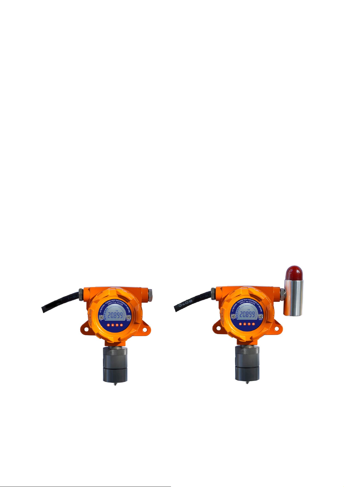
Electrochemical sensor for the Oxygen and Toxic gas, NDIR infrared
sensor for the Carbon Dioxide gas and Methane, PID sensor for the
VOCs. Designed with the dashboard display interface and three color
backlight; Data, fault, alarm display directly; Circuit board with four
layer wiring, also with the explosion proof design; Signal output
optional of the 4~20mA, RS485, 0~5V, 0~10V, 200~1000Hz, relay
output; Available for the DCS, PLC, or our control system; With high
sensitivity, quick response, high anti-interference, stable signal.
OC-F08 series fixed gas detector could be used for many
applications, including of the petroleum refinery, chemical plants, LPG
station, boiler room, gas station, paint spray booth, and other place need
to inspection safety.
1.1、Structural
2
Page 4

1.2、Safety notice
Higher or lower Oxygen concentration both will affect the
combustible gas inspection data.
The atmospheric pressure mutation will affect the O2 gas detector
data.
The vapor of silicone compound will damage the Catalytic
combustion sensor, so please the detecting environment no this
compounds.
In the process of usage, please keep the air inlet clean, or will display
lower data.
Please do not disassemble.
Please not put gas detector under the high temperature and humidity,
also the strong static electric place.
Please not use any corrosive liquid to clean the parts of gas detector.
The shell should be earthed reliably
If need to replace any parts, please contact manufacturer to solve the
fault.
The installation, operation and maintenance should be according to
the manual, GB3836.13-1997, GB3836.15-2000, GB3836.16-2006,
GB50257:1996.
3
Page 5
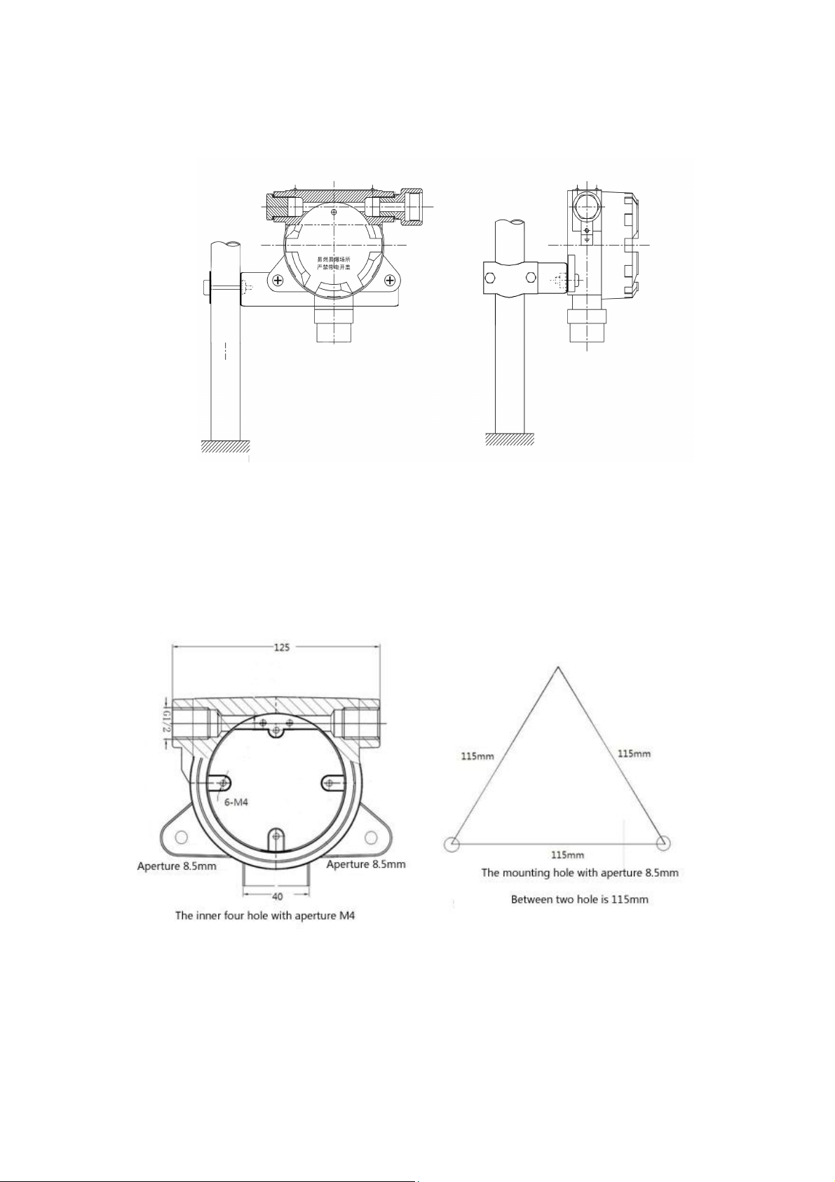
二、 Installation
A. Site installation
B . Installation and size
4
Page 6
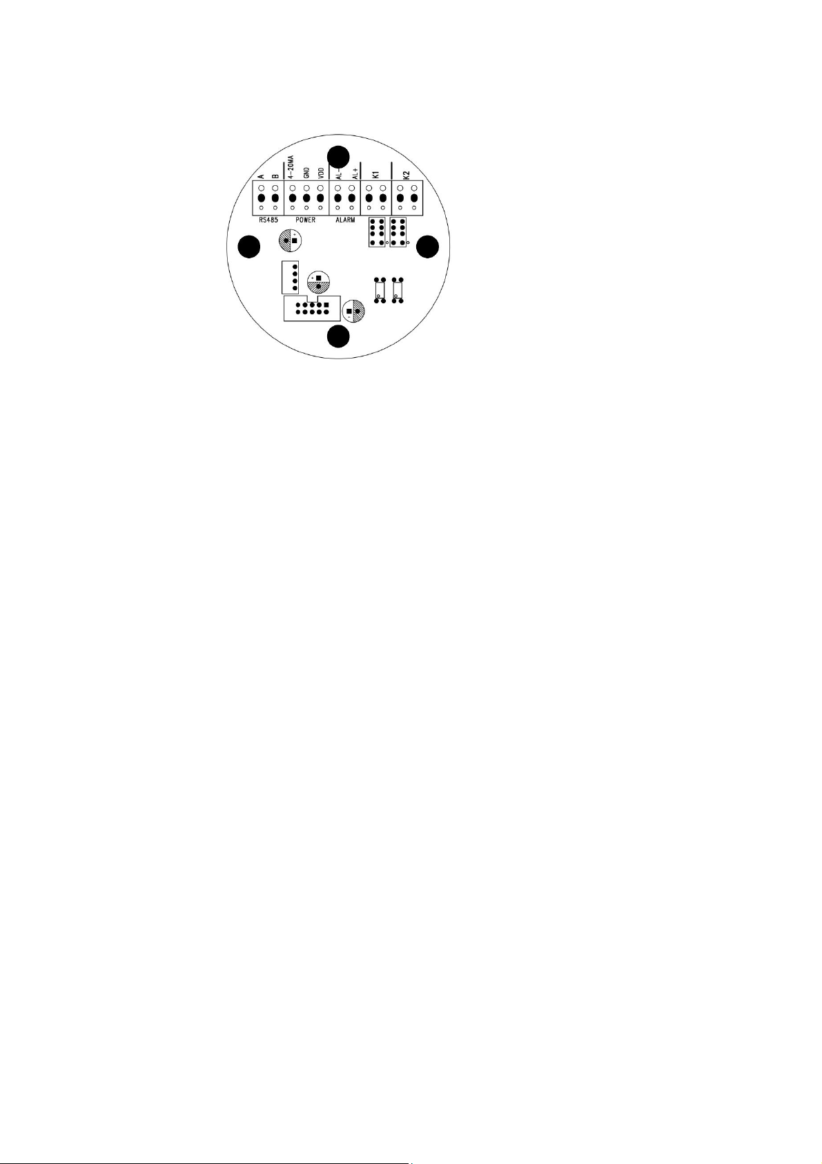
2.0、Internal connection:
C. Internal connection
From left to right the terminal is:
1、 “RS485” is RS-485 interface:“A” “B” are RS-485signal A
and signal B。
2、 “POWER” and 4~20mA output interface:“4~20mA” is
4~20mA signal output,“VDD” is 24V positive terminal, “GND”
is 24V negative terminal;
3、 “ALARM”: connect with 24V audible-visual alarm,if
choose the 200~1000Hz frequency signal, it could be frequency
output interface.
4、 “K1” is relay output:Grade-I alarm interface, when the signal
up to Grade-I value, relay K1 will act and control fan or other
equipments.
5、 “K2” is relay output:Grade-II alarm interface, when the
signal up to Grade-II value, relay K2 will act and control fan or
other equipments.
5
Page 7

2.1、Choose the installation position:
The installation position is very important, this should consider the
following factors: the leakage gas density, gas proportion, surrounding
buildings, wind direction, if indoor, also the position of the door and
window.
Our engineer offer the following suggestion:
If the detected gas heavy than air, the position should from ground
about 0.3~0.6m, if light than air, should higher the leakage source
than 0.5~2m.
The gas detector should keep right distance from leakage source, if
too close, when the leakage frequency, will get too many alarm data,
if too far, the gas detector will respond slowly.
When installed indoor, if the leakage source outdoor, the gas detector
should be installed in the air inlet position.
The gas detector quantity should be according to the detecting
environment.
The gas detector will be effected by the excessive temperature and
too low temperature.
6
Page 8
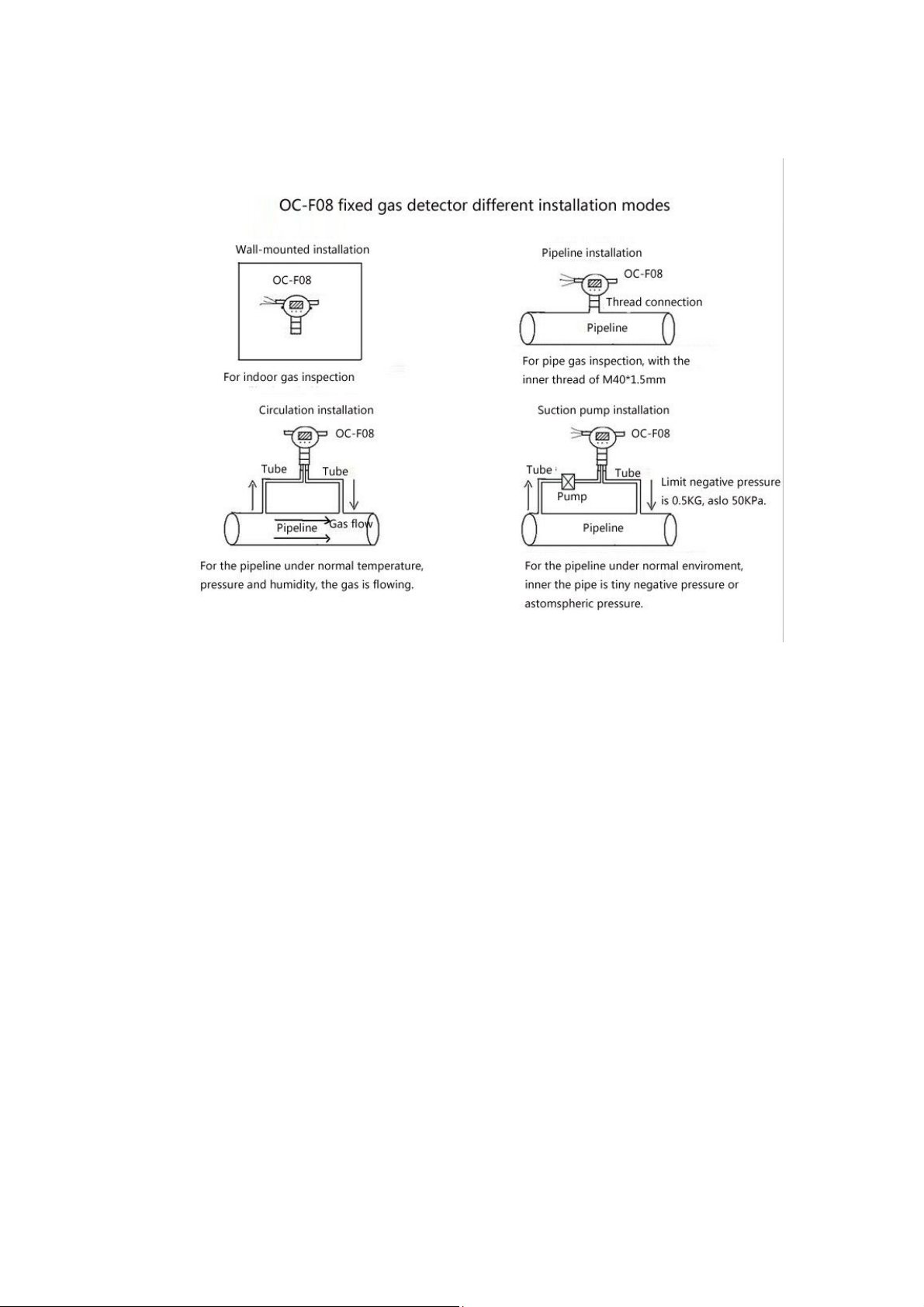
2.2、Different installation mode:
2.3、Connection description
All wire should be in line with the relevant national standards and
industry standards. The DC signal and AC power supply line should not
in one shielding cable. Gas detector should be connected with the earth
through pipeline, holder, or the cable. For the RS485 signal output with
two signal lines, please ensure A and B both use a single shielded
twisted pair line for good signal.
Wiring method:
7
Page 9

Anti-clockwise rotate the upper cap and open it.
Pull out the top level circuit module, it connected with the bottom
module by 10pin wire.
When display the bottom control board, according to the picture C to
connect the wire.
Put the power line and signal line insert into the shell from the
bottom cap left hole.
If need, after insert into the accordingly terminal and then fixed the
power line and signal line.
Remark:
In the explosive dangerous place, the user must cooperate with the
national requirements cable to introduce the device.
In order to assure the gas detector safety, please ensure the detector shell
connected with the earth reliably.
三、Function introduction:
3.1、Normal working mode
Picture 3.1、Opening Display screen
8
Page 10

After power on, firstly display the each parameter, then begin to the
self-test program as the following steps:
1. LCD display all fields, the white backlight is lit;
2. LCD display full range value, the white backlight is lit;
3. LCD display low alarm value, the orange backlight is lit;;
4. LCD display high alarm value, the red backlight is lit;;
5. Enter into pre-heat interface;
6. After preheat, enter into the normal inspection mode.
Picture 3.2、Normal inspection interface
In the process of inspection, when the gas concentration exceed
the set level, AL1 and AL2 will display, meanwhile the red backlight
will light, means it alarm. When the gas detector occur obstacle will
display ERR.01, the orange backlight will light, then please check
and repair timely.
Remark:
Before the inspection interface, if you want to skip the preheat,
then press “ok”. But our engineer suggest not do this, if skip the preheat
time will cause the unstable data.
3.2、Setting interface
Setting interface with the following item: Grade-I (AL1) alarm
9
Page 11

setting --Grade II (AL2) alarm setting—Device address setting—Restore
factory setting—Zero Calibration setting—Gas concentration
setting—Span calibration setting.
Long press the “M” will enter into the Setting interface, then press
the up or down key to adjust the interface; if set the data or function,
press “M”, set the flashing parameter, after the set press “OK” to save
the change, if want to cancel, press the “M” again; long press the “M”,
will back to the normal inspection interface.
3.2.1、AL1 setting:
When the gas concentration data exceed the set level, the red
backlight will be lit, meanwhile the K1 relay will act.
Press “M”, the AL1 flashing, the set digit also flashing, press the ▲
could change the position. Press ▼ could adjust the data, from 0~9,
press “OK” will save the setting. If cancel, press the “M”.
Picture 3.3、AL1 setting interface
3.2.2、AL2 setting:
When the gas concentration data exceed the set level, the red
backlight will be lit, meanwhile the K2 relay will act.
Press “M”, the AL2 flashing, the set digit also flashing, press the ▲
10
Page 12

could change the position. Press ▼ could adjust the data, from 0~9,
press “OK” will save the setting. If cancel, press the “M”.
Picture 3.4、AL2 setting interface
3.2.3、Device address setting:
Picture 3.5、setting the device address interface
Users can set the device address through this interface, the range of the
address is 1---247. Among the RS485 bus system, every device is only.
The function is only useful to this type device which has the RS485
function output.
3.2.4、Restore factory setting:
Picture 3.6、Loading the factory setting interface
11
Page 13

If you want to recover the setting parameters as before, press the M
button, then begin to flash, if need to cancel this, you can press M button,
if you want to confirm the recovering factory settings, you can press the
OK button, and if the recovering setting is ok, then it will turn back the
standard interface automatically, if not, it will stay the primary interface.
3.2.5、Zero calibration setting:
Enter into the Zero Calibration interface, you can press the M
button under this interface.
Picture 3.7、Zero calibration interface
The SET ZERO character flickers and the interface display the
relevant number at the same time, after the number is stable, you can
press the OK button, then the zero demarcated can be finished.
3.2.6、Calibrate gas concentration setting:
After entering the setting interface, you can press the ▼ to change
this interface. If you press M button, the character SET CAL and the
relevant setting digits will flicker, meanwhile, you can input the
calibrated gas concentration. The ▲ has the function of removing the
setting digits, press the ▲ to change the digits you want to set, and press
12
Page 14

the ▼ can change the number of the relevant digits. The number can be
cyclic changed from 0~9, after this, you can press the OK button to
finish the demarcated gas concentration setting, the interface of the
standard gas concentration as below:
Picture 3.8、Calibration gas concentration interface
3.2.7、Span calibrations setting:
It refers to that the users can adjust the instrument by using the
calibration gas. After entering this interface, press the M button to
calibrate, then the SET PEAK becomes flickering. After that, pass
through the standard gas(control the flow as 200ml/min), when the data
stable, press the “OK” to save the setting.
Picture 3.9、Span calibration setting
四、Calibration methods
Before the gas detector leave our factory, we have calibrated it. If
the users have the calibration device, they can calibrate it regularly as the
13
Page 15

instruction. If they don’t have the equipment, they can go to the relevant
measure departments for help or send it to our company, then we can
calibrate it with costs.
In order to assure device measure accuracy, the normal calibrated
cycle of the instrument is 3---6 months. If the inspection place long term
with the higher concentration gas, then the calibrated cycle will be
shortened. So in order to ensure the instrument’s measure accuracy,
should timely calibrate it and save the calibration record.
4.1、Zero calibration
Pass the 0ppm concentration standard gas through the gas detector,
usually as the normal air as the zero, some gas(such as the O2, CO2),
take the N2 as the Zero; then enter into the Zero Calibration interface,
press the “M”, then the SET ZERO flashing, then display the data, when
the data stable, press the “ok” to save the setting and finish the Zero
Calibration.
Remark: Zero calibration must be operated in clean air, do not
operate in the normal working environment.
4.2、Span calibration
Firstly, make the standard gas with set concentration through the
flow meter, and control the flow between 160---300ml/min, then link the
conduit into the instrument tube, then choose the menu and enter the
14
Page 16
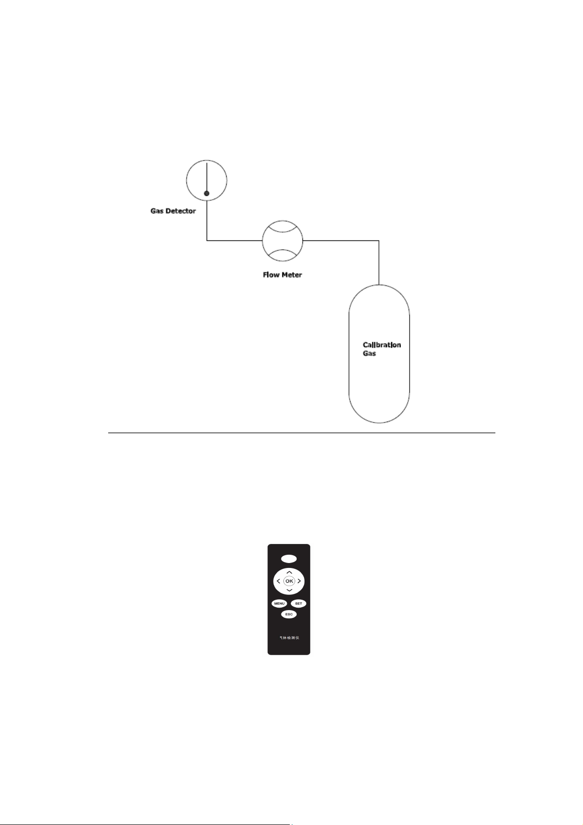
span calibration interface. Press the “M”, the SET PEAK flashing, after
the value is stable(don’t rise or descend any more), press the OK button
to save and exit.
五、Remote controller
Remote controller mainly for the working place with heavy dust or
other place inconvenient for open the cap. This could avoid the danger.
15
Page 17

Enter the “Menu” enter into the setting interface, then use the “<”
“>”to adjust the parameter interface, press the “Set” to adjust the
parameter. Press the “∧”“∨”to adjust the data, press “ok” to save the
setting, if only press “Menu” will not save, press “ESC” will be back to
normal working mode.
六、Notice and maintenance for sensor
Keep the gas detector away from corrosive gas, lampblack, dust and rain
when it working. Avoid the dropping from height or severe vibrations.
Do not regular contact the device with high concentration gas which has
higher concentration than the detecting range, or the sensor life will
reduce.
For mixed combustible gas or liquid vapor, there may be errors in the
detect results, due to the operating environment is different from the
calibration environment.
Recommend sensor life: Catalytic combustion sensor of 3 years,
Electrochemical sensor of 2 years. PID sensor of 3~5 years.
七、Warranty
OC-F08 gas detector with the warranty of 12 month(from the day leave
16
Page 18

factory). During this period, we will be responsible for providing the
free maintain to quality problems of breakdown under normal usage.
Our company disclaim all responsibility for the damage caused by
misuse, manmade damage or natural disaster.
If the sensor life is end, please contact us for replacement.
For the failures which can not be solved locally, please return the device
to distributor or manufacturer for maintenance. Our company will send
back to you as soon as possible.
Technical Specification
Applicable Gas Oxygen, Combustible gas, toxic gas, etc
Detecting Range According to the detected gas
Resolution According to the detected gas
Sampling Diffusion or pump-suction, circulation selectable
Accuracy
Repeatability ≤±1%
Zero drift
Sensor Type
Sensor Life
Response Time (T90) ≤20s
Alarming mode Audible-visual alarm(Optional)
Operating Environment
Working Voltage 24V DC(16~30VDC)
Output Signals
≤±3%F.S
≤±1%(F.S/year)
Catalytic combustion , Electrochemical, PID, Infrared
sensor
2~3 years(Catalytic combustion , Electrochemical)
3~5 years(PID, Infrared)
Temperature: -30℃~60℃ (Customized for special
demands)
Humidity: ≤95%RH (non-condensing); if >90%RH, should
add the filter
Pressure: 86kPa~106kPa
(Standard)Three-wire system 4~20mA standard signals
output, available for PLC, DCS, etc;
(Optional) Four-wire system RS485 digital signal output;
17
Page 19
(Optional) Frequency signal 200~1000Hz output;
Two-level passive contact output:220VAC 0.5A, 5VDC
0.5A
Installation Means Wall mounted, Pipe type (Thread:M40*1.5 )
Material of Body Cast aluminum
Explosion-proof Index Ex d IIC T6
Protection Grade IP66
Electrical Interface 3/4″NPT(Female Screw)、1/2″NPT(Female Screw)
Transmit Distance ≤2000m
Dimension 210 mm×140 mm×92 mm(L×W×H)
Weight About 1.5Kg
Standards GB15322.1-2003 , GB3836.1-2010 , GB3836.2-2010 ,
GB3836.4-2010
Detecting gas list:
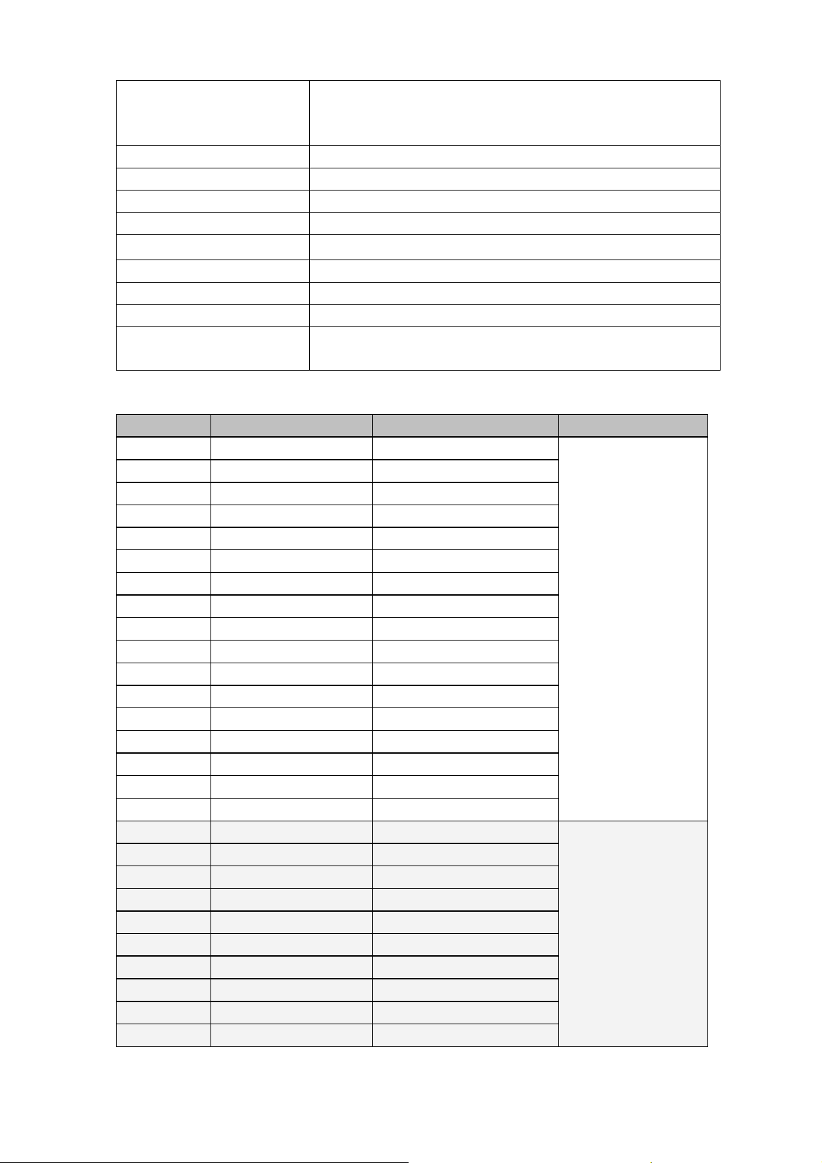
Gas Detecting Range Alarm Threshold Sensor Type
NH3 0-100 PPM 25 PPM / 50 PPM
Cl2 0-50.0 PPM 10 PPM / 20 PPM
H2 0-1000 PPM 50 PPM / 100 PPM
CH2O 0-100 PPM 25 PPM / 50 PPM
O2 0-30.0%vol 18.5%vol / 23.5%vol
H2S 0-100 PPM 10 PPM / 20 PPM
HCl 0-30.0 PPM 5.0 PPM / 10.0 PPM
HCN 0-50.0 PPM 5.0 PPM / 10.0 PPM
PH3 0-20.0 PPM 0.3 PPM / 0.6 PPM
Electrochemical
sensor
HF 0-10.0 PPM 3.0 PPM / 6.0 PPM
NO 0-250 PPM 25 PPM / 50 PPM
CO 0-500 PPM 35 PPM / 70 PPM
SO2 0-20.0 PPM 2.0 PPM / 10.0 PPM
ClO2 0-50.0 PPM 0.3 PPM / 0.5 PPM
NO2 0-20.0 PPM 1.0 PPM / 2.0 PPM
C2H4O 0-100 PPM 10 PPM / 20 PPM
O3 0-20.0 PPM 5.0 PPM / 10.0 PPM
CH4 0-100%LEL 25%LEL / 50%LEL
C3H8 0-100%LEL 25%LEL / 50%LEL
H2 0-100%LEL 25%LEL / 50%LEL
NH3 0-100%LEL 25%LEL / 50%LEL
C2H4O 0-100%LEL 25%LEL / 50%LEL
CH3CH3 0-100%LEL 25%LEL / 50%LEL
Catalytic
combustion sensor
C2H4 0-100%LEL 25%LEL / 50%LEL
C4H10 0-100%LEL 25%LEL / 50%LEL
C4H8 0-100%LEL 25%LEL / 50%LEL
C7H8 0-100%LEL 25%LEL / 50%LEL
18
Page 20

C8H10 0-100%LEL 25%LEL / 50%LEL
CH4O 0-100%LEL 25%LEL / 50%LEL
C2H6O 0-100%LEL 25%LEL / 50%LEL
C3H4O 0-100%LEL 25%LEL / 50%LEL
C2H3Cl 0-100%LEL 25%LEL / 50%LEL
C3H9N 0-100%LEL 25%LEL / 50%LEL
CH3Br 0-100%LEL 25%LEL / 50%LEL
CO2
CH4
Remark: if not listed gas type or measuring range, please contact our company.
0-5.0%vol 1.0%vol / 3.0%vol
0-5000ppm 800 PPM / 1500 PPM
0-5.0%vol
0-100%vol
1.0%vol / 3.0%vol
5%vol / 10%vol
NDIR infrared
sensor
Henan Oceanus
Address: Jinjiang International Garden No.10th, Weilai
Road, Zhengzhou, China
Telephone: +86-371-60998169
Email: [email protected]
Web: http://china-oceanus.com/
19
 Loading...