

Page 1
Vector V320 GNSS Smart Antenna
Part No. 875-0351-0 Rev. A1
User Guide
Page 2

This device complies with part 15 of the FCC Rules. Operation is subject to the following two
conditions:
(1) This device may not cause harmful interference, and
(2) this device must accept any interference received, including interference that may cause
undesired operation.
Copyright Notice
Hemisphere GNSS Precision GNSS Applications
Copyright © Hemisphere GNSS (2015). All rights reserved.
No part of this manual may be reproduced, transmitted, transcribed, stored in a retrieval system or
translated into any language or computer language, in any form or by any means, electronic,
mechanical, magnetic, optical, chemical, manual or otherwise, without the prior written
permission of Hemisphere GNSS.
Trademarks
Hemisphere GNSS®, the Hemisphere GNSS logo, A21TM, A31TM, A42TM, A52TM, AthenaTM, AtlasTM,
EclipseTM, Eclipse VectorTM, e-Dif®, H102TM, H321TM, LX-3TM, PocketMax3TM, R330TM, S320TM,
SBX-4TM, V103TM, V113TM, V320TM, VS330TM, VectorTM are proprietary trademarks of Hemisphere
GNSS. Other trademarks are the properties of their respective owners.
Patents
Hemisphere GNSS products may be covered by one or more of the following U.S. Patents:
6,111,549 6,397,147 6,469,663 6,501,346 6,539,303
6,549,091 6,631,916 6,711,501 6,744,404 6,865,465
6,876,920 7,142,956 7,162,348 7,277,792 7,292,185
7,292,186 7,373,231 7,400,956 7,400,294 7,388,539
7,429,952 7,437,230 7,460,942
Other U.S. and foreign patents pending.
Notice to Customers
Contact your local dealer for technical assistance. To find the authorized dealer near you:
Hemisphere GNSS
8515 East Anderson Drive, Suite A
Scottsdale, Arizona, USA 85255
Phone: 480-348-6380
Fax: 480-270-5070
ww.hgnss.com
w
Technical Support
If you need to contact Hemisphere GNSS Technical Support:
8515 East Anderson Drive, Suite A
Scottsdale, AZ 85255 USA
Phone: 480-348-6380
Fax: 480-270-5070
Documentation Feedback
Hemisphere GNSS is committed to the quality and continuous improvement of our products and
services. We urge you to provide Hemisphere GNSS with any feedback regarding this guide by
writing to the following email address: [email protected].
Page 3

Contents
Contents
Chapter 1 Introduction . . . . . . . . . . . . . . . . . . . . . . . . . . . . . . 1
Overview . . . . . . . . . . . . . . . . . . . . . . . . . . . . . . . . . . . . . . . . . . . . . . . 2
Parts List . . . . . . . . . . . . . . . . . . . . . . . . . . . . . . . . . . . . . . . . . . . . . . . 4
Chapter 2 Installation . . . . . . . . . . . . . . . . . . . . . . . . . . . . . . . 5
Mounting Location . . . . . . . . . . . . . . . . . . . . . . . . . . . . . . . . . . . . . . . 6
GNSS Satellite Reception . . . . . . . . . . . . . . . . . . . . . . . . . . . . . 6
Environmental Considerations . . . . . . . . . . . . . . . . . . . . . . . . . 6
VHF Interference . . . . . . . . . . . . . . . . . . . . . . . . . . . . . . . . . . . . 6
Mounting Orientation . . . . . . . . . . . . . . . . . . . . . . . . . . . . . . . . . . . . 8
V320 Alignment . . . . . . . . . . . . . . . . . . . . . . . . . . . . . . . . . . . . 10
Mounting Options . . . . . . . . . . . . . . . . . . . . . . . . . . . . . . . . . . . . . . 11
V320 Dimensions . . . . . . . . . . . . . . . . . . . . . . . . . . . . . . . . . . . 11
Power/Data Cable Considerations . . . . . . . . . . . . . . . . . . . . . 12
Mounting the V320 . . . . . . . . . . . . . . . . . . . . . . . . . . . . . . . . . 13
Connecting the Serial Cable or Serial-to-NMEA 2000 Adapter
to the V320 . . . . . . . . . . . . . . . . . . . . . . . . . . . . . . . . . . . . . . . . 16
Ports . . . . . . . . . . . . . . . . . . . . . . . . . . . . . . . . . . . . . . . . . . . . . . . . . 18
Serial Ports . . . . . . . . . . . . . . . . . . . . . . . . . . . . . . . . . . . . . . . . 18
NMEA 2000 Port . . . . . . . . . . . . . . . . . . . . . . . . . . . . . . . . . . . . 19
Powering the V320 . . . . . . . . . . . . . . . . . . . . . . . . . . . . . . . . . . . . . . 23
Power Considerations . . . . . . . . . . . . . . . . . . . . . . . . . . . . . . . 23
Connecting to a Power Source . . . . . . . . . . . . . . . . . . . . . . . . 23
Electrical Isolation . . . . . . . . . . . . . . . . . . . . . . . . . . . . . . . . . . 23
Connecting the V320 to External Devices . . . . . . . . . . . . . . . . . . . 24
Power/Data Cable Considerations . . . . . . . . . . . . . . . . . . . . . 24
Power/Data Cable Pin out Specifications . . . . . . . . . . . . . . . . 25
Default Parameters . . . . . . . . . . . . . . . . . . . . . . . . . . . . . . . . . . . . . 26
Chapter 3 Understanding the V320 . . . . . . . . . . . . . . . . . . . 27
GNSS Overview . . . . . . . . . . . . . . . . . . . . . . . . . . . . . . . . . . . . . . . . 28
GNSS Operation . . . . . . . . . . . . . . . . . . . . . . . . . . . . . . . . . . . 28
Differential Operation . . . . . . . . . . . . . . . . . . . . . . . . . . . . . . . 28
V320 Overview . . . . . . . . . . . . . . . . . . . . . . . . . . . . . . . . . . . . . . . . . 30
Fixed Baseline Moving Base Station RTK . . . . . . . . . . . . . . . 30
GLONASS & BeiDou . . . . . . . . . . . . . . . . . . . . . . . . . . . . . . . . 31
L2 Advantage . . . . . . . . . . . . . . . . . . . . . . . . . . . . . . . . . . . . . . 31
Supplemental Sensors . . . . . . . . . . . . . . . . . . . . . . . . . . . . . . . 31
Time Constants . . . . . . . . . . . . . . . . . . . . . . . . . . . . . . . . . . . . 32
V320 GNSS Smart Antenna User Guide iii PN 875-0351-0 Rev A1
Page 4

Contents
Appendix A Troubleshooting . . . . . . . . . . . . . . . . . . . . . . . . . . 34
Appendix B Technical Specifications . . . . . . . . . . . . . . . . . . . 37
Index . . . . . . . . . . . . . . . . . . . . . . . . . . . . . . . . . . . . . . . . . . . . . . . 41
End User License Agreement . . . . . . . . . . . . . . . . . . . . . . . . . . . . 43
Warranty Notice . . . . . . . . . . . . . . . . . . . . . . . . . . . . . . . . . . . . . . 46
V320 GNSS Smart Antenna User Guide iv PN 875-0351-0 Rev A1
Page 5

Chapter 1: Introduction
Chapter 1: Introduction
Overview
Parts List
V320 GNSS Smart Antenna User Guide 1 PN 875-0351-0 Rev A1
Page 6
Chapter 1: Introduction
Overview
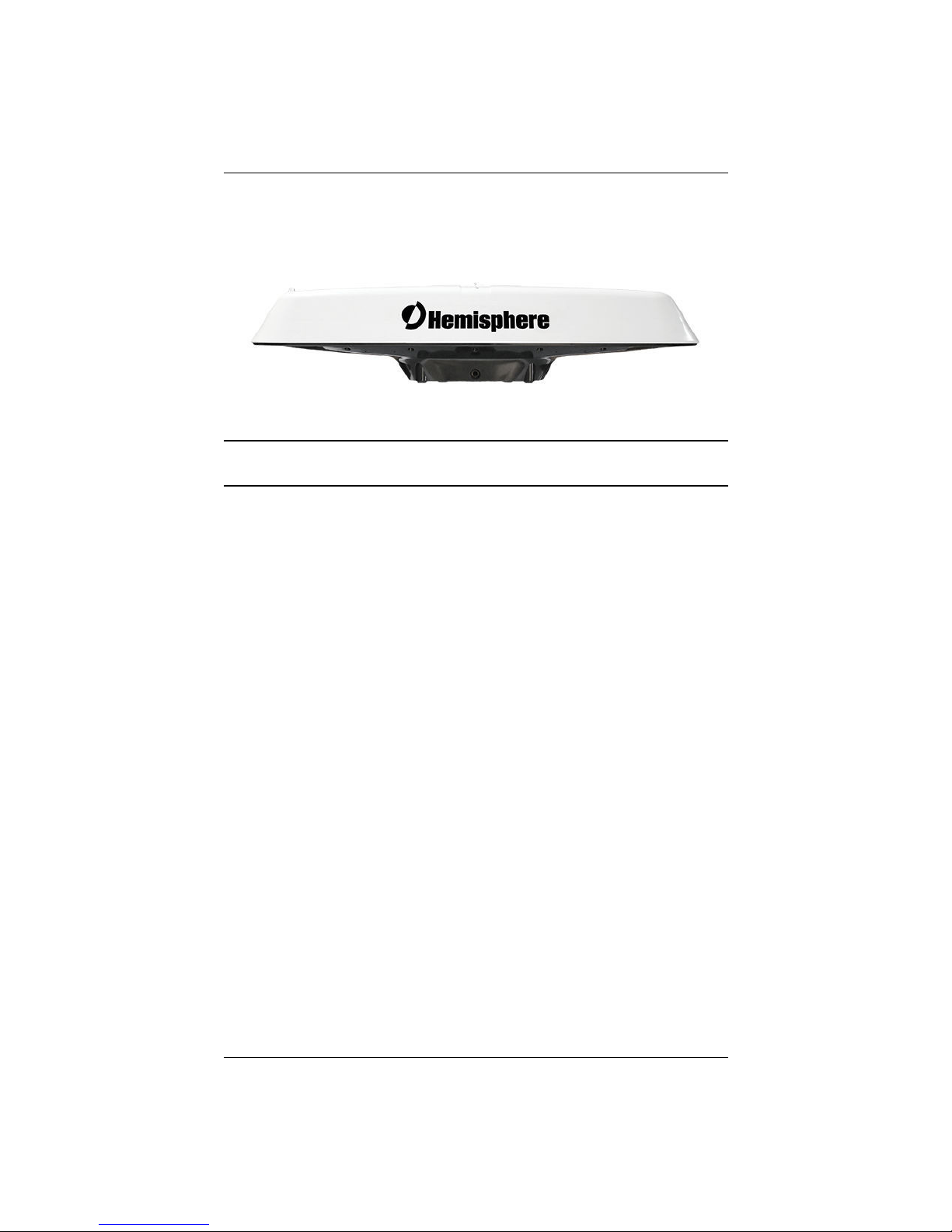
The Eclipse Vector™ V320™ GNSS Smart Antenna supports GNSS, GLONASS,
BeiDou, Athena RTK and Atlas L-band which is based on Hemisphere GNSS’ exclusive
Eclipse Vector™ H321™ GNSS module.
Figure 1-1: V320 side view
Note: When referring to the Vector V320 GNSS Smart Antenna this manual uses the
term V320.
Based on Eclipse Vector™ GNSS technology, the V320 (Figure 1-1) is designed for
marine and land applications that require precise heading and RTK position
performance from the Vector V320 GNSS smart antenna. Featuring an all-in-one
Hemisphere GNSS Eclipse Vector-based receiver and two integrally separated
antennas, with a baseline of 50.0 cm. The V320 achieves heading accuracy of up to
0.17º RMS (depending on environmental conditions) and offers robust positioning
performance.
The standard model V320 tracks L1/L2 GPS, GLONASS and BeiDou. The V320 comes
with Hemisphere’s patented Athena RTK technology and can be upgraded via
subscriptions to support Atlas L-band.
Athena RTK is Hemisphere's most advanced RTK processing software that can be
added to the V320 as a subscription service. Athena RTK has the following benefits:
• Improved Initialization time - Performing initializations in less than 15
seconds at better than 99.9% of the time
• Robustness in difficult operating environments - Extremely high productivity
under the most aggressive of geographic and landscape oriented
environments
Atlas L-band is Hemisphere's industry leading correction service, which can be added
to the V320 as a subscription. Atlas L-band has the following benefits:
• Positioning accuracy - Competitive positioning accuracies down to 2 cm
RMS in certain applications
• Positioning sustainability - Cutting edge position quality maintenance in the
absence of correction signals, using Hemisphere’s patented technology
• Scalable service levels - Capable of providing virtually any accuracy,
precision and repeatability level in the 5 to 100 cm range
• Convergence time - Industry-leading convergence times of 10-40 minutes
V320 GNSS Smart Antenna User Guide 2 PN 875-0351-0 Rev A1
Page 7

Chapter 1: Introduction
For more information about Athena RTK, see: http://hemispheregnss.com/Technology
For more information about Atlas L-band, see: http://hemispheregnss.com/Atlas
Key Features
ey features of the V320 include:
K
• Easy to use all-in-one robust GNSS smart antenna.
• High-precision positioning in Athena RTK, L1/L2, SBAS, beacon, and Atlas Lband
• Athena technology improves RTK performance, especially with GLONASS
and BeiDou
• Atlas* L-band technology provides highly accurate corrections over the air.
*Requires the purchase of a subscription
• Heave of 30 cm RMS (DGNSS), 10 cm (RTK)
• Pitch and roll < 1° RMS
• Accurate heading up to 3 minutes during GNSS outages
• Integrated gyro and tilt sensors deliver fast startup times and provide
heading updates during temporary loss of GNSS
V320 GNSS Smart Antenna User Guide 3 PN 875-0351-0 Rev A1
Page 8
Chapter 1: Introduction
Parts List
Note: The V320’s parts comply with IEC 60945 Section 4.4: “exposed to the weather.”
Table 1-1 lists the parts included with your V320. The V320 GNSS Smart Antenna and
the power/data cable (accessory item) are the only two required components.
able 1-1: Parts list
T
Part Name Qty Part Number
Vector receiver model
(one of the following models)
• V320 1 940-3104-0
All the following are accessory items available for purchase separately from
your V320
Power/data cable, 15m
Power/data cable, 30 m
Each cable includes the following items:
• Clamp
• Screw
• Washer
Serial-to-NMEA 2000 adapter, includes the
following items:
• Screws
• Washers
Installation bracket (black) 1 602-1113-000#
1
1
1 710-0113-000#
880-1042-000
880-1043-000
This User Guide is available for download from the Hemisphere GNSS website at
www.hgnss.com.
V320 GNSS Smart Antenna User Guide 4 PN 875-0351-0 Rev A1
Page 9

Chapter 2: Installation
Chapter 2: Installation
Mounting Location
Mounting Orientation
Mounting Options
Ports
Powering the V320
Connecting the V320 to External Devices
Default Parameters
V320 GNSS Smart Antenna User Guide 5 PN 875-0351-0 Rev A1
Page 10
Chapter 2: Installation
Recessed arrow
Recessed Arrow
Mounting Location
This section provides information on determining the best location for the V320.
GNSS Satellite Reception
When considering where to mount the V320, consider the following satellite reception
recommendations:
• Consider GNSS (and hence SBAS) reception, ensuring there is a clear view
of the sky available to the V320 so the GNSS and SBAS satellites are not
masked by obstructions that may reduce system performance
• Since the V320 computes a position based on the internal primary GNSS
antenna element, mount the V320 where you desire a position with respect
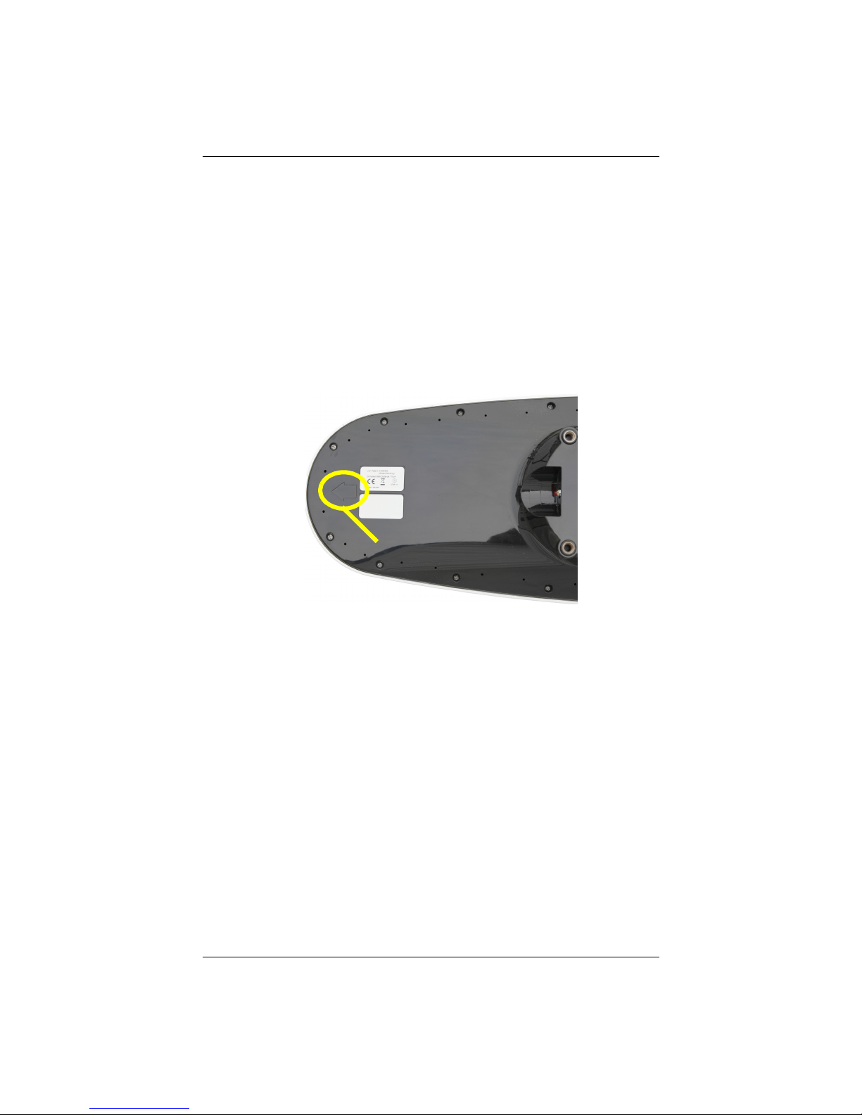
to the primary GNSS antenna (located on the end opposite the recessed
arrow on the underside of the enclosure)
• Locate any transmitting antennas away from the V320 by at least a few
meters to ensure tracking performance is not compromised, giving you the
best performance possible
• Make sure there is enough cable length to route into the vessel to reach a
breakout box or terminal strip
• Do not locate the antenna where environmental conditions exceed those
specified in Table B-5 on page 41
Environmental Considerations
Hemisphere vector smart antennas are designed to withstand harsh environmental
conditions; however, adhere to the following limits when storing and using the V320:
• Operating temperature: -30°C to +70°C (-22°F to +158°F)
• Storage temperature: -40°C to +85°C (-40°F to +185°F)
• Humidity: 95% non-condensing
VHF Interference
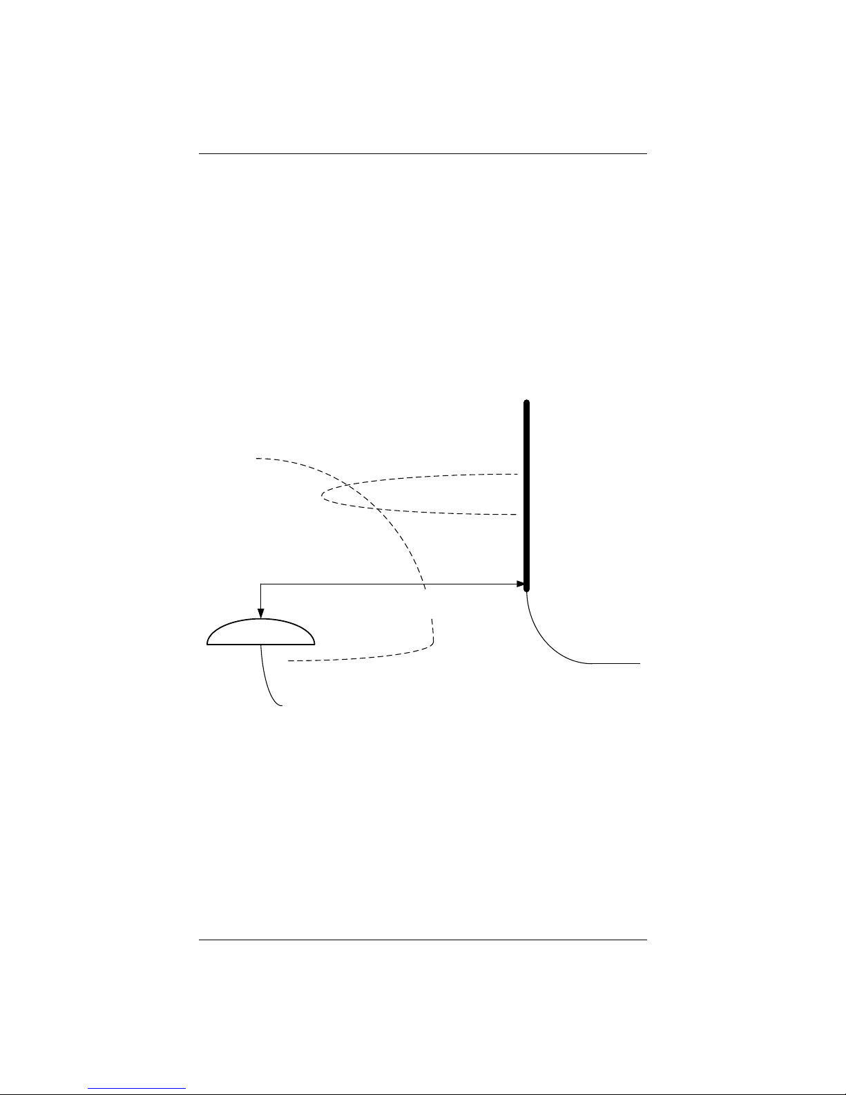
VHF interference from such devices as cellular phones and radio transmitters may
interfere with GPS operation, however the Vector smart antenna can still track
GLONASS and/or BeiDou satellites maintaining heading and position. For example, if
installing the V320 near marine radios consider the following:
V320 GNSS Smart Antenna User Guide 6 PN 875-0351-0 Rev A1
Page 11
Chapter 2: Installation
VHF gain pattern
VHF antenna
GNSS antenna
GNSS gain pattern
Horizontal spacing more than 2 m
Vertical spacing of greater than 2 m
GNSS cable should be 30 cm away from VHF
cable for first 5 m of VHF cable
• VHF marine radio working frequencies (Channels 1 to 28 and 84 to 88) range
from 156.05 to 157.40 MHz. The L1 GNSS working center frequency is
1575.42 MHz. The bandwidth is +/- 2MHz to +/- 10 MHz, which is dependent
on the GNSS antenna and receiver design.
• VHF marine radios emit strong harmonics. The 10th harmonic of VHF radio,
in some channels, falls into the GNSS working frequency band, which may
cause the SNR of GNSS to degrade significantly.
• The radiated harmonic signal strength of different brands/models varies.
• Follow VHF radio manufacturers’ recommendations on how to mount their
radios and what devices to keep a safe distance away.
• Hand-held 5W VHF radios may not provide suitable filtering and may
interfere with the V320’s operation if too close.
Before installing the vector smart antenna use the following diagram to ensure there
are no nearby devices that may cause VHF interference.
Figure 2-1: V320 distance from nearby VHF radios
V320 GNSS Smart Antenna User Guide 7 PN 875-0351-0 Rev A1
Page 12

Chapter 2: Installation
Mounting Orientation
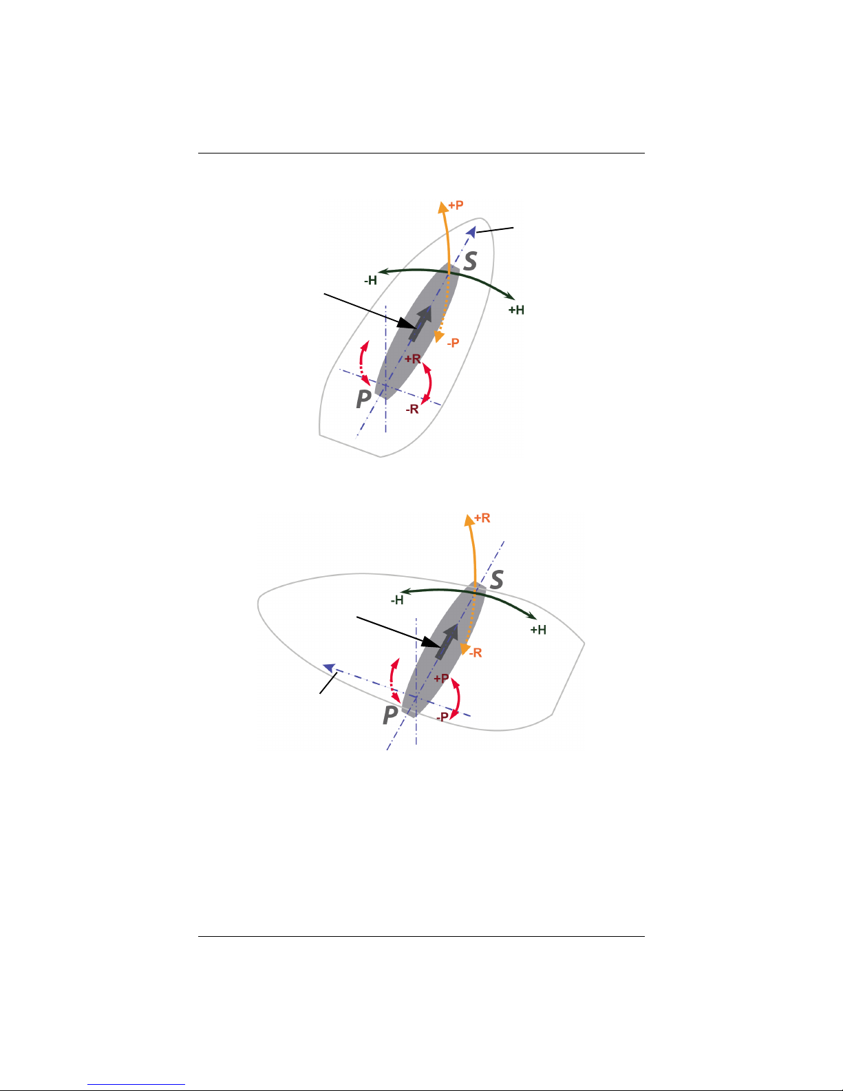
The V320 outputs heading, pitch, and roll readings regardless of the orientation of the
antennas. However, the relation of the antennas to the boat’s axis determines whether
you will need to enter a heading, pitch, or roll bias. The primary antenna is used for
positioning and the primary and secondary antennas, working in conjunction, output
heading, pitch, and roll values.
Note: Regardless of which mounting orientation you use, the V320 provides the
ability to output the heave of the vessel. This output is available via the $GPHEV
message. For more information on this message refer to the Hemisphere GNSS
Technical Reference (go to www.hgnss.com/support and click the GNSS Reference
icon).
Parallel Orientation: The most common installation is to orient the V320 parallel to,
and along the centerline of, the axis of the boat. This provides a true heading. In
this orientation:
• If you use a gyrocompass and there is a need to align the vector smart
antenna, you can enter a heading bias in the V320 to calibrate the physical
heading to the true heading of the vessel.
• You may need to adjust the pitch/roll output to calibrate the measurement if
the Vector is not installed in a horizontal plane.
Perpendicular Orientation: You can also install the antennas so they are oriented
perpendicular to the centerline of the boat’s axis. In this orientation:
• You will need to enter a heading bias of +90° if the primary antenna is on the
starboard side of the boat and -90° if the primary antenna is on the port side
of the boat.
• You will need to configure the receiver to specify the GNSS smart antenna is
measuring the roll axis using $JATT,ROLL,YES.
• You will need to enter a roll bias to properly output the pitch and roll values.
• You may need to adjust the pitch/roll output to calibrate the measurement if
the Vector is not installed in a horizontal plane.
V320 GNSS Smart Antenna User Guide 8 PN 875-0351-0 Rev A1
Page 13
Chapter 2: Installation
Forward
motion
Recessed arrow
located on
bottom of
enclosure
Forward
motion
Recessed arrow
located on
bottom of
enclosure
Figure 2-2 and Figure 2-3 provide mounting orientation examples.
Figure 2-2: Recommended orientation and resulting signs of HPR values
Figure 2-3: Alternate orientation and resulting signs of HPR values
V320 GNSS Smart Antenna User Guide 9 PN 875-0351-0 Rev A1
Page 14
Chapter 2: Installation
V320 Alignment
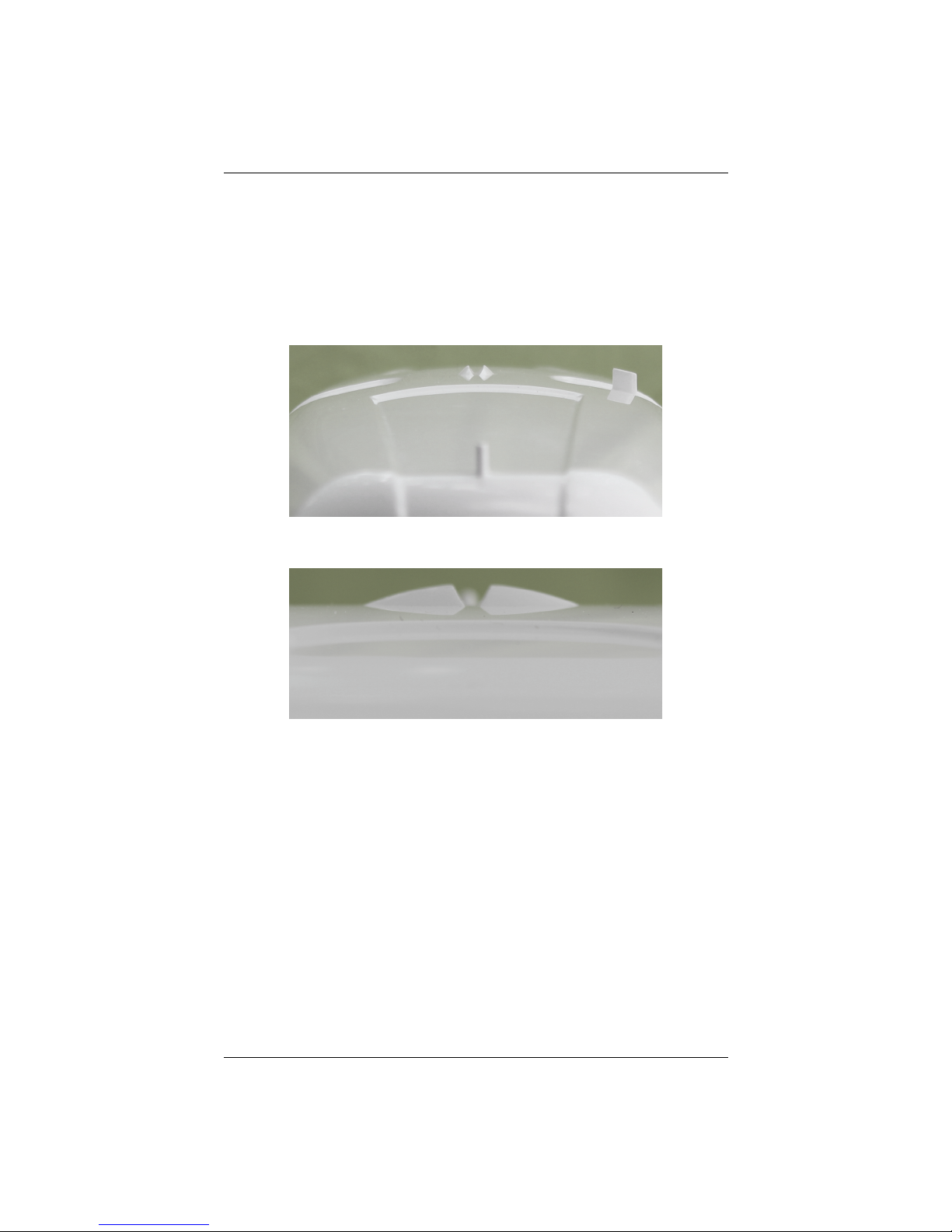
The top of the V320 enclosure incorporates sight design features to help you align the
enclosure with respect to an important feature on your vessel.
To use the sights, center the small post on the opposite side of the enclosure from
you, within the channel made in the medallion located in the center of the enclosure
top as shown in Figure 2-4 and Figure 2-5. Alignment accuracy when looking through
the long site (Figure 2-4) is approximately +/- 1°, while alignment through the short
site (Figure 2-5) is approximately +/- 2.5°.
Figure 2-4: Long site alignment
Figure 2-5: Short sight alignment
If you have another accurate source of heading data on your vessel, such as a
gyrocompass, you may use its data to correct for a bias in V320 alignment within the
V320 software configuration. Alternatively, you can physically adjust the heading of
the V320 so that it renders the correct heading measurement; however, adding a
software offset is an easier process.
V320 GNSS Smart Antenna User Guide 10 PN 875-0351-0 Rev A1
Page 15
Chapter 2: Installation
C
L
C
L
145.94 mm
(5.745 in)
662.29 mm
(26.074 in)
Set screw, 3/8-16 UNC thread size
2 places
208.38 mm
(8.203 in)
46.99 mm
(1.850 in)
93.98 mm
(3.70 in)
76.20 mm
(3.000 in)
152.40 mm
(6.000 in)
M8 x 1.25 thread size
8 places
1-14 UNS thread size
101.60 mm
(4.000 in)
31.75 mm
(1.250 in)
63.50 mm
(2.500 in)
50.80 mm
(2.000 in)
Note: This drawing
shows the Serialto-NMEA 2000
adapter attached
Mounting Options
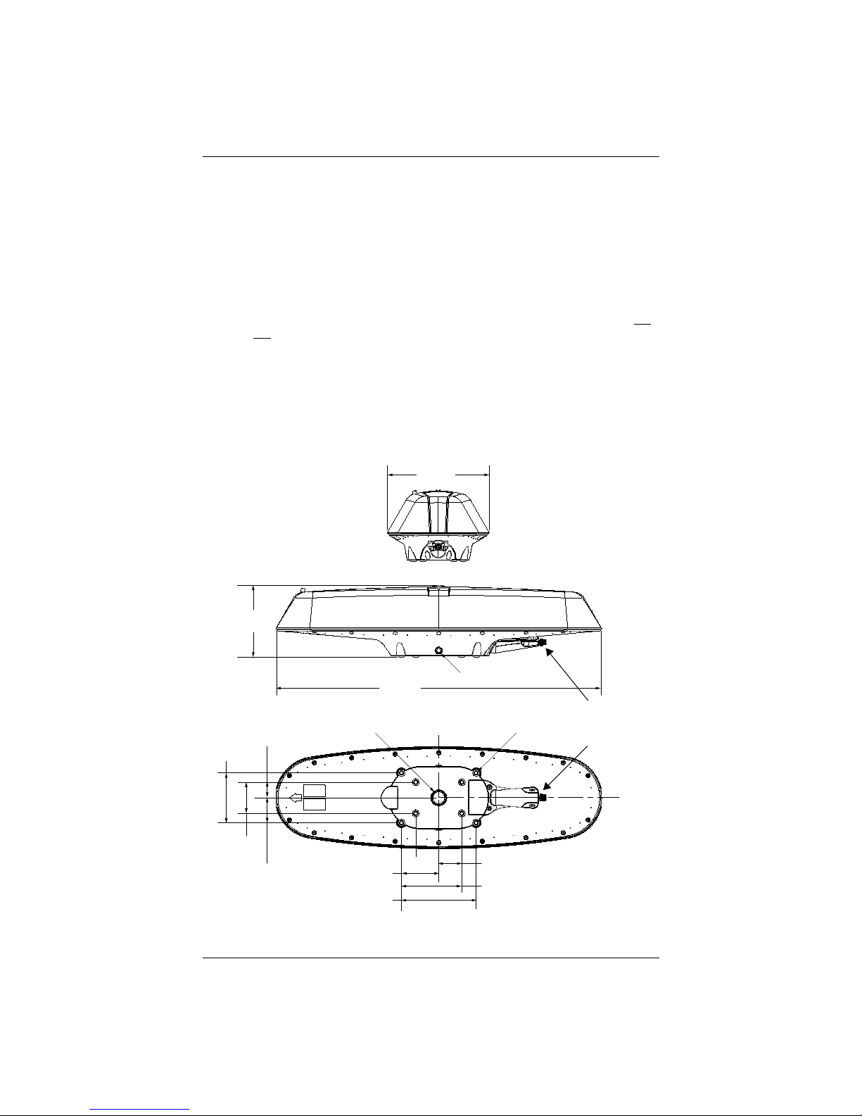
The V320 allows for two different mounting options: flush mount and pole mount.
• Flush mount - The bottom of the V320 contains eight M8-1.25 holes for flush
mounting the unit to a flat surface (see Figure 2-6). The eight holes comprise
two sets of four holes. The inner four holes are in the same location as the
V102, allowing you to use the V320 as a drop-in replacement. The outer four
holes provide a wider mounting option.
• Pole mount - The bottom of the V320 contains a mounting plate with a hole
(1" thread, 0.9" depth) for easy pole mounting. Hand tighten until snug (do
not over-tighten). The set screws on the long sides of the base (see middle
drawing in Figure 2-6) allow you to secure the V320 in place (3/16” Allen
wrench not included).
• Bracket mount - You can purchase on optional mounting bracket. See
Table 1-1 on page 4 for bracket part information.
V320 Dimensions
Figure 2-6 illustrates the physical dimensions of the V320.
V320 GNSS Smart Antenna User Guide 11 PN 875-0351-0 Rev A1
Figure 2-6: V320 dimensions
Page 16
Chapter 2: Installation
Power/Data Cable Considerations
Before mounting the V320 consider the following regarding power/data cable routing:
• Cable must reach an appropriate power source
• Cable may connect to a data storage device, computer, or other device that
accepts GNSS data
• Avoid running the cable in areas of excessive heat
• Keep cable away from corrosive chemicals
• Do not run the cable through door or window jams
• Keep cable away from rotating machinery
• Do not crimp or excessively bend the cable
• Avoid placing tension on the cable
• Remove unwanted slack from the cable at the V320 end
• Secure along the cable route using plastic wraps
Improperly installed cable near machinery can be dangerous.
V320 GNSS Smart Antenna User Guide 12 PN 875-0351-0 Rev A1
Page 17
Chapter 2: Installation
Mounting the V320
This section describes how to flush mount or pole mount the V320.
Keep the following in mind when planning your installation:
• Hemisphere GNSS does not supply mounting surface hardware or a
mounting pole. You must supply the appropriate hardware or mounting pole
required to complete V320 installation.
• You do not necessarily need to orient the antenna precisely as you can enter
a software offset to accommodate for a heading measurement bias due to
installation.
Flush Mounting the V320
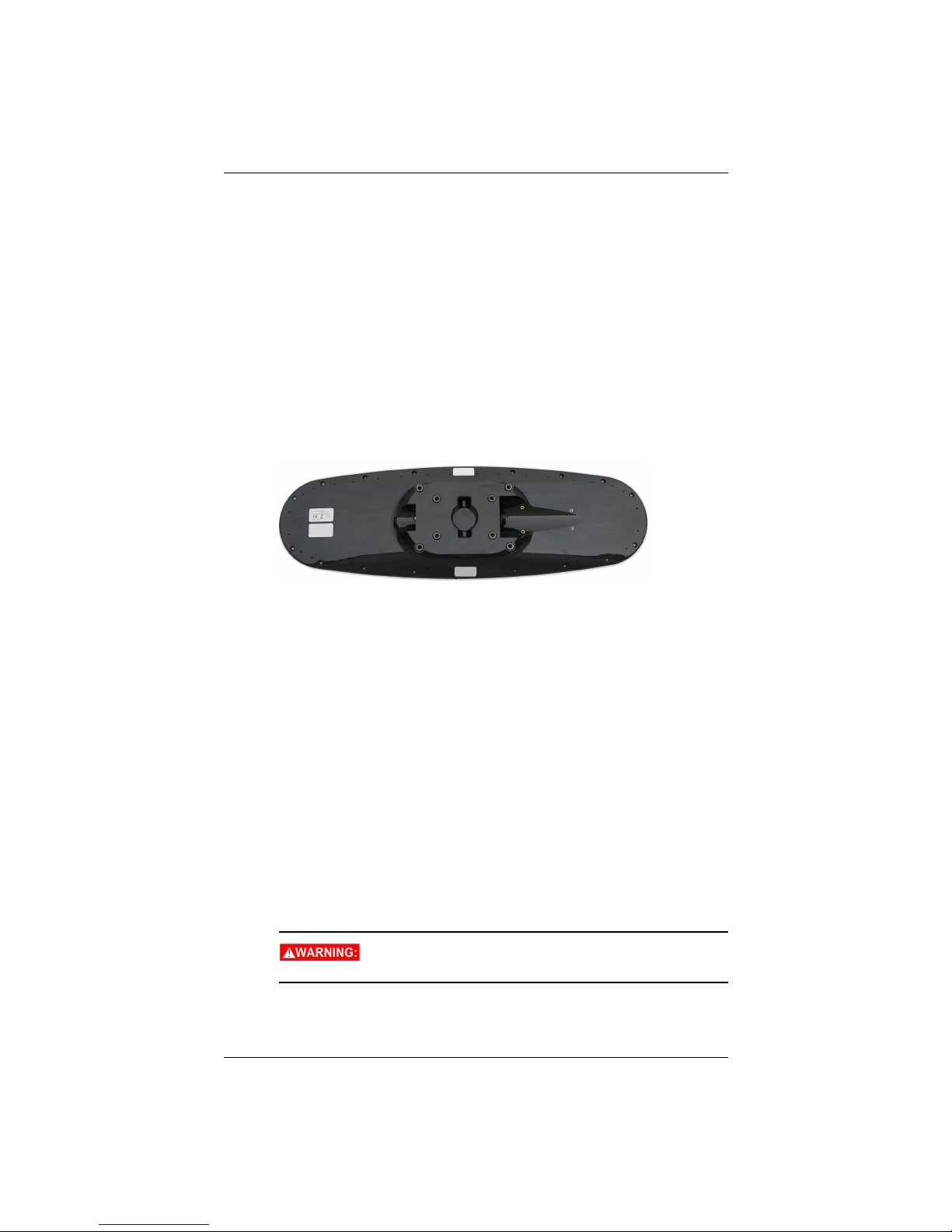
The bottom of the V320 contains eight holes (two sets of four holes) for flush
mounting the unit to a flat surface (Figure 2-7). The flat surface may be something you
fabricate per your installation, an off-the-shelf item (such as a radar mounting plate),
or an existing surface on your vessel.
Figure 2-7: Flush mounting holes on bottom of V320
Complete the following steps to flush mount the V320:
1. Determine the desired location and proper orientation for the V320. See
“Mounting Orientation” on page 8 for information on determining the
desired orientation.
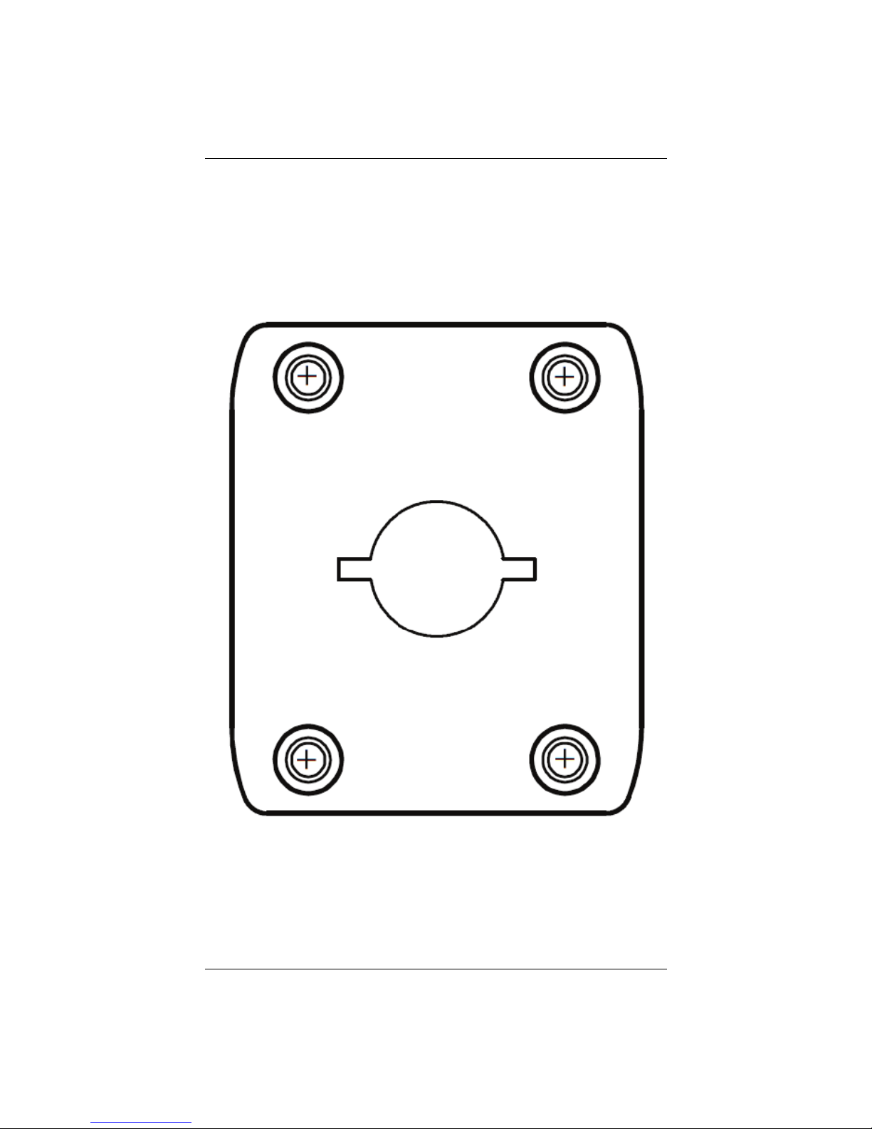
2. Use the supplied template of the V320 that contains the four mounting holes
(see template below) for use as a template to plan the mounting hole
locations.
Always check the printed template against the bottom of the V320 to ensure
you have the right size and the holes lineup.
3. Mark the mounting hole centers on the mounting surface.
4. Place the V320 over the marks to ensure the planned hole centers align with
the true hole centers (adjusting as necessary).
5. Use a center punch to mark the hole centers.
6. Drill the mounting holes with a 9 mm bit appropriate for the surface.
7. Place the V320 over the mounting holes and insert the mounting screws
through the bottom of the mounting surface into the V320.
When installing the V320, hand tighten only. Damage
resulting from over-tightening is not covered by the warranty.
V320 GNSS Smart Antenna User Guide 13 PN 875-0351-0 Rev A1
Page 18
Chapter 2: Installation
Flush Mount Template
Print this page with a 1:1 setting on your printer. This will create a usable template for
mounting the V320 to any mountable surface.
V320 GNSS Smart Antenna User Guide 14 PN 875-0351-0 Rev A1
Page 19
Chapter 2: Installation
Pole Mounting the Vector Smart Antenna
If you need the GNSS-assisted roll measurement, install the V320 perpendicular to the
vessel’s axis. If you do not need this measurement, install the V320 parallel with the
vessel’s axis. For more information refer to Figure 2-2 and Figure 2-3 on page 9.
Complete the following steps to pole mount the V320:
1. Determine the desired location and proper orientation for the V320. See
“Mounting Orientation” on page 8 for information on determining the
desired orientation.
2. Using the provided mounting bracket, secure the bracket to the bottom of
the V320 using the four (4) M8 screws and washers included in the package.
The bracket is secured by placing it against the bottom of the V320 and
adding a washer to the M8 screw to ensure a tight connection.
3. Hand tighten each screw to the bottom of the V320 until snug.
4. Place the V320 on the pole and hand tighten the V320 on the pole until snug
(unit is stable on pole) while ensuring correct orientation.
Hand tighten only. Damage resulting from over-tightening is
not covered by the warranty.
5. Use the full threaded set screws on the long sides of the base (see Figure 2-6
on page 11) to secure the V320 in place (3/16” Allen wrench).
V320 GNSS Smart Antenna User Guide 15 PN 875-0351-0 Rev A1
Page 20
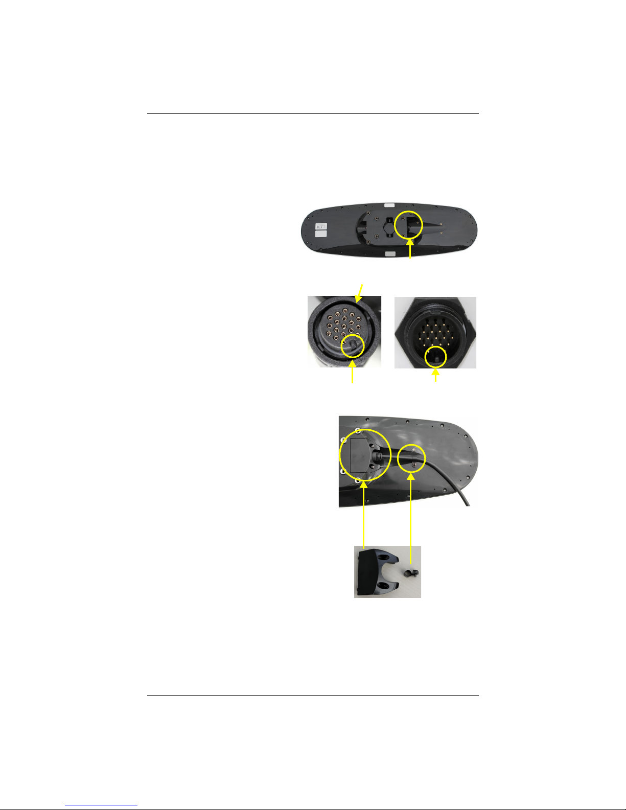
Chapter 2: Installation
Cable connector V320
Connect cable here
key-way connector key
Cable ring
Steps 1&2:
Attach
cable
to unit
Steps 3&4:
Attach clamp and
cable to unit
Step 5:
Attach
cable
cover
Connecting the Serial Cable or Serial-to-NMEA 2000 Adapter
to the V320
After you mount the V320 connect either the serial power/data cable or the
serial-to-NMEA 2000 adapter to the V320.
Connecting the Serial Power/Data Cable
1. Align the cable connector
key-way with the V320
connector key.
2. Rotate the cable ring
clockwise until it locks. The
locking action is firm; you
will feel a positive “click”
when it has locked.
3. Attach the power/data cable to the
cable clamp.
4. Fasten the clamp to the bottom of
the V320 using the screw and
washer.
5. Attach the cable cover.
V320 GNSS Smart Antenna User Guide 16 PN 875-0351-0 Rev A1
Page 21
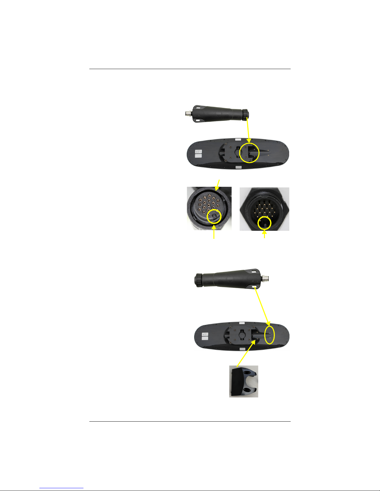
Chapter 2: Installation
Cable connector V320
Connect
key-way connector key
Cable ring
Steps 1&2:
Attach
adapter
to unit
adapter here
Step 3:
Fasten
Step 4: Attach
cable cover
adapter
to unit
Connecting the Serial-to-NMEA 2000 Adapter
For more information on the serial-to-NMEA 2000 adapter see “NMEA 2000 Port” on
page 19.
1. Align the adapter connector
key-way with the V320
connector key.
2. Rotate the cable ring
clockwise until it locks. The
locking action is firm; you
will feel a positive “click”
when it has locked.
3. Fasten the adapter to the body of
the V320 using the provided
screws and the two slots in the
adapter.
4. Attach the cable cover.
V320 GNSS Smart Antenna User Guide 17 PN 875-0351-0 Rev A1
Page 22

Chapter 2: Installation
Ports
The V320 offers either serial port or NMEA 20 00 port functionality.
Serial Ports
The V320 has three ports (Port A, Port B, and Port C), where:
• Port A can be both full-duplex RS-232 and half-duplex RS-422 (transmit only)
• Port B is full-duplex RS-422
• Port C is for NMEA 2000 and only available via serial-to-NMEA 2000 adapter
You can receive external differential corrections via either Port A (full-duplex RS-232)
or Port B (full-duplex RS-422). You can connect up to three devices at one time using
two ports. One device can receive data via Port A (RS-422 transmit only) while two
devices can transmit and receive data via Ports A and B (one connected to Port A RS232 and one connected to Port B).
Note: Port A (RS-422) or Port B is required for communicating to an IMO-approved
device.
You can update firmware via Port A (RS-232) or Port B.
Note: The V320 has maximum baud rate of 38400.
Serial Port Configuration
You may configure Port A or Port B of the GNSS receiver to output any combination of
data. Port A can have a different configuration from Port B in terms of data message
output, data rates, and the baud rate of the port. This allows you to configure the ports
independently based upon your needs.
For example, if you want one generalized port and one heading-only port, you can
configure the ports as follows:
• Port A to have GPGGA, GPVTG, GPGSV, GPZDA, and GPHDT all output at 1
Hz over a 19200 baud rate.
• Port B for GPHDT and GPROT message output at their maximum rate of 20
Hz over a 19200 baud rate.
The messages you configure each port to output and the rate of the port will be the
same for both RS-232 and RS-422 interface levels. For example, the RS-232 Port A and
RS-422 Port A output the same data messages at the same baud rate. If the baud rate
or messages for the RS-422 port need to be changed, this needs to be commanded
through the RS-232 port.
Both RS-232 and RS-422 output signals may be used simultaneously.
Note: For successful communications use the 8-N-1 protocol and set the baud rate of
the V320’s serial ports to match that of the devices to which they are connected. Flow
control is not supported.
V320 GNSS Smart Antenna User Guide 18 PN 875-0351-0 Rev A1
Page 23
Chapter 2: Installation
Selecting Baud Rates and Message Types
When selecting your baud rate and message types use the following formula to
calculate the bits/sec for each message and then sum the results to determine the
baud rate for your required data throughput.
Message output rate * Message length (bytes) * bits in byte = Bits/second
(1 character = 1 byte, 8 bits = 1 byte, use 10 bits/byte to account for overhead)
See “Common Commands and Messages” on page 34 for an example of this
calculation. For information on message output rates refer to the Hemisphere GNSS
Technical Reference (go to www.hgnss.com/support and click the GNSS Reference
con).
i
Recommendations for Connecting to Other Devices
When interfacing to other devices, ensure the transmit data output from the V320 is
connected to the data input of the other device. The signal grounds must also be
connected.
Since RS-422 is a balanced signal with positive and negative signals referenced to
ground, ensure you maintain the correct polarity. For example, when connecting the
transmit data output positive signal to the receive line of the other device, it should be
connected to the receive positive terminal. The negative transmit data signal from the
V320 is then connected to the receive data negative input of the other device.
There is likely little reason to connect the receive data input of the V320 to another
device unless it is able to send configuration commands to the V320. Since the V320
uses proprietary NMEA 0183 commands for control over its configuration, the vast
majority of electronics will not be able to configure its settings unless the other device
has a terminal setting where you can manually issue commands.
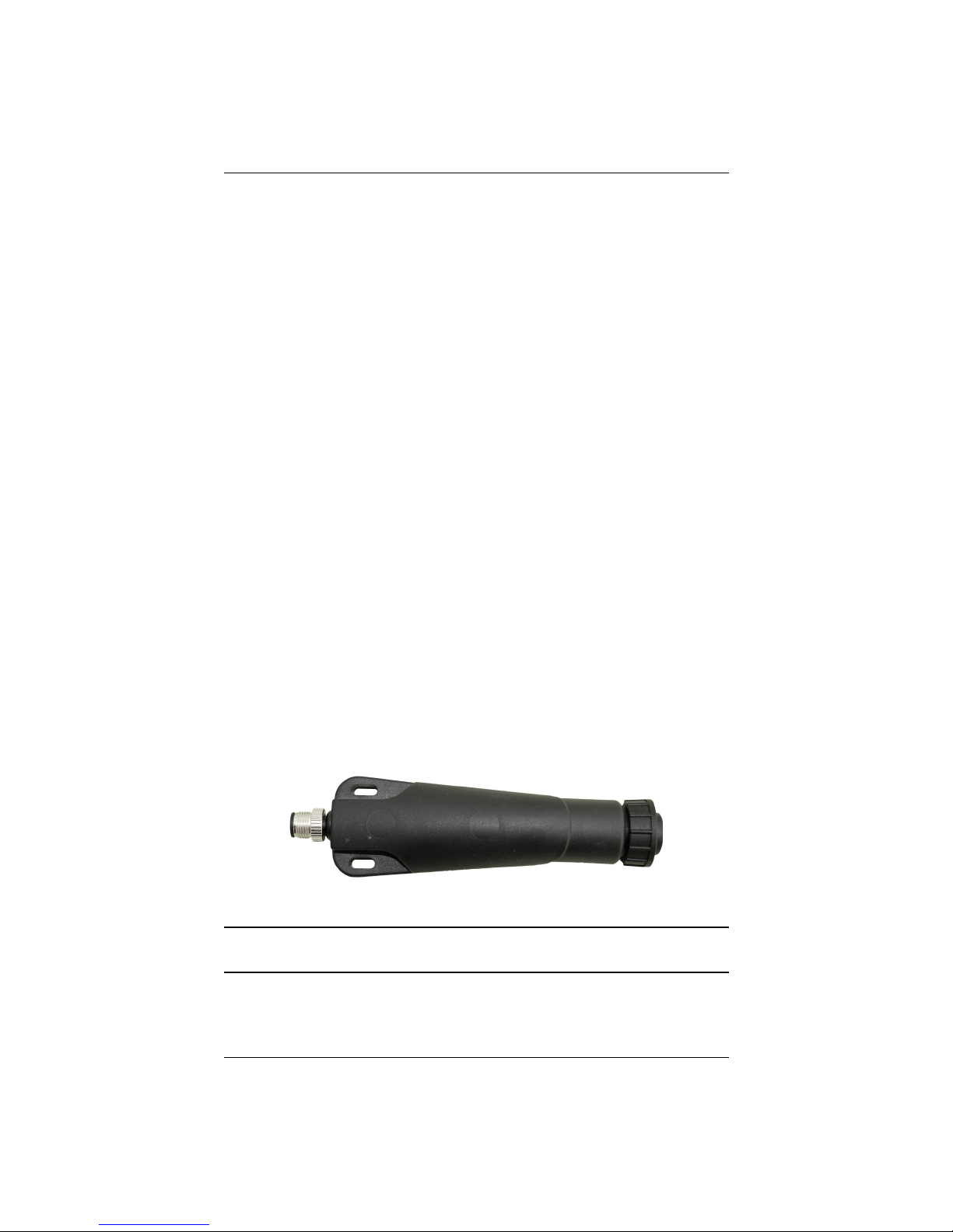
NMEA 2000 Port
To use V320 for NMEA 20 00 you have to connect the included serial-to-NMEA 2000
adapter (P/N 710-0113-0 00#, see Figure 2-8) to the unit. Insert the 18-pin connector of
the adapter into the male end of the 18-pin connector on the V320 by aligning the
keys. You can then attach the adapter to the unit using the supplied screws (machine,
8-32, ½”, PPHC, SS) and washer (flat, #8, SS). The 5-pin male Micro-C connector
connects to your NMEA 200 0 drop cable.
Figure 2-8: Serial-to-NMEA 200 0 adapter
Note: The serial-to-NMEA 200 0 adapter is not an IMO requirement and may not be
used in such an application.
V320 GNSS Smart Antenna User Guide 19 PN 875-0351-0 Rev A1
Page 24
Chapter 2: Installation
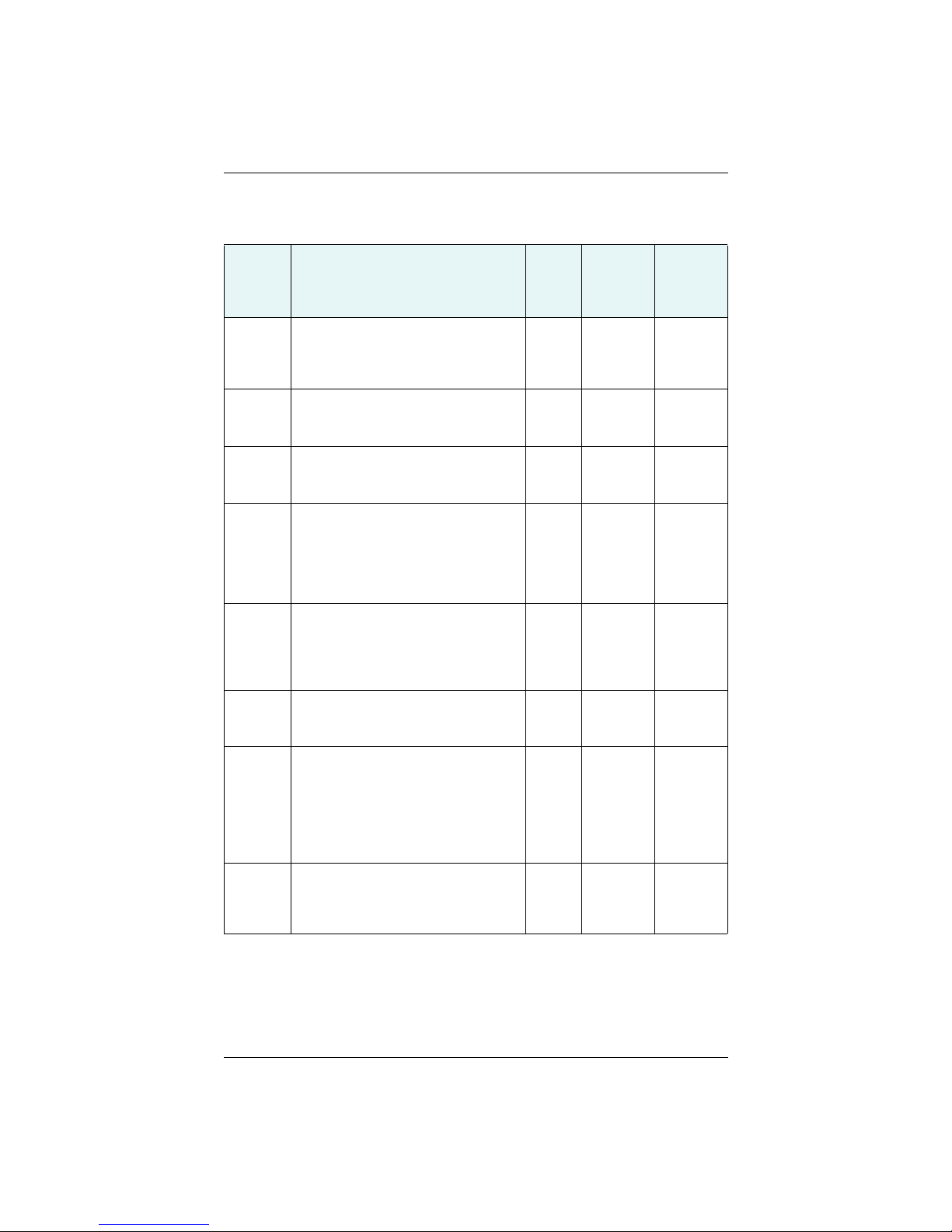
Table 2-1 shows the requested PGNs with the V320 in NMEA 20 00 mode.
Table 2-1: Received messages based on a request
PG No.
(PGN)
059392 ISO Acknowledgement
059904 ISO Request
060928 ISO Address Claim
126996 Product Information
126464 Receive/Transmit PGNs group function
129538 GNSS Control Status
129545 GNSS RAIM Output
129546 GNSS RAIM Settings
Description Level
Used to acknowledge the status of
certain requests addressed to a specific
ECU.
Request the transmission of a specific
PGN, addressed or broadcast.
Used to identify to other ECUs the
address claimed by an ECU.
NMEA 2000 database version supported,
manufacturer’s product code, NMEA
2000 certification level, Load
Equivalency number, and other productspecific information.
The Transmit / Receive PGN List Group
type of function is defined by first field.
The message will be a Transmit or
Receive PGN List group function.
GNSS common satellite receiver
parameter status.
Used to provide the output from a GNSS
receiver's Receiver Autonomous
Integrity Monitoring (RAIM) process. The
Integrity field value is based on the
parameters set in PGN 129546 GNSS
RAIM Settings.
Used to report the control parameters
for a GNSS Receiver Autonomous
Integrity Monitoring (RAIM) process.
Default
Update
Rate
(msec)
B On
Request
B On
Request
B On
Request
B On
Request
B On
Request
B On
Request
B On
Request
B On
Request
Freq (Hz)
On
Request
On
Request
On
Request
On
Request
On
Request
On
Request
On
Request
On
Request
V320 GNSS Smart Antenna User Guide 20 PN 875-0351-0 Rev A1
Page 25
Chapter 2: Installation
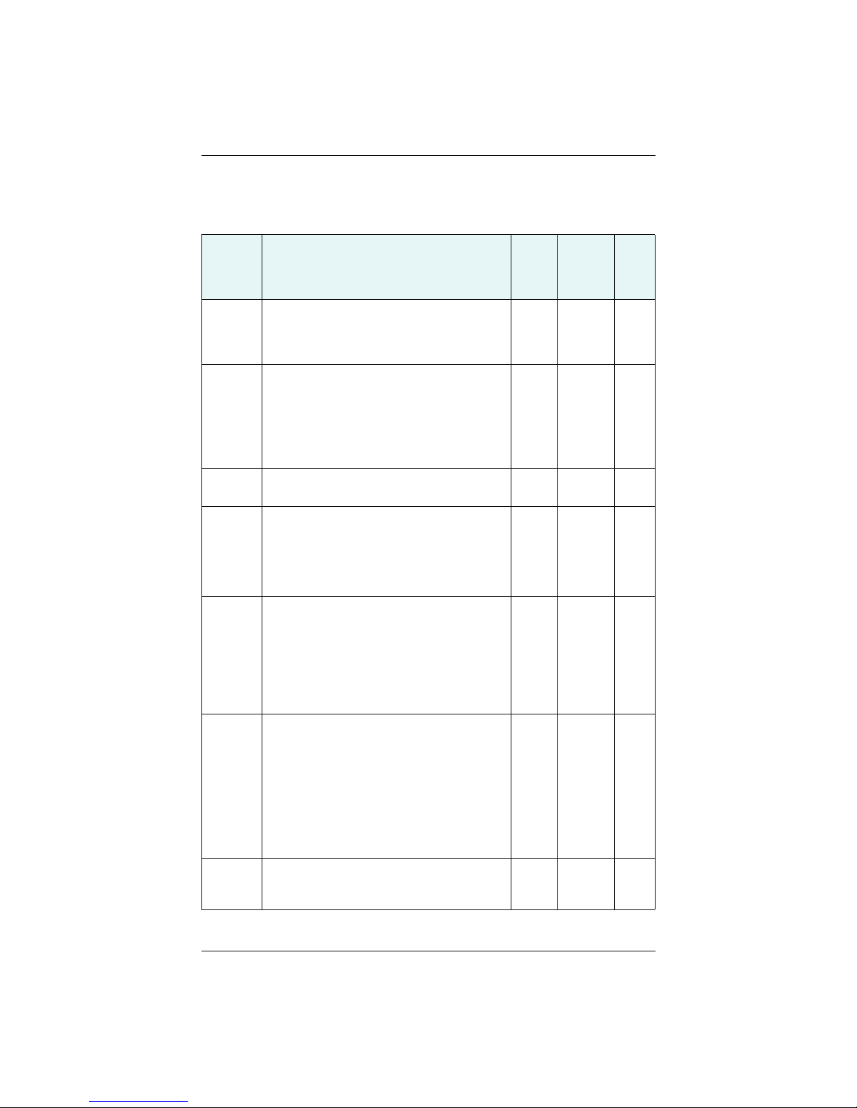
Table 2-2 shows the transmitted PGNs with their default update rate with the V320 in
NMEA 2000 mode.
Table 2-2: Transmitted messages
PG No.
(PGN)
126992 System Time
127250 Vessel Heading
127251 Rate of Turn
127257 Attitude
127258 Magnetic Variation
129025 Position, Rapid Update
129026 COG & SOG, Rapid Update
Description Level
The purpose of this PGN is twofold: To provide a
regular transmission of UTC time and date. To
provide synchronism for measurement data.
Heading sensor value with a flag for True or
Magnetic. If the sensor value is Magnetic, the
deviation field can be used to produce a
Magnetic heading, and the variation field can be
used to correct the Magnetic heading to produce
a True heading.
Rate of change of the Heading.
Provides a single transmission that describes
the position of a vessel relative to both
horizontal and vertical planes. This would
typically be used for vessel stabilization, vessel
control and onboard platform stabilization.
Message for transmitting variation. The
message contains a sequence number to allow
synchronization of other messages such as
Heading or Course over Ground. The quality of
service and age of service are provided to
enable recipients to determine an appropriate
level of service if multiple transmissions exist.
Provides latitude and longitude referenced to
WGS84. Being defined as single frame message,
as opposed to other PGNs that include latitude
and longitude and are defined as fast or multipacket, this PGN lends itself to being transmitted
more frequently without using up excessive
bandwidth on the bus for the benefit of
receiving equipment that may require rapid
position updates.
Single frame PGN that provides Course Over
Ground (COG) and Speed Over Ground (SOG).
Default
Update
Rate
(msec)
B
B 100 10
B 100 10
B 1000 1
B 100 10
B 250 4
1000 1
1000 1
Freq
(Hz)
V320 GNSS Smart Antenna User Guide 21 PN 875-0351-0 Rev A1
Page 26
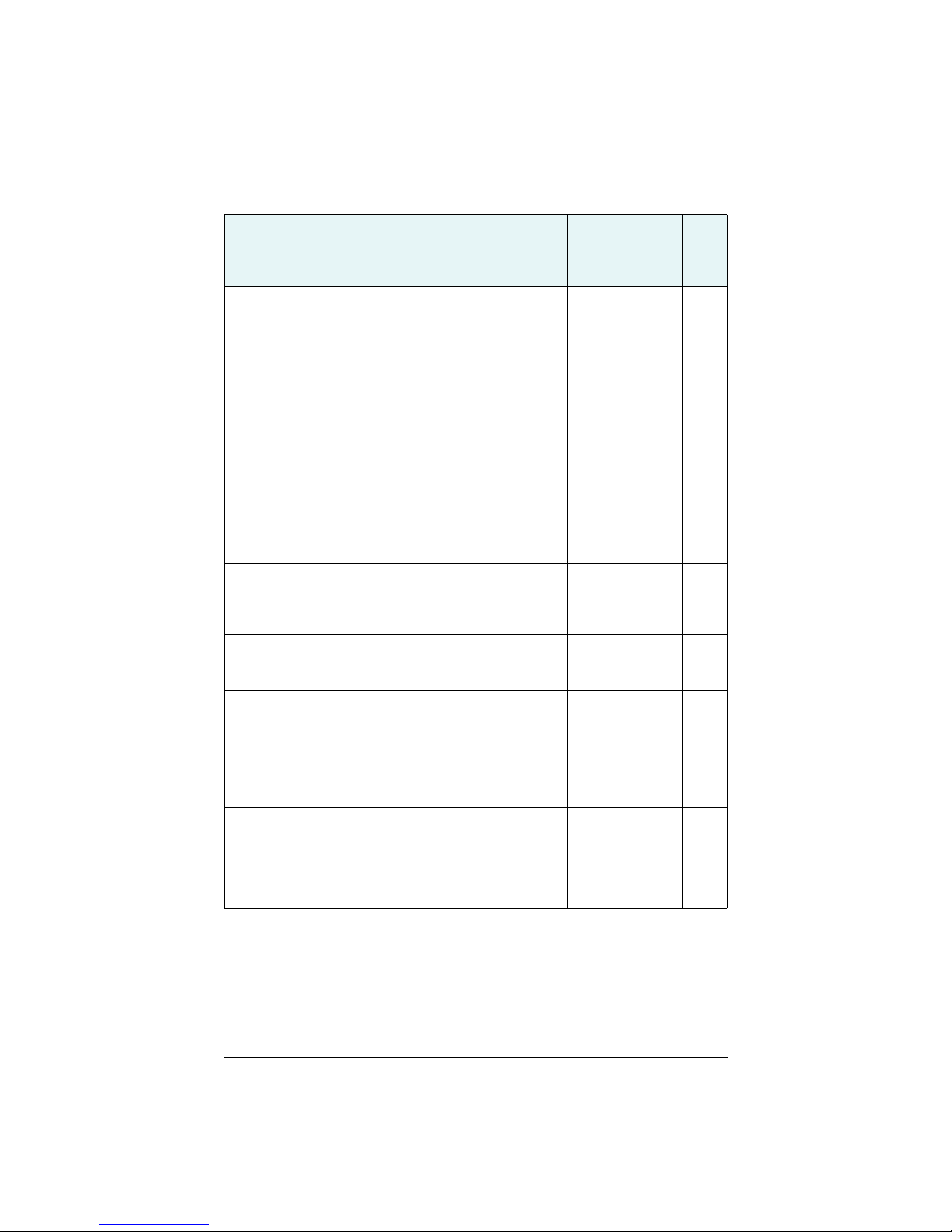
Chapter 2: Installation
Table 2-2: Transmitted messages (continued)
PG No.
(PGN)
Description Level
129027 Position Delta, High Precision Rapid Update
The ‘Position Delta, High Precision Rapid
Update’ Parameter Group is intended for
applications where very high precision and very
fast update rates are needed for position data.
This PGN can provide delta position changes
down to 1 mm with a delta time period accurate
to 5 msec.
129028 Altitude Delta, High Precision Rapid Update
The ‘Altitude Delta, High Precision Rapid Update’
Parameter Group is intended for applications
where very high precision and very fast update
rates are needed for altitude and course over
ground data. This PG can provide delta altitude
changes down to 1 millimeter, a change in
direction as small as 0.0057°, and with a delta
time period accurate to 5 msec.
129029 GNSS Position Data
Conveys a comprehensive set of Global
Navigation Satellite System (GNSS) parameters,
including position information.
129033 Time & Date
Single transmission that provides UTC time,
UTC Date, and Local Offset.
129539 GNSS DOPs
Provides a single transmission containing GNSS
status and dilution of precision components
(DOP) that indicate the contribution of satellite
geometry to the overall positioning error. There
are three DOP parameters reported: horizontal
(HDOP), Vertical (VDOP), and time (TDOP).
129540 GNSS Sats in View
GNSS information on current satellites in view
tagged by sequence ID. Information includes
PRN, elevation, azimuth, SNR, defines the
number of satellites; defines the satellite
number and the information.
Default
Update
Rate
(msec)
B 100 10
B 100 10
B 1000 1
B 1000 1
B 1000 1
B 1000 1
Freq
(Hz)
V320 GNSS Smart Antenna User Guide 22 PN 875-0351-0 Rev A1
Page 27

Chapter 2: Installation
Powering the V320
Power Considerations
For best performance use a clean and continuous power supply. The V320 power
supply features reverse polarity protection but will not operate with reverse polarity.
See Table B-3 on page 41 for complete power specifications.
Connecting to a Power Source
Note: This section refers to powering the unit via serial connection. To power the unit
via NMEA 2000 connection, follow the standard procedure for powering up via
NMEA 2000.
Before you power up the V320 you must terminate the wires of the power cable as
required. There are a variety of power connectors and terminals on the market from
which to choose, depending on your specific requirements.
Do not apply a voltage higher than 36 VDC. This will damage the
receiver and void the warranty.
To interface the V320 power cable to the power source:
• Connect the red wire of the cable’s power input to DC positive (+)
• Connect the black wire of the cable’s power input to DC negative (-)
The V320 will start when an acceptable voltage is applied to the power leads of the
extension cable.
Electrical Isolation
The V320’s power supply is isolated from the communication lines and the PC-ABS
plastic enclosure isolates the electronics mechanically from the vessel (addressing the
issue of vessel hull electrolysis).
V320 GNSS Smart Antenna User Guide 23 PN 875-0351-0 Rev A1
Page 28
Chapter 2: Installation
25 mm
50 mm
100 mm
15 m / 30 m
J1
P1
25 mm
Cover drain wire with
black shrink tube
Shrink tubes
Connecting the V320 to External Devices
Note: This section refers to a serial connection. For connecting external NMEA 2000
devices, plug the serial-to-NMEA 2000 adapter into the V320 and then attach a
standard NMEA 20 00 drop-line cable to the adapter.
Power/Data Cable Considerations
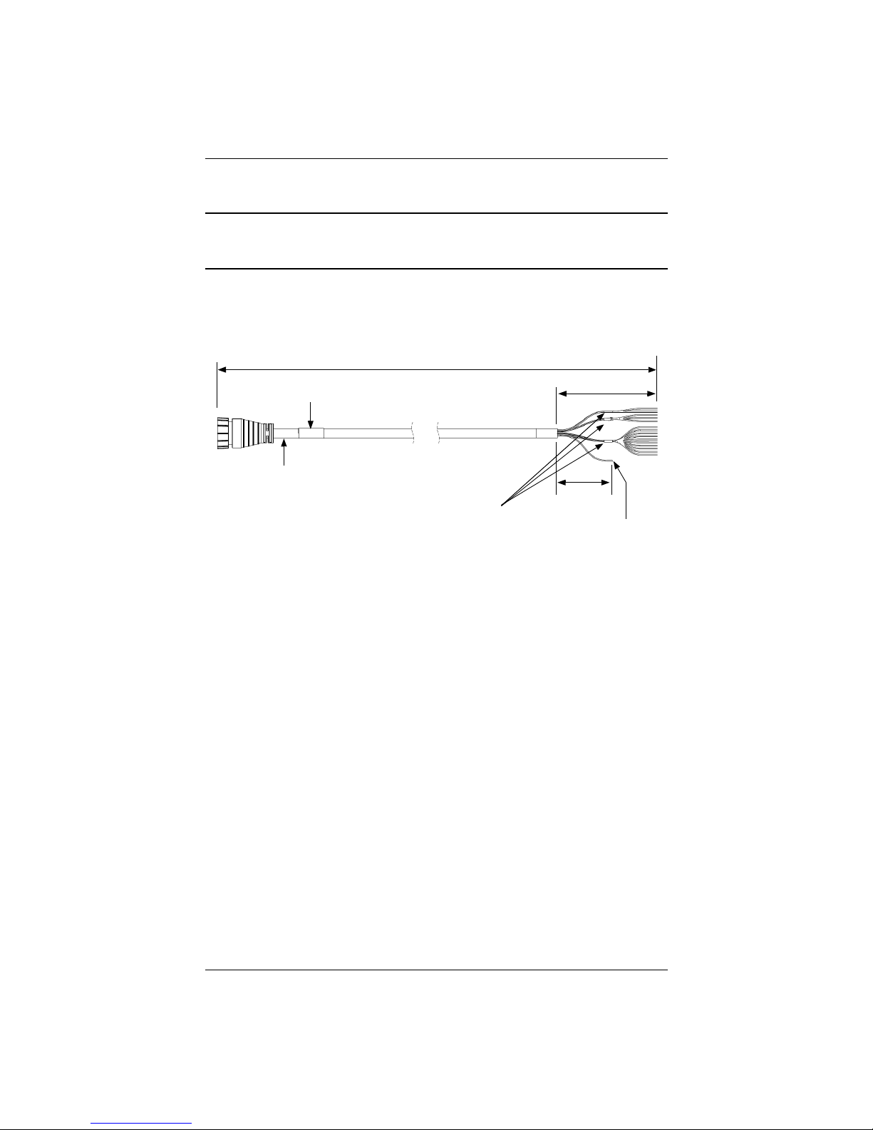
The V320 uses a single 15 m (49 ft) or 30 m (98 ft) cable for power and data input/
output.
Figure 2-9: Power/data cable, 15 m or 30 m
The receiver end of the cable is terminated with an environmentally sealed 18-pin
connection while the opposite end is unterminated and requires field stripping and
tinning.
Depending on the application and installation needs, you may need to shorten this
cable. However, if you require a longer cable run than 30 m, you can bring the cable
into a break-out box that incorporates terminal strips, within the vessel.
When lengthening the cable keep the following in mind:
• To lengthen the serial lines inside the vessel, use 20-gauge twisted pairs and
minimize the additional wire length.
• When lengthening the power input leads to the V320, ensure the additional
voltage drop is small enough that your power system can continue to power
the system above the minimum voltage of the system. Wire of 18-gauge or
larger should also be used.
• Minimize RS-232 cable length to ensure reliable communication
V320 GNSS Smart Antenna User Guide 24 PN 875-0351-0 Rev A1
Page 29
Chapter 2: Installation
Power/Data Cable Pinout Specifications
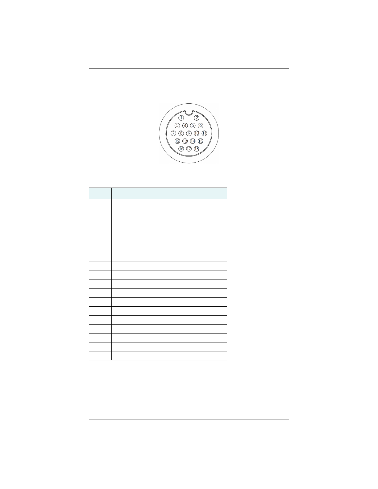
Figure 2-10 shows the power/data cable pin-out, while Table 2-3 shows the cable’s pinout specifications.
Figure 2-10: Power/data cable pin assignment
Table 2-3: Power/data cable pinout
Pin Function Wire Color
1 Power (+) Red
2 Power (-) Black
3 Port A Tx RS-232 Blue
4 Port A Rx RS-232 Black/blue stripe
5 Reserved
6 Port A Tx RS-422(+) Green
7 Port B Rx RS-422(+) Brown
8 Port B Rx RS-422(-) Black/brown stripe
9 Reserved
10 Drain Bare wire
11 Port A Tx RS-422(-) Green/black stripe
12 Signal ground Grey
13 Alarm White
14 Alarm White/red stripe
15 1 PPS(+) Orange
16 Port B Tx RS-422(+) Yellow
17 Port B Tx RS-422(-) Yellow/black stripe
18 1 PPS(-) Orange/black stripe
V320 GNSS Smart Antenna User Guide 25 PN 875-0351-0 Rev A1
Page 30
Chapter 2: Installation
Default Parameters
Table 2-4 and Table 2-5 provide details on the default port settings, available baud
rates, differential age, elevation mask, and default differential mode.
Note: Use the $JSAVE command to save changes you make to the V320’s
configuration for the changes to be present in subsequent power cycles.
Table 2-4: Default port settings
Port Baud Rate NMEA Messages Update Rate
Port A
(RS-232)
Port C
(RS-232)
Power
RED (+)
BLK (-)
Note: The default update rate for NMEA 0183 messages is 1 Hz. 10 Hz is the standard
maximum rate, but you can purchase a subscription to upgrade the output rate to 20 Hz.
Table 2-5: Default parameters
19200 GPGGA, GPVTG, GPGSV, GPZDA,
GPHDT, GPROT
19200 GPGGA, GPVTG, GPGSV, GPZDA,
GPHDT, GPROT
6 - 36 VDC
1 Hz
1 Hz
Unit Parameter Specification
V320 Max DGNSS age (correction age) 2700 seconds
Elevation mask 5°
Differential mode SBAS
V320 GNSS Smart Antenna User Guide 26 PN 875-0351-0 Rev A1
Page 31

Chapter 3: Understanding the V320
Chapter 3: Understanding the V320
GNSS Overview
V320 Overview
V320 GNSS Smart Antenna User Guide 27 PN 875-0351-0 Rev A1
Page 32

Chapter 3: Understanding the V320
GNSS Overview
For your convenience, the GNSS operation of the V320 features automatic operational
algorithms. When powered for the first time, the V320 performs a “cold start,” which
involves acquiring the available GNSS satellites in view and the SBAS differential
service.
If SBAS is not available in your area, an external source of RTCM SC-104 differential
corrections may be used. If you use an external source of correction data, it must
support an eight data bit, no parity, one stop bit configuration (8-N-1).
GNSS Operation
The GNSS receiver is always operating, regardless of the DGNSS mode of operation.
The following sections describe the general operation of the V320’s internal GNSS
receiver.
Note: Differential source and RTK status have no impact on heading, pitch, or roll.
They only have an impact on positioning and heave.
Automatic Tracking
The V320’s internal GNSS receiver automatically searches for GNSS satellites,
acquires the signals, and manages the navigation information required for positioning
and tracking.
Receiver Performance
The V320 works by finding four or more GNSS satellites in the visible sky. It uses
information from the satellites to compute a position within 2.5 m. Since there is
some error in the GNSS data calculations, the V320 also tracks a differential
correction. The V320 uses these corrections to improve its position accuracy to better
than 0.5 m 95% with SBAS, and better than 0.1 m 95% with Atlas.
There are two main aspects of GNSS receiver performance:
• Satellite acquisition
• Positioning and heading calculation
When the V320 is properly positioned, the satellites transmit coded information to the
antennas on a specific frequency. This allows the receiver to calculate a range to each
satellite from both antennas. GNSS is essentially a timing system. The ranges are
calculated by timing how long it takes for the signal to reach the GNSS antenna. The
GNSS receiver uses a complex algorithm incorporating satellite locations and ranges
to each satellite to calculate the geographic location and heading. Reception of any
four or more GNSS signals allows the receiver to compute three-dimensional
coordinates and a valid heading.
Differential Operation
The purpose of differential GNSS (DGNSS) is to remove the effects of selective
availability (SA), atmospheric errors, timing errors, and satellite orbit errors, while
enhancing system integrity.
Autonomous positioning capabilities of the V320 will result in positioning accuracies
of 2.5 m 95% of the time. To improve positioning quality to sub-meter levels, the V320
V320 GNSS Smart Antenna User Guide 28 PN 875-0351-0 Rev A1
Page 33

Chapter 3: Understanding the V320
is able to use differential corrections received through the internal SBAS demodulator,
externally-supplied RTCM corrections, and Atlas L-Band.
In addition to these differential services the V320 comes with the Athena RTK
activation, which enables 0.02 m positioning performance.
For more information on the differential services and the associated commands refer
to the Hemisphere GNSS Technical Reference (go to www.hgnss.com and click the
NSS Reference icon).
G
Automatic SBAS Tracking
The V320 automatically scans and tracks SBAS signals without the need to tune the
receiver. The V320 features two-channel tracking that provides an enhanced ability to
maintain a lock on an SBAS satellite when more than one satellite is in view. This
redundant tracking approach results in more consistent tracking of an SBAS signal in
areas where signal blockage of a satellite is possible.
Athena RTK
Athena RTK (Real time kinematic) technology is available on Eclipse-based GNSS
receivers. Athena RTK requires the use of two separate receivers: a stationary base
station (primary receiver) that broadcasts corrections over a wireless link to the rover
(secondary receiver). The localized corrections are processed on the rover to achieve
superior accuracy and repeatability. Performance testing has shown positioning
accuracy at the centimeter level.
Atlas L-Band
Atlas L-band corrections are available worldwide. With Atlas, the positioning accuracy
does not degrade as a function of distance to a base station, as the data content is not
composed of a single base station’s information, but an entire network’s information.
V320 GNSS Smart Antenna User Guide 29 PN 875-0351-0 Rev A1
Page 34
Chapter 3: Understanding the V320
Primary antenna
0.5 m baseline
V320 Overview
The V320 provides accurate and reliable heading and position information at high
update rates. To accomplish this task, the V320 uses a high performance GNSS
receiver and two antennas for GNSS signal processing. One antenna is designated as
the primary GNSS antenna and the other is the secondary GNSS antenna. Positions
computed by the V320 are referenced to the phase center of the primary GNSS
antenna. Heading data references the vector formed from the primary GNSS antenna
phase center to the secondary GNSS antenna phase center.
Fixed Baseline Moving Base Station RTK
The V320’s internal GNSS receiver uses both the L1/L2 GNSS C/A code and carrier
phase data to compute the location of the secondary GNSS antenna in relation to the
primary GNSS antenna with a very high sub-centimeter level of precision. The
technique of computing the location of the secondary GNSS antenna with respect to
the primary antenna, when the primary antenna is moving, is often referred to as
moving base station real time kinematic (or moving base station RTK).
Generally, RTK technology is very sophisticated and requires a significant number of
possible solutions to be analyzed where various combinations of integer numbers of
L1/L2 wavelengths to each satellite intersect within a certain search volume. The
integer number of wavelengths is often referred to as the “ambiguity” as they are
initially ambiguous at the start of the RTK solution.
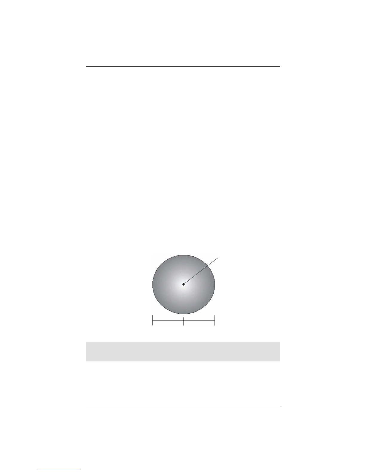
The V320 restricts the RTK solution by knowing that the secondary GNSS antenna is a
fixed distance from the primary GNSS antenna. The default value is 0.5 m. This is
called a fixed baseline and it defines the search volume of the secondary antenna as
the surface of a sphere with radius 0.5 m centered on the location of the primary
antenna (see Figure 3-1).
Note: The V320 moving base station algorithm only uses GNSS to calculate heading.
Differential and RTK corrections are not used in this calculation and will not affect
heading accuracy.
V320 GNSS Smart Antenna User Guide 30 PN 875-0351-0 Rev A1
Figure 3-1: Secondary antenna’s search volume
Page 35
Chapter 3: Understanding the V320
Tilt angle
GLONASS & BeiDou
The V320 is available in its base form as L1/L2 GPS, GLONASS and BeiDou. As the
number of available satellites increases, the ability to obtain and maintain a heading
solution increases. For a heading calculation, GPS, GLONASS and BeiDou satellites
are used interchangeably, as inter-system biases cancel inside the V320—this
translates into being able to work in more obstructed areas and maintain a GNSS
heading solution.
L2 Advantages
Compared to Hemisphere GNSS’ Crescent Vector technology, Eclipse Vector’s dual
frequency technology allows for:
• Longer range RTK
• Faster and more robustly computed GNSS heading solution
Supplemental Sensor
The V320 has an integrated gyro, which is enabled by default. The supplemental
sensor may be enabled or disabled. The supplemental sensor is mounted on the
printed circuit board inside the V320.
The sensors act to reduce the RTK search volume, which improves heading startup
and reacquisition times. This improves the reliability and accuracy of selecting the
correct heading solution by eliminating other possible, erroneous solutions.
The Hemisphere GNSS Technical Reference (go to www.hgnss.com and click the
NSS Reference icon) describes the commands and methodology required to
G
recalibrate, query, or change the sensors status.
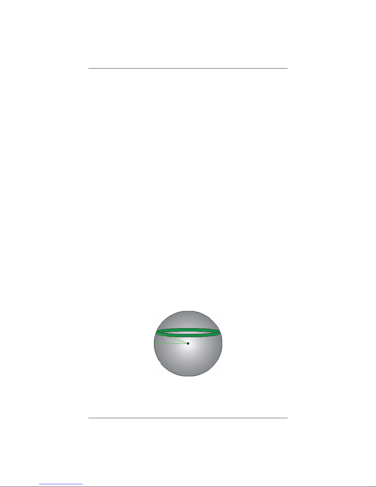
Tilt Aiding
The V320’s accelerometers (internal tilt sensors) are factory calibrated and enabled by
default. This constrains the RTK heading solution beyond the volume associated with
a fixed antenna separation. This is because the V320 knows the approximate
inclination of the secondary antenna with respect to the primary antenna. The search
space defined by the tilt sensor will be reduced to a horizontal ring on the sphere’s
surface by reducing the search volume. This considerably decreases startup and
reacquisition times (see Figure 3-2).
Figure 3-2: V320’s tilt aiding
V320 GNSS Smart Antenna User Guide 31 PN 875-0351-0 Rev A1
Page 36
Chapter 3: Understanding the V320
Gyro Aiding
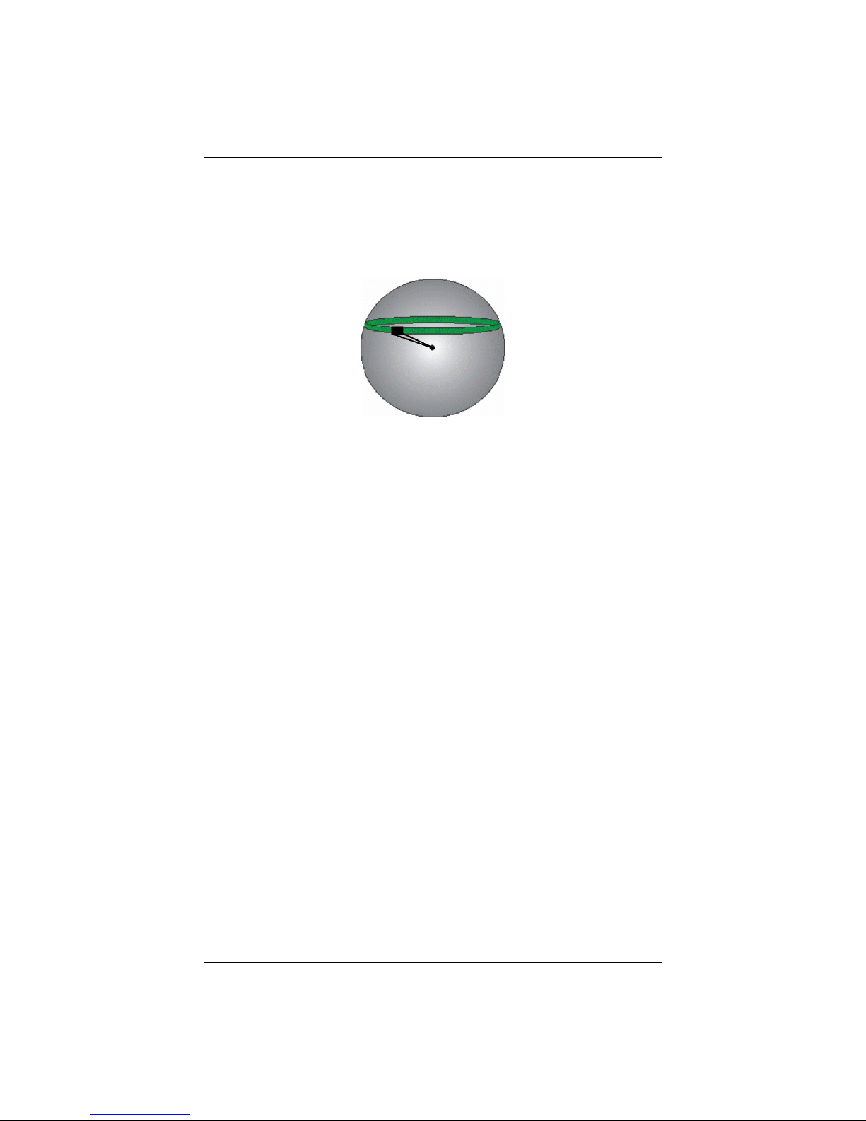
The V320’s internal gyro offers several benefits. It reduces the sensor volume for an
RTK solution. This shortens reacquisition times when a GNSS heading is lost because
the satellite signals were blocked. The gyro provides a relative change in angle since
the last computed heading, and, when used in conjunction with the tilt sensor, defines
the search space as a wedge-shaped location (see Figure 3-3).
Figure 3-3: V320’s gyro aiding
The gyro aiding accurately smooths the heading output and the rate of turn. It
provides an accurate substitute heading for a short period depending on the roll and
pitch of the vessel, ideally seeing the system through to reacquisition. The gyro
provides an alternate source of heading, accurate to within 1º per minute for up to
three minutes, in times of GNSS loss for either antenna. If the outage lasts longer than
three minutes, the gyro will have drifted too far and the V320 begins outputting null
fields in the heading output messages. There is no user control over the timeout
period of the gyro.
The gyro initializes itself at power up and during initialization, or you can calibrate it as
outlined in the Hemisphere GNSS Technical Reference (go to www.hgnss.com and
ick the GNSS Reference icon). For optimal performance, when the gyro is first
cl
initializing, the dynamics the gyro experiences during this warm-up period are similar
to the regular operating dynamics. For example, if you use the V320 on a high speed,
maneuverable craft, it is essential that when gyro aiding in the V320 is first turned on,
use it in an environment that has high dynamics for the first five to ten minutes
instead of sitting stationary.
With the gyro enabled, the gyro is also used to update the post HTAU smoothed
heading output from the moving base station RTK GNSS heading computation. This
means that if the HTAU value is increased while gyro aiding is enabled, there will be
little to no lag in heading output due to vehicle maneuvers. The Hemisphere GNSS
Technical Reference includes information on setting an appropriate HTAU value for the
application.
Time Constants
The V320 incorporates user-configurable time constants that can provide a degree of
smoothing to the heading, pitch, rate-of-turn (ROT), course-over-ground (COG), and
speed measurements. You can adjust these parameters depending on the expected
dynamics of the vessel. For example, increasing the time is reasonable if the vessel is
very large and is not able to turn quickly or would not pitch quickly. The resulting
values would have reduced “noise,” resulting in consistent values with time. However,
if the vessel is quick and nimble, increasing this value can create a lag in
measurements. Formulas for determining the level of smoothing are located in the
V320 GNSS Smart Antenna User Guide 32 PN 875-0351-0 Rev A1
Page 37

Chapter 3: Understanding the V320
Hemisphere GNSS Technical Reference (go to www.hgnss.com and click the GNSS
Reference icon). If you are unsure on how to set this value, it is best to be conservative
and leave it at the default setting.
Heading Time Constant
Use the $JATT,HTAU command to adjust the level of responsiveness of the true
heading measurement provided in the $GPHDT message. The default value of this
constant is 0.1 seconds of smoothing when the gyro is enabled. The gyro is enabled
by default, but can be turned off. By turning the gyro off, the equivalent default value
of the heading time constant would be 0.5 seconds of smoothing. This is not
automatically done and therefore you must manually enter it. Increasing the time
constant increases the level of heading smoothing and increases lag.
Pitch Time Constant
Use the $JATT,PTAU command to adjust the level of responsiveness of the pitch
measurement provided in the $PSAT,HPR message. The default value of this constant
is 0.5 seconds of smoothing. Increasing the time constant increases the level of pitch
smoothing and increases lag.
Rate-of-Turn (ROT) Time Constant
Use the $JATT,HRTAU command to adjust the level of responsiveness of the ROT
measurement provided in the $GPROT message. The default value of this constant is
2.0 seconds of smoothing. Increasing the time constant increases the level of ROT
smoothing.
Course-Over-Ground (COG) Time Constant
Use the $JATT,COGTAU command to adjust the level of responsiveness of the COG
measurement provided in the $GPVTG message. The default value of this constant is
0.0 seconds of smoothing. Increasing the time constant increases the level of COG
smoothing. COG is computed using only the primary GNSS antenna and its accuracy
depends upon the speed of the vessel (noise is proportional to 1/speed). This value is
invalid when the vessel is stationary.
Speed Time Constant
Use the $JATT,SPDTAU command to adjust the level of responsiveness of the speed
measurement provided in the $GPVTG message. The default value of this parameter
is 0.0 seconds of smoothing. Increasing the time constant increases the level of speed
measurement smoothing.
V320 GNSS Smart Antenna User Guide 33 PN 875-0351-0 Rev A1
Page 38

Chapter 3: Understanding the V320
V320 GNSS Smart Antenna User Guide 34 PN 875-0351-0 Rev A1
Page 39

Appendix A: Troubleshooting
Appendix A: Troubleshooting
V320 GNSS Smart Antenna User Guide 35 PN 875-0351-0 Rev A1
Page 40

Appendix A: Troubleshooting
Table A-1 provides troubleshooting for common problems.
Table A-1: Troubleshooting
Symptom Possible Solution
Receiver fails to power • Verify polarity of power leads
• Check integrity of power cable connectors
• Check power input voltage (6 to 36 VDC)
• Check current restrictions imposed by power source
(minimum available should be > 1.0 A)
No data from V320 • Check receiver power status to ensure the receiver is
Random data from
V320
No GNSS lock • Verify the V320 has a clear view of the sky
No SBAS lock • Verify the V320 has a clear view of the sky
powered (an ammeter can be used for this)
• Verify desired messages are activated (using
PocketMax or $JSHOW command in any terminal
program)
• Ensure the baud rate of the V320 matches that of the
receiving device
• Check integrity and connectivity of power and data
cable connections
• Verify the RTCM or binary messages are not being
output accidentally (send a $JSHOW command)
• Ensure the baud rate of the V320 matches that of the
remote device
• Potentially, the volume of data requested to be output
by the V320 could be higher than the current baud rate
supports (try using 19200 as the baud rate for all
devices or reduce the amount of data being output)
• Verify the lock status of GNSS satellites (this can be
done with PocketMax)
• Verify the lock status of SBAS satellites (this can be
done with PocketMax - monitor BER value)
• Set SBAS mode to automatic with the
$JWAASPRN,AUTO command
Note: SBAS lock is only possible if you are in an
appropriate SBAS region; currently, there is limited SBAS
availability in the southern hemisphere.
V320 GNSS Smart Antenna User Guide 36 PN 875-0351-0 Rev A1
Page 41

Table A-1: Troubleshooting (continued)
Symptom Possible Solution
No heading or incorrect
heading value
• Check CSEP value is fairly constant without varying
more than 1 cm (0.39 in)—larger variations may
indicate a high multipath environment and require
moving the receiver location
• Heading is from primary GNSS antenna to secondary
GNSS antenna, so the arrow on the underside of the
V320 should be directed to the bow side
• $JATT,SEARCH command forces the V320 to acquire a
new heading solution (unless gyro is enabled)
• Enable GYROAID to provide heading for up to three
minutes during GNSS signal loss
• Enable TILTAID to reduce heading search times
• Monitor the number of satellites and SNR values for
both antennas within PocketMax—at least four
satellites should have strong SNR values
• Potentially, the volume of data requested to be output
by the V320 could be higher than the current baud rate
supports (try using 19200 as the baud rate for all
devices or reduce the amount of data being output)
No DGNSS position in
external RTCM mode
• Verify the baud rate of the RTCM input port matches
the baud rate of the external source
• Verify the pinout between the RTCM source and the
RTCM input port (transmit from the source must go to
receive of the RTCM input port and grounds must be
connected)
• Ensure corrections are being transmitted to the correct
port—using the $JDIFF,PORTB command on Port A will
cause the receiver to expect the corrections to be input
through Port B
Appendix A: Troubleshooting
V320 GNSS Smart Antenna User Guide 37 PN 875-0351-0 Rev A1
Page 42

Appendix A: Troubleshooting
V320 GNSS Smart Antenna User Guide 38 PN 875-0351-0 Rev A1
Page 43

Appendix B: Technical Specifications
Appendix B: Technical Specifications
V320 GNSS Smart Antenna User Guide 39 PN 875-0351-0 Rev A1
Page 44
Appendix B: Technical Specifications
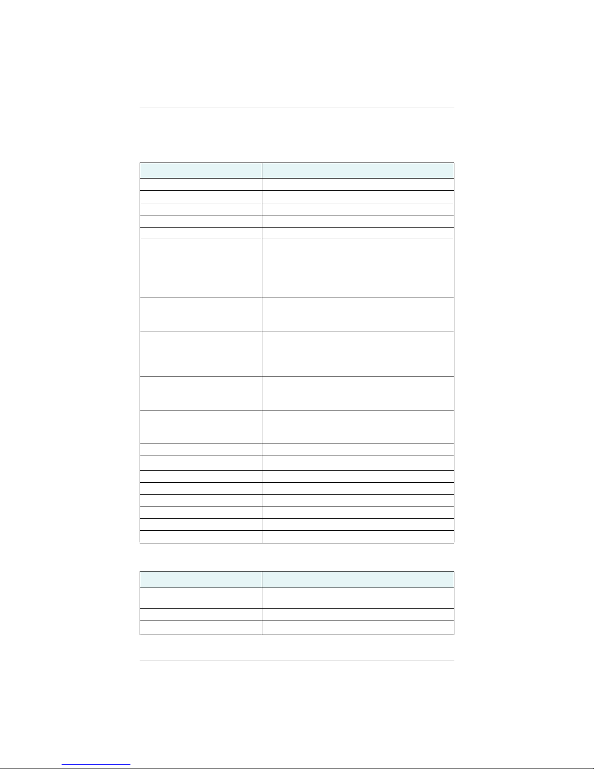
Table B-1 through Table B-5 provide the V320’s technical specifications and Table B-7
provides the V320’s certification information.
Table B-1: GNSS sensor specifications
Item Specification
Receiver type Vector GNSS RTK Receiver
Channels 744
GNSS sensitivity -142 dBm
SBAS tracking 3-channel, parallel tracking
Update rate 10 HZ standard, 20 Hz available by activation
Position accuracy
RMS (67%): Horizontal Vertical
Single Point: 1.2 m 2.5 m
SBAS (WAAS): 0.3 m 0.6 m
L-Band: 0.1 m 0.2 m
RTK: 10 mm + 1 ppm 20 mm + 2 ppm
Heading accuracy (RMS) < 0.17°
Normal operation: GNSS
Coasting (no GNSS): Gyro
Heave accuracy (RMS)
< 30 cm (DGNSS)
<10 cm (RTK)
Normal operation: GNSS
Coasting (no GNSS): None
Pitch accuracy < 1° RMS
Normal operation: GNSS
Coasting (no GNSS): Inertial sensor
Roll accuracy < 1° RMS using accelerometer
Normal operation: Inertial sensor
Coasting (no GNSS): Inertial sensor
Timing (1 PPS) accuracy 20 ns
Rate of turn
100°/s maximum
Cold start < 60 s typical (no almanac or RTC)
Warm start < 30 s typical (almanac and RTC)
Hot start < 10 s typical (almanac, RTC, and position)
Heading fix < 20 s typical (valid position)
Maximum speed 1,850 kph (999 kts)
Maximum altitude 18,288 m (60,00 0 ft)
Table B-2: Communication specifications
Item Specification
Serial ports 1 RS-232 (full-duplex)
Baud rates 4800, 9600, 19200, 38400
Correction I/O protocol
V320 GNSS Smart Antenna User Guide 40 PN 875-0351-0 Rev A1
2 RS-422 (1 full duplex, 1 half duplex)
RTCM SC-104, L-Dif™
5
Page 45
Appendix B: Technical Specifications
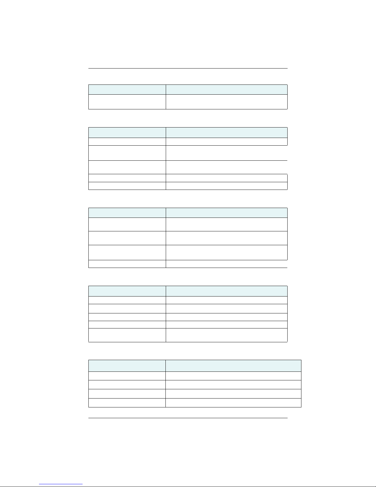
Table B-2: Communication specifications (continued)
Item Specification
Data I/O protocol
NMEA 0183, NMEA 2000, Hemisphere GNSS binary5,
L-Dif
Table B-3: Power specifications
Item Specification
Input voltage 6 to 36 VDC
Power consumption ~ 7 W nominal (GPS L1/L2 + GLONASS L1/L2 + BeiDou
B1/B2 + Atlas L-Band)
Current consumption ~ 0.51 A nominal (GPS L1/L2 + GLONASS L1/L2 +
BeiDou B1/B2 + Atlas L-Band)
Power isolation Isolated to enclosure
Reverse polarity protection Yes
Table B-4: Mechanical specifications
Item Specification
Enclosure UV resistant, white plastic, AES HW 600G,
non-corrosive, self extinguishing
Dimensions 66.3 L x 20.9 W x 14.6 H (cm)
26.1 L x 8.3 W x 5.8 H (in)
Weight V320
2.1 kg (4.6 lb)
Power/data connector 18-pin, environmentally sealed
Table B-5: Environmental specifications
Item Specification
Operating temperature -30°C to +70°C (-22°F to +158°F)
Storage temperature
-40°C to +85°C (-40°F to +185°F)
Humidity 95% non-condensing
Vibration IEC 60945
EMC CE (IEC 60945 Emissions and Immunity), FCC Part 15,
Subpart B, CISPR22
Table B-6: L-Band Sensor specifications
Item Specification
Receiver Type Single Channel
Channels 1530 to 1560 MHz
Sensitivity -130 dBm
Channel Spacing 5.0 KHz
V320 GNSS Smart Antenna User Guide 41 PN 875-0351-0 Rev A1
Page 46
Appendix B: Technical Specifications
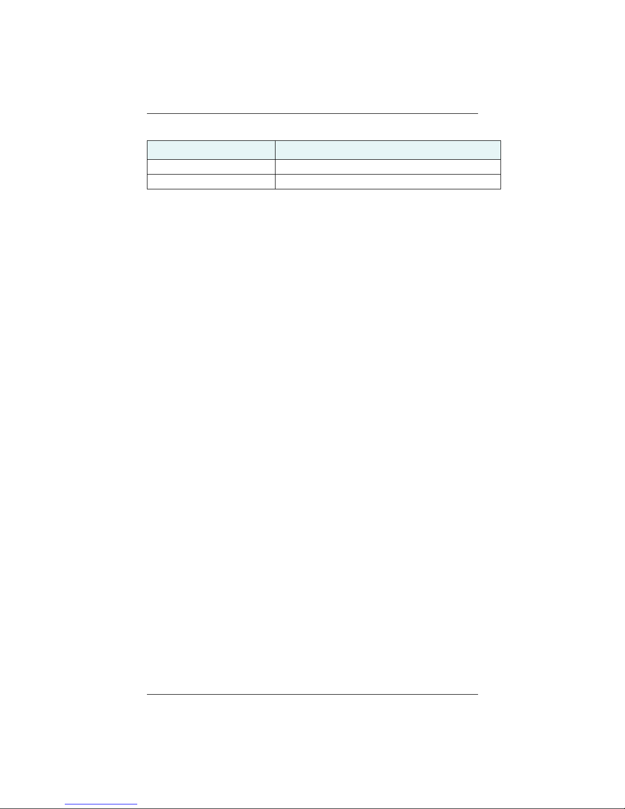
Table B-6: L-Band Sensor specifications
Item Specification
Satellite Selection Manual or Automatic
Reacquisition Time 15 sec (typical)
1
Depends on multipath environment, number of satellites in view, satellite geometry,
baseline length (for local services), and ionospheric activity
2
Depends on multipath environment, number of satellites in view, and satellite
geometry
3
Based on a 40 second time constant
4
This is the minimum safe distance measured when the product is placed in the
vicinity of the steering magnetic compass. The ISO 694 defines “vicinity” relative to
the compass as within 5 m (16.4 ft) separation.
5
Hemisphere GNSS proprietary
V320 GNSS Smart Antenna User Guide 42 PN 875-0351-0 Rev A1
Page 47

Index
Index
A
alignment 10
automatic
SBAS tracking 29
tracking 28
C
cable See power/data cable 1
certifications 41
communication specifications 41
connect
to a power source 23
to external devices 24
course over ground time constant 32
3
E
electrical isolation 23
environmental
considerations 6
specifications 41
environmental considerations 6
external devices 24
F
flush mount 13
G
GPHEV 8
GNSS
automatic SBAS tracking 29
automatic tracking 28
operation 28
overview 28
receiver performance 28
sensor specifications 40
GNSS reception 6
gyro aiding 32
H
heading time constant 33
heave 8
HRTAU 33
HTAU 33
L
long sight alignment 10
M
mechanical specifications 40
mounting
alignment 11
cable considerations 12
environmental considerations 6
flush mount 13
GNSS reception 6
location 6
orientation 8
parallel orientation 8
perpendicular orientation 8
pole mount 15
VHF interference 7
moving base station RTK 30
O
orientation for mounting 8
P
parallel mounting 8
part numbers 4
parts list 4
perpendicular mounting 8
pitch time constant 32
pole mount 15
power
connecting to a power source 23
considerations 23
electrical isolation 23
power specifications 41
PTAU 33
R
rate of turn (ROT) time constant 32
receiver performance 28
S
sensor specifications 40
short site alignment 10
SPDTAU 33
specifications
certifications 41
communication 41
environmental 41
GNSS sensor 40
mechanical 41
power 41
speed time constant 33
supplemental sensors 30
V320 GNSS Smart Antenna User Guide 43 PN 875-0351-0 Rev A1
Page 48

Index
T
tilt aiding 30
time constants 33
COGTAU 33
HRTAU 33
HTAU 33
PTAU 33
SPDTAU 33
tracking
automatic 28
automatic SBAS 29
troubleshooting 40
V
V320
gyro aiding 31
moving base station RTK 29
parts list 4
specifications 40
supplemental sensor 30
tilt aiding 30
time constants 32
VHF interference 7
V320 GNSS Smart Antenna User Guide 44 PN 875-0351-0 Rev A1
Page 49

End User License Agreement
IMPORTANT - This is an agreement (the “Agreement”) between you, the end purchaser (“Licensee”) and Hemisphere
GNSS Inc. (“Hemisphere”) which permits Licensee to use the Hemisphere software (the “Software”) that accompanies
this Agreement. This Software may be licensed on a standalone basis or may be embedded in a Product. Please read and
ensure that you understand this Agreement before installing or using the Software Update or using a Product.
In this agreement any product that has Software embedded in it at the time of sale to the Licensee shall be referred to as a
“Product”. As well, in this Agreement, the use of a Product shall be deemed to be use of the Software which is embedded
in the Product.
BY INSTALLING OR USING THE SOFTWARE UPDATE OR THE PRODUCT, LICENSEE THEREBY AGREES TO BE LEGALLY
BOUND BY THE TERMS OF THIS AGREEMENT. IF YOU DO NOT AGREE TO THESE TERMS, (I) DO NOT INSTALL OR USE
THE SOFTWARE, AND (II) IF YOU ARE INSTALLING AN UPDATE TO THE SOFTWARE, DO NOT INSTALL THE UPDATE AND
PROMPTLY DESTROY IT.
HEMISPHERE PROVIDES LIMITED WARRANTIES IN RELATION TO THE SOFTWARE. AS WELL, THOSE WHO USE THE
EMBEDDED SOFTWARE DO SO AT THEIR OWN RISK. YOU SHOULD UNDERSTAND THE IMPORTANCE OF THESE AND
OTHER LIMITATIONS SET OUT IN THIS AGREEMENT BEFORE INSTALLING OR USING THE SOFTWARE OR THE PRODUCT.
1. LICENSE. Hemisphere hereby grants to Licensee a non-transferable and non-exclusive license to use the Software
as embedded in a Product and all Updates (collectively the “Software”), solely in binary executable form.
2. RESTRICTIONS ON USE. Licensee agrees that Licensee and its employees will not directly or indirectly, in any
manner whatsoever:
a. install or use more copies of the Software than the number of copies that have been licensed;
b. use or install the Software in connection with any product other than the Product the Software was intended
to be used or installed on as set out in the documentation that accompanies the Software.
c. copy any of the Software or any written materials for any purpose except as part of Licensee's normal backup
processes;
d. modify or create derivative works based on the Software;
e. sub-license, rent, lease, loan or distribute the Software;
f. permit any third party to use the Software;
g. use or operate Product for the benefit of any third party in any type of service outsourcing, application service,
provider service or service bureau capacity;
h. reverse engineer, decompile or disassemble the Software or otherwise reduce it to a human perceivable form;
i. Assign this Agreement or sell or otherwise transfer the Software to any other party except as part of the sale
3. UPDATES. At Hemisphere's discretion Hemisphere may make Updates available to Licensee. An update
4. SUPPORT. Hemisphere may make available directly or through its authorized dealers telephone and email support
5. BACKUPS AND RECOVERY. Licensee shall back-up all data used, created or stored by the Software on a regular
6. OWNERSHIP. Hemisphere and its suppliers own all rights, title and interest in and to the Software and related
7. TRADEMARKS. “Hemisphere GNSS”, “Outback Guidance”, “BEELINE”, “Eclipse”, “Eclipse” and the associated
8. LIMITED WARRANTY. Hemisphere warrants solely to the Licensee, subject to the exclusions and procedures set
9. WARRANTY EXCLUSIONS. The warranty set forth in Section (8) will not apply to any deficiencies caused by (a)
or transfer of the whole Product.
(“Update”) means any update to the Software that is made available to Licensee including error corrections,
enhancements and other modifications. Licensee may access, download and install Updates during the Warranty
Period only. All Updates that Licensee downloads, installs or uses shall be deemed to be Software and subject to this
Agreement. Hemisphere reserves the right to modify the Product without any obligation to notify, supply or install
any improvements or alterations to existing Software.
for the Software. Contact Hemisphere to find the authorized dealer near you. As well, Hemisphere may make
available user and technical documentation regarding the Software. Hemisphere reserves the right to reduce and
limit access to such support at any time.
basis as necessary to enable proper recovery of the data and related systems and processes in the event of a
malfunction in the Software or any loss or corruption of data caused by the Software. Licensee shall assume all risks
of loss or damage for any failure to comply with the foregoing.
materials, including all intellectual property rights. The Software is licensed to Licensee, not sold.
logos are trademarks of Hemisphere. Other trademarks are the property of their respective owners. Licensee may
not use any of these trademarks without the consent of their respective owners.
forth herein below, that for a period of one (1) year from the original date of purchase of the Product in which it is
embedded (the “Warranty Period”), the Software, under normal use and maintenance, will conform in all material
respects to the documentation provided with the Software and any media will be free of defects in materials and
workmanship. For any Update, Hemisphere warrants, for 90 days from performance or delivery, or for the balance of
the original Warranty Period, whichever is greater, that the Update, under normal use and maintenance, will
conform in all material respects to the documentation provided with the Update and any media will be free of
defects in materials and workmanship. Notwithstanding the foregoing, Hemisphere does not warrant that the
Software will meet Licensee's requirements or that its operation will be error free.
the Product not being used as described in the documentation supplied to Licensee, (b) the Software having been
altered, modified or converted in any way by anyone other than Hemisphere approved by Hemisphere, (c) any
malfunction of Licensee's equipment or other software, or (d) damage occurring in transit or due to any accident,
abuse, misuse, improper installation, lightning (or other electrical discharge) or neglect other than that caused by
Hemisphere. Hemisphere GNSS does not warrant or guarantee the precision or accuracy of positions obtained
when using the Software (whether standalone or embedded in a Product). The Product and the Software is not
intended and should not be used as the primary means of navigation or for use in safety of life applications. The
Page 50

potential positioning and navigation accuracy obtainable with the Software as stated in the Product or Software
documentation serves to provide only an estimate of achievable accuracy based on specifications provided by the
US Department of Defense for GNSS positioning and DGNSS service provider performance specifications, where
applicable.
10. WARRANTY DISCLAIMER. EXCEPT AS EXPRESSLY SET OUT IN THIS AGREEMENT, HEMISPHERE MAKES NO
REPRESENTATION, WARRANTY OR CONDITION OF ANY KIND TO LICENSEE, WHETHER VERBAL OR WRITTEN
AND HEREBY DISCLAIMS ALL REPRESENTATIONS, WARRANTIES AND CONDITIONS OF ANY KIND INCLUDING
FITNESS FOR A PARTICULAR PURPOSE, MERCHANTABILITY, ACCURACY, RELIABILITY OR THAT THE USE OF THE
SOFTWARE WILL BE UNINTERRUPTED OR ERROR-FREE AND HEREBY DISCLAIMS ALL REPRESENTATIONS,
WARRANTIES AND CONDITIONS ARISING AS A RESULT OF CUSTOM, USAGE OR TRADE AND THOSE ARISING
UNDER STATUTE.
11. LIMITS ON WARRANTY DISCLAIMER. Some jurisdictions do not allow the exclusion of implied warranties or
conditions, so some of the above exclusions may not apply to Licensee. In that case, any implied warranties or
conditions which would then otherwise arise will be limited in duration to ninety (90) days from the date of the
license of the Software or the purchase of the Product. The warranties given herein give Licensee specific legal rights
and Licensee may have other rights which may vary from jurisdiction to jurisdiction.
12. CHANGE TO WARRANTY. No employee or agent of Hemisphere is authorized to change the warranty provided or
the limitation or disclaimer of warranty provisions. All such changes will only be effective if pursuant to a separate
agreement signed by senior officers of the respective parties.
13. WARRANTY CLAIM. In the event Licensee has a warranty claim Licensee must first check for and install all
Updates that are made available. The warranty will not otherwise be honored. Proof of purchase may be required.
Hemisphere does not honor claims asserted after the end of the Warranty Period.
14. LICENSEE REMEDIES. In all cases which involve a failure of the Software to conform in any material respect to the
documentation during the Warranty Period or a breach of a warranty, Hemisphere's sole obligation and liability, and
Licensee's sole and exclusive remedy, is for Hemisphere, at Hemisphere's option, to (a) repair the Software, (b)
replace the Software with software conforming to the documentation, or (c) if Hemisphere is unable, on a
reasonable commercial basis, to repair the Software or to replace the Software with conforming software within
ninety (90) days, to terminate this Agreement and thereafter Licensee shall cease using the Software. Hemisphere
will also issue a refund for the price paid by Licensee less an amount on account of amortization, calculated on a
straight-line basis over a deemed useful life of three (3) years.
15. LIMITATION OF LIABILITY. IN NO EVENT WILL HEMISPHERE BE LIABLE TO LICENSEE FOR ANY INCIDENTAL,
CONSEQUENTIAL, SPECIAL OR INDIRECT DAMAGES INCLUDING ARISING IN RELATION TO ANY LOSS OF DATA,
INCOME, REVENUE, GOODWILL OR ANTICIPATED SAVINGS EVEN IF HEMISPHERE HAS BEEN INFORMED OF THE
POSSIBILITY OF SUCH LOSS OR DAMAGE. FURTHER, IN NO EVENT WILL HEMISPHERE'S TOTAL CUMULATIVE
LIABILITY HEREUNDER, FROM ALL CAUSES OF ACTION OF ANY KIND, EXCEED THE TOTAL AMOUNT PAID BY
LICENSEE TO HEMISPHERE TO PURCHASE THE PRODUCT. THIS LIMITATION AND EXCLUSION APPLIES
IRRESPECTIVE OF THE CAUSE OF ACTION, INCLUDING BUT NOT LIMITED TO BREACH OF CONTRACT,
NEGLIGENCE, STRICT LIABILITY, TORT, BREACH OF WARRANTY, MISREPRESENTATION OR ANY OTHER LEGAL
THEORY AND WILL SURVIVE A FUNDAMENTAL BREACH.
16. LIMITS ON LIMITATION OF LIABILITY. Some jurisdictions do not allow for the limitation or exclusion of liability for
incidental or consequential damages, so the above limitation or exclusion may not apply to Licensee and Licensee
may also have other legal rights which may vary from jurisdiction to jurisdiction.
17. BASIS OF BARGAIN. Licensee agrees and acknowledges that Hemisphere has set its prices and the parties have
entered into this Agreement in reliance on the limited warranties, warranty disclaimers and limitations of liability set
forth herein, that the same reflect an agreed-to allocation of risk between the parties (including the risk that a
remedy may fail of its essential purpose and cause consequential loss), and that the same forms an essential basis
of the bargain between the parties. Licensee agrees and acknowledges that Hemisphere would not have been able
to sell the Product at the amount charged on an economic basis without such limitations.
18. PROPRIETARY RIGHTS INDEMNITY. Hemisphere shall indemnify, defend and hold harmless Licensee from and
against any and all actions, claims, demands, proceedings, liabilities, direct damages, judgments, settlements, fines,
penalties, costs and expenses, including royalties and attorneys' fees and related costs, in connection with or arising
out of any actual infringement of any third party patent, copyright or other intellectual property right by the Software
or by its use, in accordance with this Agreement and documentation, PROVIDED THAT: (a) Hemisphere has the right
to assume full control over any action, claim, demand or proceeding, (b) Licensee shall promptly notify Hemisphere
of any such action, claim, demand, or proceeding, and (c) Licensee shall give Hemisphere such reasonable
assistance and tangible material as is reasonably available to Licensee for the defense of the action, claim, demand
or proceeding. Licensee shall not settle or compromise any of same for which Hemisphere has agreed to assume
responsibility without Hemisphere's prior written consent. Licensee may, at its sole cost and expense, retain
separate counsel from the counsel utilized or retained by Hemisphere.
19. INFRINGEMENT. If use of the Software may be enjoined due to a claim of infringement by a third party then, at its
sole discretion and expense, Hemisphere may do one of the following: (a) negotiate a license or other agreement so
that the Product is no longer subject to such a potential claim, (b) modify the Product so that it becomes noninfringing, provided such modification can be accomplished without materially affecting the performance and
functionality of the Product, (c) replace the Software, or the Product, with non-infringing software, or product, of
equal or better performance and quality, or (d) if none of the foregoing can be done on a commercially reasonable
basis, terminate this license and Licensee shall stop using the Product and Hemisphere shall refund the price paid by
Licensee less an amount on account of amortization, calculated on a straight-line basis over a deemed useful life of
three (3) years.
The foregoing sets out the entire liability of Hemisphere and the sole obligations of Hemisphere to Licensee in
respect of any claim that the Software or its use infringes any third party rights.
20. INDEMNIFICATION. Except in relation to an infringement action, Licensee shall indemnify and hold Hemisphere
harmless from any and all claims, damages, losses, liabilities, costs and expenses (including reasonable fees of
lawyers and other professionals) arising out of or in connection with Licensee's use of the Product, whether direct or
indirect, including without limiting the foregoing, loss of data, loss of profit or business interruption.
Page 51

21. TERMINATION. Licensee may terminate this Agreement at any time without cause. Hemisphere may terminate this
Agreement on 30 days notice to Licensee if Licensee fails to materially comply with each provision of this
Agreement unless such default is cured within the 30 days. Any such termination by a party shall be in addition to
and without prejudice to such rights and remedies as may be available, including injunction and other equitable
remedies. Upon receipt by Licensee of written notice of termination from Hemisphere or termination by Licensee,
Licensee shall at the end of any notice period (a) cease using the Software; and (b) return to Hemisphere (or destroy
and provide a certificate of a Senior Officer attesting to such destruction) the Software and all related material and
any magnetic or optical media provided to Licensee. The provisions of Sections 6), 7), 8), 9), 10), 15), 21), 26) and 27)
herein shall survive the expiration or termination of this Agreement for any reason.
22. EXPORT RESTRICTIONS. Licensee agrees that Licensee will comply with all export control legislation of Canada,
the United States, Australia and any other applicable country's laws and regulations, whether under the Arms
Export Control Act, the International Traffic in Arms Regulations, the Export Administration Regulations, the
regulations of the United States Departments of Commerce, State, and Treasury, or otherwise as well as the export
control legislation of all other countries.
23. PRODUCT COMPONENTS. The Product may contain third party components. Those third party components may
be subject to additional terms and conditions. Licensee is required to agree to those terms and conditions in order to
use the Product.
24. FORCE MAJEURE EVENT. Neither party will have the right to claim damages as a result of the other's inability to
perform or any delay in performance due to unforeseeable circumstances beyond its reasonable control, such as
labor disputes, strikes, lockouts, war, riot, insurrection, epidemic, Internet virus attack, Internet failure, supplier
failure, act of God, or governmental action not the fault of the non-performing party.
25. FORUM FOR DISPUTES. The parties agree that the courts located in Calgary, Alberta, Canada and the courts of
appeal there from will have exclusive jurisdiction to resolve any disputes between Licensee and Hemisphere
concerning this Agreement or Licensee's use or inability to use the Software and the parties hereby irrevocably
agree to attorn to the jurisdiction of those courts. Notwithstanding the foregoing, either party may apply to any court
of competent jurisdiction for injunctive relief.
26. APPLICABLE LAW. This Agreement shall be governed by the laws of the Province of Alberta, Canada, exclusive of
any of its choice of law and conflicts of law jurisprudence.
27. CISG. The United Nations Convention on Contracts for the International Sale of Goods will not apply to this
Agreement or any transaction hereunder.
28. GENERAL. This is the entire agreement between Licensee and Hemisphere relating to the Product and Licensee's
use of the same, and supersedes all prior, collateral or contemporaneous oral or written representations, warranties
or agreements regarding the same. No amendment to or modification of this Agreement will be binding unless in
writing and signed by duly authorized representatives of the parties. Any and all terms and conditions set out in any
correspondence between the parties or set out in a purchase order which are different from or in addition to the
terms and conditions set forth herein, shall have no application and no written notice of same shall be required. In
the event that one or more of the provisions of this Agreement is found to be illegal or unenforceable, this
Agreement shall not be rendered inoperative but the remaining provisions shall continue in full force and effect.
Page 52

Warranty Notice
COVERED PRODUCTS: This warranty covers all products manufactured by Hemisphere GNSS and purchased by the
end purchaser (the “Products”), unless otherwise specifically and expressly agreed in writing by Hemisphere GNSS.
LIMITED WARRANTY: Hemisphere GNSS warrants solely to the end purchaser of the Products, subject to the exclusions
and procedures set forth below, that the Products sold to such end purchaser and its internal components shall be free,
under normal use and maintenance, from defects in materials, and workmanship and will substantially conform to
Hemisphere GNSS’ applicable specifications for the Product, for a period of 12 months from delivery of such Product to
such end purchaser (the”Warranty Period”). Repairs and replacement components for the Products are warranted, subject
to the exclusions and procedures set forth below, to be free, under normal use and maintenance, from defects in material
and workmanship, and will substantially conform to Hemisphere Gneiss's applicable specifications for the Product, for 90
days from performance or delivery, or for the balance of the original Warranty Period, whichever is greater.
EXCLUSION OF ALL OTHER WARRANTIES. The LIMITED WARRANTY shall apply only if the Product is properly and
correctly installed, configured, interfaced, maintained, stored, and operated in accordance with Hemisphere GNSS’s
relevant User’s Manual and Specifications, AND the Product is not modified or misused. The Product is provided “AS IS”
and the implied warranties of MERCHANTABILITY and FITNESS FOR A PARTICULAR PURPOSE and ALL OTHER
WARRANTIES, express, implied or arising by statute, by course of dealing or by trade usage, in connection with the
design, sale, installation, service or use of any products or any component thereof, are EXCLUDED from this transaction
and shall not apply to the Product. The LIMITED WARRANTY is IN LIEU OF any other warranty, express or implied,
including but not limited to, any warranty of MERCHANTABILITY or FITNESS FOR A PARTICULAR PURPOSE, title, and noninfringement.
LIMITATION OF REMEDIES. The purchaser’s EXCLUSIVE REMEDY against Hemisphere GNSS shall be, at Hemisphere
GNSS’s option, the repair or replacement of any defective Product or components thereof. The purchaser shall notify
Hemisphere GNSS or a Hemisphere GNSS’s approved service center immediately of any defect. Repairs shall be made
through a Hemisphere GNSS approved service center only. Repair, modification or service of Hemisphere GNSS products
by any party other than a Hemisphere GNSS approved service center shall render this warranty null and void. The remedy
in this paragraph shall only be applied in the event that the Product is properly and correctly installed, configured,
interfaced, maintained, stored, and operated in accordance with Hemisphere GNSS’s relevant User’s Manual and
Specifications, AND the Product is not modified or misused. NO OTHER REMEDY (INCLUDING, BUT NOT LIMITED TO,
SPECIAL, INDIRECT, INCIDENTAL, CONSEQUENTIAL OR CONTINGENT DAMAGES FOR LOST PROFITS, LOST SALES,
INJURY TO PERSON OR PROPERTY, OR ANY OTHER INCIDENTAL OR CONSEQUENTIAL LOSS) SHALL BE AVAILABLE TO
PURCHASER, even if Hemisphere GNSS has been advised of the possibility of such damages. Without limiting the
foregoing, Hemisphere GNSS shall not be liable for any damages of any kind resulting from installation, use, quality,
performance or accuracy of any Product.
HEMISPHERE IS NOT RESPONSIBLE FOR PURCHASER’S NEGLIGENCE OR UNAUTHORIZED USES OF THE
PRODUCT. IN NO EVENT SHALL HEMISPHERE GNSS BE IN ANY WAY RESPONSIBLE FOR ANY DAMAGES RESULTING
FROM PURCHASER’S OWN NEGLIGENCE, OR FROM OPERATION OF THE PRODUCT IN ANY WAY OTHER THAN AS
SPECIFIED IN HEMISPHERE GNSS’S RELEVANT USER’S MANUAL AND SPECIFICATIONS. Hemisphere GNSS is NOT
RESPONSIBLE for defects or performance problems resulting from (1) misuse, abuse, improper installation, neglect of
Product; (2) the utilization of the Product with hardware or software products, information, data, systems, interfaces or
devices not made, supplied or specified by Hemisphere GNSS; (3) the operation of the Product under any specification
other than, or in addition to, the specifications set forth in Hemisphere GNSS’s relevant User’s Manual and Specifications;
(4) damage caused by accident or natural events, such as lightning (or other electrical discharge) or fresh/salt water
immersion of Product; (5) damage occurring in transit; (6) normal wear and tear; or (7) the operation or failure of operation
of any satellite-based positioning system or differential correction service; or the availability or performance of any
satellite-based positioning signal or differential correction signal.
THE PURCHASER IS RESPONSIBLE FOR OPERATING THE VEHICLE SAFELY. The purchaser is solely responsible
for the safe operation of the vehicle used in connection with the Product, and for maintaining proper system control
settings. UNSAFE DRIVING OR SYSTEM CONTROL SETTINGS CAN RESULT IN PROPERTY DAMAGE, INJURY, OR DEATH.
The purchaser is solely responsible for his/her safety and for the safety of others. The purchaser is solely responsible for
maintaining control of the automated steering system at all times. THE PURCHASER IS SOLELY RESPONSIBLE FOR
ENSURING THE PRODUCT IS PROPERLY AND CORRECTLY INSTALLED, CONFIGURED, INTERFACED, MAINTAINED,
STORED, AND OPERATED IN ACCORDANCE WITH HEMISPHERE GNSS’S RELEVANT USER’S MANUAL AND
SPECIFICATIONS. Hemisphere GNSS does not warrant or guarantee the positioning and navigation precision or accuracy
obtained when using Products. Products are not intended for primary navigation or for use in safety of life applications.
The potential accuracy of Products as stated in Hemisphere GNSS literature and/or Product specifications serves to
provide only an estimate of achievable accuracy based on performance specifications provided by the satellite service
operator (i.e. US Department of Defense in the case of GNSS) and differential correction service provider. Hemisphere
GNSS reserves the right to modify Products without any obligation to notify, supply or install any improvements or
alterations to existing Products.
GOVERNING LAW. This agreement and any disputes relating to, concerning or based upon the Product shall be
governed by and interpreted in accordance with the laws of the State of Arizona.
OBTAINING WARRANTY SERVICE. In order to obtain warranty service, the end purchaser must bring the Product to a
Hemisphere GNSS approved service center along with the end purchaser's proof of purchase. Hemisphere GNSS does not
warrant claims asserted after the end of the warranty period. For any questions regarding warranty service or to obtain
information regarding the location of any of Hemisphere GNSS approved service center, contact Hemisphere GNSS at the
following address:
Hemisphere GNSS
8515 East Anderson Drive, Suite A
Scottsdale, AZ 85255
Phone: 480-348-6380 Fax: 480-270-5070
[email protected]
www.hgnss.com
Page 53
 Loading...