

Page 1
Vector H321 GNSS Compass Module
Integrator Guide
Part No. 875-0345-0 Rev. A1
Page 2

This device complies with part 15 of the FCC Rules. Operation is subject to the following two
conditions:
(1) This device may not cause harmful interference, and
(2) this device must accept any interference received, including interference that may cause
undesired operation.
Copyright Notice
Copyright Hemisphere GNSS, Inc. (2014). All rights reserved.
No part of this manual may be reproduced, transmitted, transcribed, stored in a retrieval system or
translated into any language or computer language, in any form or by any means, electronic,
mechanical, magnetic, optical, chemical, manual or otherwise, without the prior written
permission of Hemisphere GNSS.
Trademarks
Hemisphere GNSS®, the Hemisphere GNSS logo, COASTTM, Crescent®, EclipseTM, e-Dif®, L-DifTM,
miniEclipseTM, PocketMAX PCTM, PocketMAXTM, PocketMax3TM, S320TM, SBX-4TM, SureTrack®,
VectorTM, XF1TM, and XF2TM are proprietary trademarks of Hemisphere GNSS, Inc. Other
trademarks are the properties of their respective owners.
Patents
Hemisphere GNSS products may be covered by one or more of the following patents:
U.S. Patents Australia Patents
6111549 6876920 7400956 8000381 8214111 2002244539
6397147 7142956 7429952 8018376 8217833 2002325645
6469663 7162348 7437230 8085196 8265826 2004320401
6501346 7277792 7460942 8102325 8271194
6539303 7292185 7689354 8138970 8307535
6549091 7292186 7808428 8140223 8311696
6711501 7373231 7835832 8174437 8334804
6744404 7388539 7885745 8184050 RE41358
6865465 7400294 7948769 8190337
Other U.S. and foreign patents pending.
Notice to Customers
Contact your local dealer for technical assistance. To find the authorized dealer near you:
Hemisphere GNSS, Inc.
8444 N 90th St, Suite 120
Scottsdale, AZ 85258 USA
Phone: (480) 348-6380
Fax: (480) 270-5070
[email protected]
www.hemispheregnss.com
Technical Support
If you need to contact Hemisphere GNSS Technical Support:
Hemisphere GNSS, Inc.
8444 N 90th St, Suite 120
Scottsdale, AZ 85258 USA
Phone: (480) 348-6380
Fax: (480) 270-5070
Documentation Feedback
Hemisphere GNSS is committed to the quality and continuous improvement of our products and
services. We urge you to provide Hemisphere GNSS with any feedback regarding this guide by
writing to the following email address: [email protected].
Page 3

Page 4

H321Contents
Chapter 1 Introduction . . . . . . . . . . . . . . . . . . . . . . . . . . . . . . 1
Overview . . . . . . . . . . . . . . . . . . . . . . . . . . . . . . . . . . . . . . . . . . . . . . . 2
What’s Included . . . . . . . . . . . . . . . . . . . . . . . . . . . . . . . . . . . . . . . . . 2
H321 Integration . . . . . . . . . . . . . . . . . . . . . . . . . . . . . . . . . . . . . . . . . 4
H321 Features . . . . . . . . . . . . . . . . . . . . . . . . . . . . . . . . . . . . . . . . . . . 4
Configuring the H321 . . . . . . . . . . . . . . . . . . . . . . . . . . . . . . . . . . . . . 5
NMEA 0183 Message Interface . . . . . . . . . . . . . . . . . . . . . . . . . . . . . 5
Binary Message Interface . . . . . . . . . . . . . . . . . . . . . . . . . . . . . . . . . 5
Using PocketMax to Communicate with the H321 . . . . . . . . . . . . . 5
Chapter 2 Board Overview . . . . . . . . . . . . . . . . . . . . . . . . . . . 7
Mechanical Layout . . . . . . . . . . . . . . . . . . . . . . . . . . . . . . . . . . . . . . . 8
Connectors . . . . . . . . . . . . . . . . . . . . . . . . . . . . . . . . . . . . . . . . . . . . . 9
Mounting Options . . . . . . . . . . . . . . . . . . . . . . . . . . . . . . . . . . . . . . 10
Direct Electrical Connection Method . . . . . . . . . . . . . . . . . . . 10
Indirect Electrical Connection (Cable) Method . . . . . . . . . . . 10
Header and Pinouts . . . . . . . . . . . . . . . . . . . . . . . . . . . . . . . . . . . . . 11
Signals . . . . . . . . . . . . . . . . . . . . . . . . . . . . . . . . . . . . . . . . . . . . . . . 14
RF Input . . . . . . . . . . . . . . . . . . . . . . . . . . . . . . . . . . . . . . . . . . . 14
Serial Ports . . . . . . . . . . . . . . . . . . . . . . . . . . . . . . . . . . . . . . . . 14
Communication Port D . . . . . . . . . . . . . . . . . . . . . . . . . . . . . . 14
USB Ports . . . . . . . . . . . . . . . . . . . . . . . . . . . . . . . . . . . . . . . . . 14
LED Indicators . . . . . . . . . . . . . . . . . . . . . . . . . . . . . . . . . . . . . 17
1PPS Timing Signal . . . . . . . . . . . . . . . . . . . . . . . . . . . . . . . . . 17
Event Marker Input . . . . . . . . . . . . . . . . . . . . . . . . . . . . . . . . . 17
Grounds . . . . . . . . . . . . . . . . . . . . . . . . . . . . . . . . . . . . . . . . . . 18
Speed Radar Output . . . . . . . . . . . . . . . . . . . . . . . . . . . . . . . . 18
Shielding . . . . . . . . . . . . . . . . . . . . . . . . . . . . . . . . . . . . . . . . . . . . . . 19
Receiver Mounting . . . . . . . . . . . . . . . . . . . . . . . . . . . . . . . . . . . . . . 19
Thermal Concerns . . . . . . . . . . . . . . . . . . . . . . . . . . . . . . . . . . . . . . 19
Chapter 3 Operation . . . . . . . . . . . . . . . . . . . . . . . . . . . . . . . 21
Powering the H321 . . . . . . . . . . . . . . . . . . . . . . . . . . . . . . . . . . . . . . 22
Communicating with the H321 . . . . . . . . . . . . . . . . . . . . . . . . . . . . 22
Configuring the H321 . . . . . . . . . . . . . . . . . . . . . . . . . . . . . . . . . . . . 22
Firmware . . . . . . . . . . . . . . . . . . . . . . . . . . . . . . . . . . . . . . . . . . . . . . 23
Configuring the Data Message Output . . . . . . . . . . . . . . . . . . . . . . 23
‘THIS’ Port and the ‘OTHER’ Port . . . . . . . . . . . . . . . . . . . . . . 23
Saving the H321 Configuration . . . . . . . . . . . . . . . . . . . . . . . . . . . . 24
Eclipse Vector H321 Integrators Guide iii PN 875-0345-0 Rev A1
Page 5

Contents
Using Port D for RTCM Input . . . . . . . . . . . . . . . . . . . . . . . . . . . . . 24
Configuration Defaults . . . . . . . . . . . . . . . . . . . . . . . . . . . . . . . . . . . 25
Appendix A Frequently Asked Questions . . . . . . . . . . . . . . . . 27
Integration . . . . . . . . . . . . . . . . . . . . . . . . . . . . . . . . . . . . . . . . . . . . 28
Power, Communication, and Configuration . . . . . . . . . . . . . . . . . 29
GPS Reception and Performance . . . . . . . . . . . . . . . . . . . . . . . . . . 30
SBAS Reception and Performance . . . . . . . . . . . . . . . . . . . . . . . . . 31
External Corrections . . . . . . . . . . . . . . . . . . . . . . . . . . . . . . . . . . . . 32
Installation . . . . . . . . . . . . . . . . . . . . . . . . . . . . . . . . . . . . . . . . . . . . 32
Support and Repair . . . . . . . . . . . . . . . . . . . . . . . . . . . . . . . . . . . . . 33
Appendix B Troubleshooting . . . . . . . . . . . . . . . . . . . . . . . . . . 35
Appendix C Technical Specifications . . . . . . . . . . . . . . . . . . . 39
Index . . . . . . . . . . . . . . . . . . . . . . . . . . . . . . . . . . . . . . . . . . . . . . . 43
End User License Agreement . . . . . . . . . . . . . . . . . . . . . . . . . . . . 45
Warranty Notice . . . . . . . . . . . . . . . . . . . . . . . . . . . . . . . . . . . . . . 48
Eclipse Vector H321 Integrators Guide iv PN 875-0345-0 Rev A1
Page 6

Chapter 1: Introduction
Overview
What’s Included
H321 Integration
H321 Features
Configuring the H321
NMEA 0183 Message Interface
Binary Message Interface
Using PocketMax to Communicate with the H321
Eclipse Vector H321 Integrators Guide 1 PN 875-0345-0 Rev A1
Page 7
Chapter 1: Introduction
Note: This Integrators Guide does not cover receiver operation, the PocketMax™
utility, or commands and messages (NMEA 0183, NMEA2000® or HGNSS proprietary).
For information on these subjects refer to the Hemisphere GNSS Technical Reference
(go to www.hemispheregnss.comand follow the links to Resources, GPS Reference
Guide.).
This chapter provides an overview of the Eclipse™ Vector™ H321™ OEM board and
information on board integration and key features of the board.
Note: Throughout the rest of this manual, the Eclipse Vector H321 OEM board is
referred to simply as the H321.
Overview
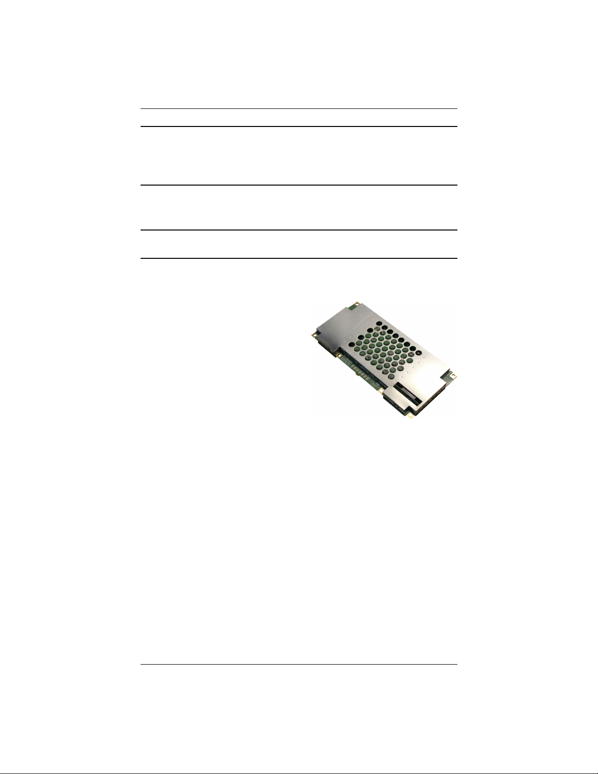
You can use the H321 for any application
needing accurate heading or DGPS or RTK
positioning. Fitted with Hemisphere GNSS’
patented Eclipse receiver technology, the
H321 computes heading and position using
two antennas. This design provides precise
heading and GPS sub-meter positioning
accuracy while stationary. And with
integrated SBAS support, you can receive
precision guidance anywhere those services
are available.
The H321 provides accurate, reliable
heading and position information at high
update rates. It does this by using a high performance GNSS engine for signal
processing.
The one receiver processes information from both the primary GPS antenna and
secondary GPS antenna. Positions computed by the H321 are referenced to the phase
center of the primary GPS antenna. Heading data references the vector formed from
the primary GPS antenna phase center to the secondary GPS antenna phase center.
What’s Included
The H321 is available in two configurations:
• H321 OEM board only - designed for integrators who are familiar with H321
board integration
• H321 OEM board and Universal Development Kit - designed for integrators
who are new to H321 board integration
The Universal Development Kit is designed to work with various
Hemisphere GNSS OEM boards and includes an enclosure with carrier
board, adapter boards, and various cables.
Eclipse Vector H321 Integrators Guide 2 PN 875-0345-0 Rev A1
Page 8

Chapter 1: Introduction
For more information on the Universal Development Kit visit
www.hemispheregnss.com and navigate to the GNSS OEM Board Products
page or contact your local dealer.
Eclipse Vector H321 Integrators Guide 3 PN 875-0345-0 Rev A1
Page 9

Chapter 1: Introduction
H321 Integration
Successful integration of the H321 within a system requires electronics expertise that
includes:
• Power supply design
• Serial port level translation
• Reasonable radio frequency competency
• An understanding of electromagnetic compatibility
• Circuit design and layout
The Eclipse GPS engine is a low-level module intended for custom integration with
the following general integration requirements:
• Regulated power supply input (3.3 VDC ± 3%) and 490 mA continuous
current
• Low-level serial port (3.3 V CMOS) and USB port communications
• Radio frequency (RF) input to the engine from a GPS antenna is required to
be actively amplified (10 to 40 dB gain)
• GPS antenna is powered with a separate regulated voltage source up to
15 VDC maximum
• Antenna input impedance is 50 Ω
H321 Features
Features of the H321 include:
• GNSS engine (3 channels dedicated to SBAS tracking)
• 20 mm horizontal accuracy with RTK 95%
• Raw measurement output (via documented binary messages)
• Position and heading update rates of 20 Hz maximum
• Robust RTK with Hemisphere GNSS’ SureTrack® technology
• Long-range RTK baselines up to 50 km
• Fast reacquisition times
• 10 m heading baseline
• COAST™ technology that provides consistent performance with correction
data
• Quick times to first fix
• Four full-duplex serial ports
• Two USB ports (1 USB host and 1 USB device)
• 1 PPS timing output
• Event marker input
Note: For complete specifications of the H321 see Appendix C, “Technical
Specifications.”
Eclipse Vector H321 Integrators Guide 4 PN 875-0345-0 Rev A1
Page 10

Chapter 1: Introduction
Configuring the H321
The H321 has four communication ports: A, B, C, and D. Ports A, B, and C are fully
independent and can have different messages output at different rates. You can
configure each of these ports for external correction input or output binary message
information or RTCM corrections from an outside source. You can also configure the
output of ports A, B, or C through any of these ports. Configure the baud rates if
necessary; the default is 19200 for Ports A, B, and C.
Port D is reserved for RTCM differential corrections and may be used by the
Hemisphere GNSS SBX-4™ board.
Configure the supplementary sensors if necessary. The tilt sensor operates by default
and the gyro is disabled but it is recommended that all sensors be turned on once
installation is complete.
Configure for your mode of differential operation: SBAS, beacon, or external
corrections.
NMEA 0183 Message Interface
The H321 uses a NMEA 0183 interface, allowing you to easily make configuration
changes by sending text-type commands to the receiver. For more information on
NMEA 0183 commands and messages refer to the Hemisphere GNSS Technical
Reference (go to www.hemispheregnss.com/support and follow the links to
Resources, GPS Reference Guide).
Binary Message Interface
In addition to the NMEA 0183 interface, the H321 also supports a selection of binary
messages. There is a wider array of information available through the binary
messages, plus binary messages are inherently more efficient with data. If the
application has a requirement for raw measurement data, this information is available
only in a binary format. For more information on binary messages refer to the
Hemisphere GNSS Technical Reference (go to www.hemispheregnss.com/support
and follow the links to Resources, GPS Reference Guide).
Using PocketMax to Communicate with the
H321
Hemisphere GNSS’ PocketMax is a free utility that runs on your PDA or computer and
allows you to easily interface with the H321. PocketMax also allows you to:
• Select the internal SBAS or external beacon or RTCM correction sources, if
available, and monitor reception
• Configure GPS message output and port settings
• Configure and monitor Vector-related settings
• Record various types of data
• Monitor the H321’s status and function
Connect your computer or PDA to the H321 via the COM port and open PocketMax.
The menus and tabs within PocketMax allow you to control the H321’s settings and
Eclipse Vector H321 Integrators Guide 5 PN 875-0345-0 Rev A1
Page 11

Chapter 1: Introduction
monitor its status. PocketMax is available as a free download from the OEM Products
Support page of the Hemisphere GNSS website at www.hemispheregnss.com.
Eclipse Vector H321 Integrators Guide 6 PN 875-0345-0 Rev A1
Page 12

Chapter 2: Board Overview
Mechanical Layout
Connectors
Mounting Options
Header and Pinouts
Signals
Shielding
Receiver Mounting
Thermal Concerns
Eclipse Vector H321 Integrators Guide 7 PN 875-0345-0 Rev A1
Page 13
MCX JACK
RECEPTACLE
7.3 mm
(.29 in)
16.3 mm
(.64 in)
15.0 mm
(.59 in)
5.1 mm
(.20 in)
12.7 mm
(.50 in)
MCX JACK
RECEPTACLE
12.7 mm
(.50 in)
5.1 mm
(.20 in)
3.8 mm
(.15 in)
54.7 mm
(2.15 in)
152.4 mm
(6.00 in)
1.3 mm
(.05 in)
1.6 mm
(.06 in)
6.1 mm
(.24 in)
71.1 mm
(2.80 in)
40.6 mm
(1.60 in)
64.8 mm
(2.55 in)
40.6 mm
(1.60 in)
3.2 mm
(.13 in)
146.1 mm
(5.75 in)
3.2 mm
(.13 in)
64.8 mm
(2.55 in)
3.2 mm
(.13 in)
3.2 mm
(.13 in)
x 6
Chapter 2: Board Overview
Mechanical Layout
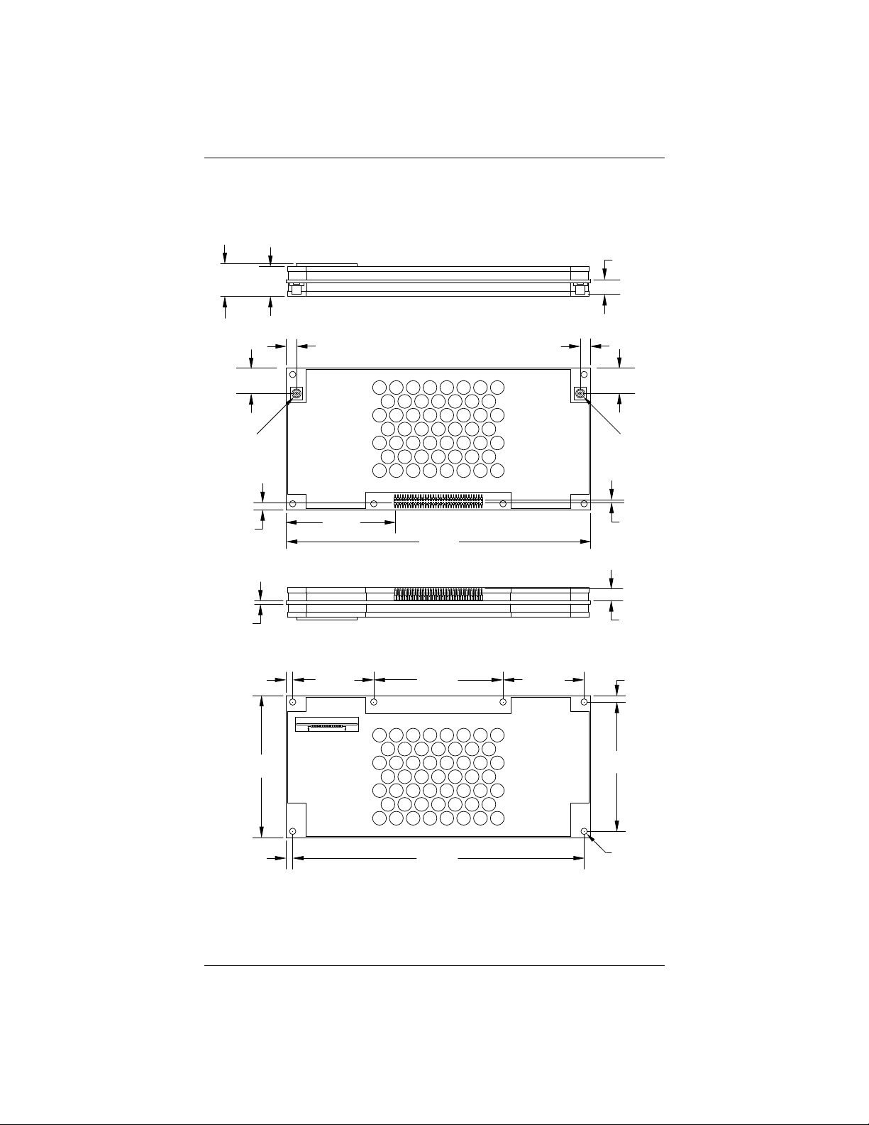
Figure 2-1 shows the mechanical layout for the H321. Dimensions are in millimeters
(inches).
Figure 2-1: H321 mechanical layout
Eclipse Vector H321 Integrators Guide 8 PN 875-0345-0 Rev A1
Page 14
Chapter 2: Board Overview
Connectors
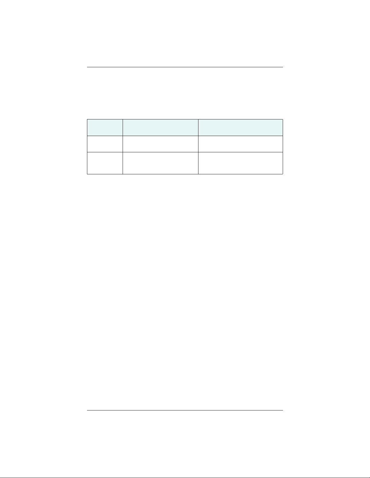
Table 2-1 describes the H321’s connectors and the mating connectors. You can use
different compatible connectors; however, the requirements may be different. The
antenna input impedance is 50 Ω.
Table 2-1: H321 connectors
Connector
Type
RF MCX, female straight jack
Power/data 70-pin (35x2) male header,
H321 SMT Connector Mating Connector
Johnson 133-3711-202
0.05 in (1.27 mm) pitch
Samtec FTSH-135-01-L-DV
MCX, male straight plug
Samtec RSP-127824-01
35x2 female SMT header socket,
0.05 in (1.27 mm) pitch
Samtec FLE-135-01-G-DV
Eclipse Vector H321 Integrators Guide 9 PN 875-0345-0 Rev A1
Page 15

Chapter 2: Board Overview
Mounting Options
There are two options for mounting the H321:
• Direct Electrical Connection method
• Indirect Electrical Connection (Cable) method
Direct Electrical Connection Method
Place an RF connector, heading connector, and mounting holes on the carrier board
and then mount the H321 on the standoffs and RF and header connectors. This
method is very cost effective as it does not use cable assemblies to interface the H321.
Note: Be aware of the GPS RF signals present on the carrier board and ensure the
correct standoff height to avoid any flexual stresses on the board when you fasten it
down.
The H321 uses a standoff height of 7.9 mm (0.3125 in). With this height there should
be no washers between either the standoff and the H321 or the standoff and the
carrier board; otherwise, you must make accommodations. You may need to change
the standoff height if you select a different header connector.
If you want to use a right angle MCX connector, use a taller header than the Samtec
part number suggested in this guide. This will provide clearance to have a right angle
cable-mount connector and reduce the complexity by not having the carrier board
handle the RF signals. See Table 2-1 on page 9 for H321 connector information.
The mounting holes of the H321 have a standard inner diameter of 3.2 mm (0.125 in).
Indirect Electrical Connection (Cable) Method
The second method is to mount the H321 mechanically so you can connect a ribbon
power/data cable to the H321. This requires cable assemblies and there is a reliability
factor present with cable assemblies in addition to increased expense.
Eclipse Vector H321 Integrators Guide 10 PN 875-0345-0 Rev A1
Page 16
Chapter 2: Board Overview
Header and Pinouts
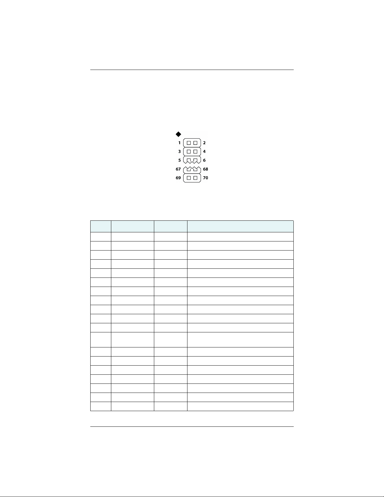
The H321 uses a dual-row header connector to interface with power, communications,
and other signals.
To identify the first header pin orient the board so the diamond is to the upper left of
the pins; the first pin is on the left directly below the diamond (see Figure 2-2). The
pins are then sequentially numbered per row from top to bottom.
Figure 2-2: H321 header layout
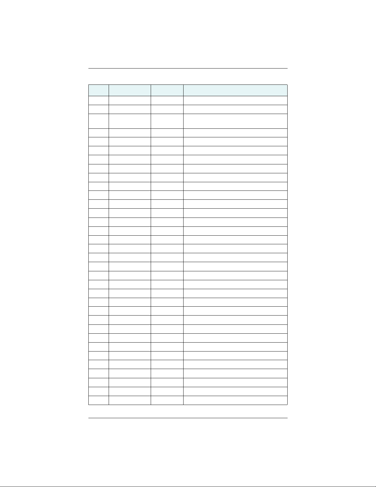
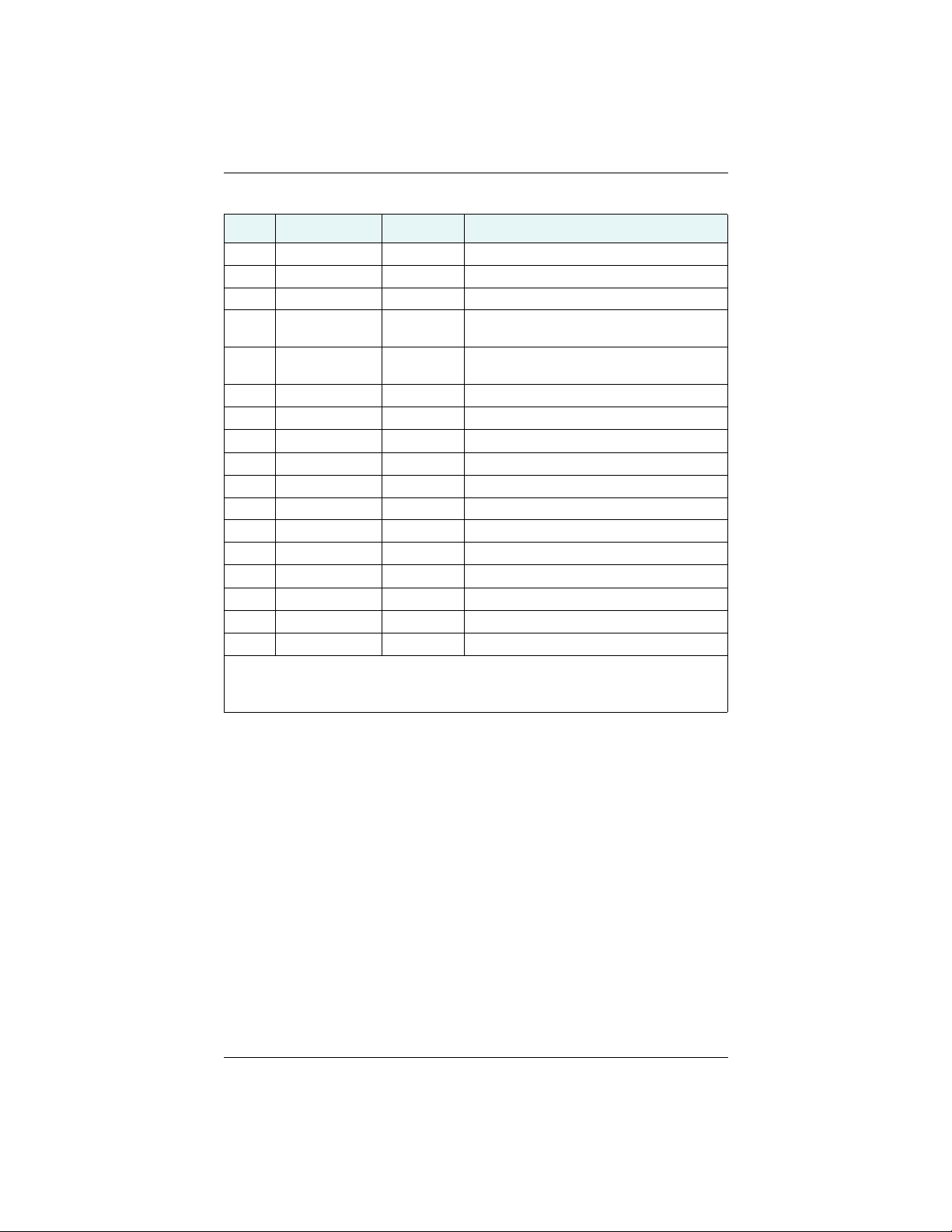
Table 2-2 provides pinout details for the H321 header.
Table 2-2: H321 header pinout descriptions
Pin Name Type Description
1 3.3 V Power Receiver power supply, 3.3 V
2 3.3 V Power Receiver power supply, 3.3 V
3 3.3 V Power Receiver power supply, 3.3 V
4 3.3 V Power Receiver power supply, 3.3 V
5 GND Power Receiver ground
6 GND Power Receiver ground
7 Antenna Pwr Power Antenna power, DC, 15 V max
8 Batt Backup Power Power, 2.7 to 4.5 V, 500 nA typical
9 n/c n/c n/c
10 n/c n/c n/c
11 n/c n/c n/c
12 Reset Open
collector
13 GND Power Receiver ground
14 GND Power Receiver ground
15 n/c n/c n/c
16 USB-DVBS Input Device USB bus power monitor
17 Manual Mark Input Active low, falling edge, 3.3 V CMOS
18 1 PPS Output Active low, falling edge, 3.3 V CMOS
19 Speed Output Output 0 - 3 V variable clock output
Reset, open collector, 3.3 V typical, not
required
Eclipse Vector H321 Integrators Guide 11 PN 875-0345-0 Rev A1
Page 17
Chapter 2: Board Overview
Table 2-2: H321 header pinout descriptions (continued)
Pin Name Type Description
20 Speed Ready Output Active low, speed valid indicator, 3.3 V CMOS
21 n/c n/c n/c
22 USB-PSW
Input Reserved for possible future USB OTG
(reserved)
23 GND Power Receiver ground
24 USB-HVBS Input Host USB bus power monitor
25 PATX Output Port A serial output, 3.3 V CMOS, idle high
26 PARX Input Port A serial input, 3.3 V CMOS, idle high
27 PBTX Output Port B serial output, 3.3 V CMOS, idle high
28 PBRX Input Port B serial input, 3.3 V CMOS, idle high
29 PCTX Output Port C serial output, 3.3 V CMOS, idle high
30 PCRX Input Port C serial input, 3.3 V CMOS, idle high
31 PDTX Output Port D serial output, 3.3 V CMOS, idle high
32 PDRX Input Port D serial input, 3.3 V CMOS, idle high
33 n/c n/c n/c
34 n/c n/c n/c
35 GND Power Receiver ground
36 GND Power Receiver ground
37 USB HOST+ I/O USB host data +
38 USB DEV+ I/O USB device data +
39 USB HOST– I/O USB host data -
40 USB DEV– I/O USB device data -
41 GND Power Receiver ground
42 n/c n/c n/c
43 n/c n/c n/c
44 n/c n/c n/c
45 n/c n/c n/c
46 GND Power Receiver ground
47 n/c n/c n/c
48 CANRX Input CAN, 3.3 V CMOS, receive
49 n/c n/c n/c
50 CANTX Output CAN, 3.3 V CMOS, transmit
51 GND Power Receiver ground
52 n/c n/c n/c
53 n/c n/c n/c
Eclipse Vector H321 Integrators Guide 12 PN 875-0345-0 Rev A1
Page 18
Chapter 2: Board Overview
Table 2-2: H321 header pinout descriptions (continued)
Pin Name Type Description
54 n/c n/c n/c
55 n/c n/c n/c
56 n/c n/c n/c
57 Primary GPS
Output Status indicator, 3.3 V CMOS, active low
Lock
58 Secondary GPS
Output Status indicator, 3.3 V CMOS, active low
Lock
59 Diff Lock Output Status indicator, 3.3 V CMOS, active low
60 n/c n/c n/c
61 DGPS Lock Output Status indicator, 3.3 V CMOS, active low
62 Heading Lock Output Status indicator, 3.3 V CMOS, active low
63 GND Power Receiver ground
64 GND Power Receiver ground
65 Analog GND Power Receiver ground
66 n/c n/c n/c
67 n/c n/c n/c
68 Analog GND Power Receiver ground
69 Analog GND Power Receiver ground
70 n/c n/c n/c
Note: • Pins are not 5 V tolerant. The pin voltage range is 0 to 3.3 VDC, unless
otherwise noted.
• Leave any data or I/O pins that will not be used unconnected.
Eclipse Vector H321 Integrators Guide 13 PN 875-0345-0 Rev A1
Page 19

Chapter 2: Board Overview
Signals
This section provides information on the signals available via connectors.
RF Input
The H321 is designed to work with active GPS antennas with an LNA gain range of 10
to 40 dB. The purpose of the range is to accommodate for losses in the cable system.
Essentially, there is a maximum cable loss budget of 30 dB for a 40 dB gain antenna.
Depending on the chosen antenna, the loss budget will likely be lower (a 24 dB gain
antenna would have a 14 dB loss budget).
When designing the internal and external cable assemblies and choosing the RF
connectors, do not exceed the loss budget; otherwise, you will compromise the
tracking performance of the H321.
Serial Ports
The H321 has four serial communication ports:
• Port A, Port B, Port C - main ports
• Port D - Exclusively used to interface with Hemisphere GNSS’ SBX-4 beacon
board or an external corrections source. This port will not output normal
GPS-related NMEA messages. When communicating into either Port A, B, or
C, a virtual connection may be established to the device on Port D using the
$JCONN command. See “Communication Port D” below for more
information on Port D.
The H321 serial ports’ 3.3 V CMOS signal level can be translated to interface with
other devices. For example, if serial Ports A, B, and/or C are used to communicate to
external devices such as PCs, you must translate the signal level from 3.3 V CMOS to
RS-232.
Communication Port D
Port D is exclusively for external DGPS correction input to the H321, such as from
Hemisphere GNSS’ SBX-4 beacon board.
USB Ports
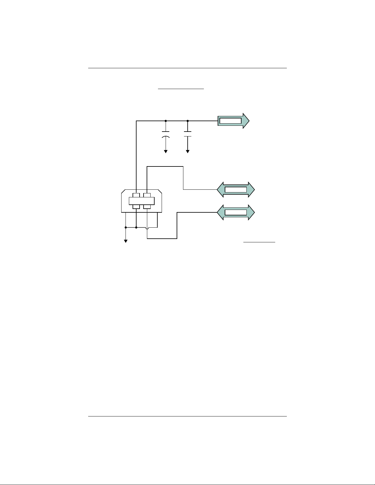
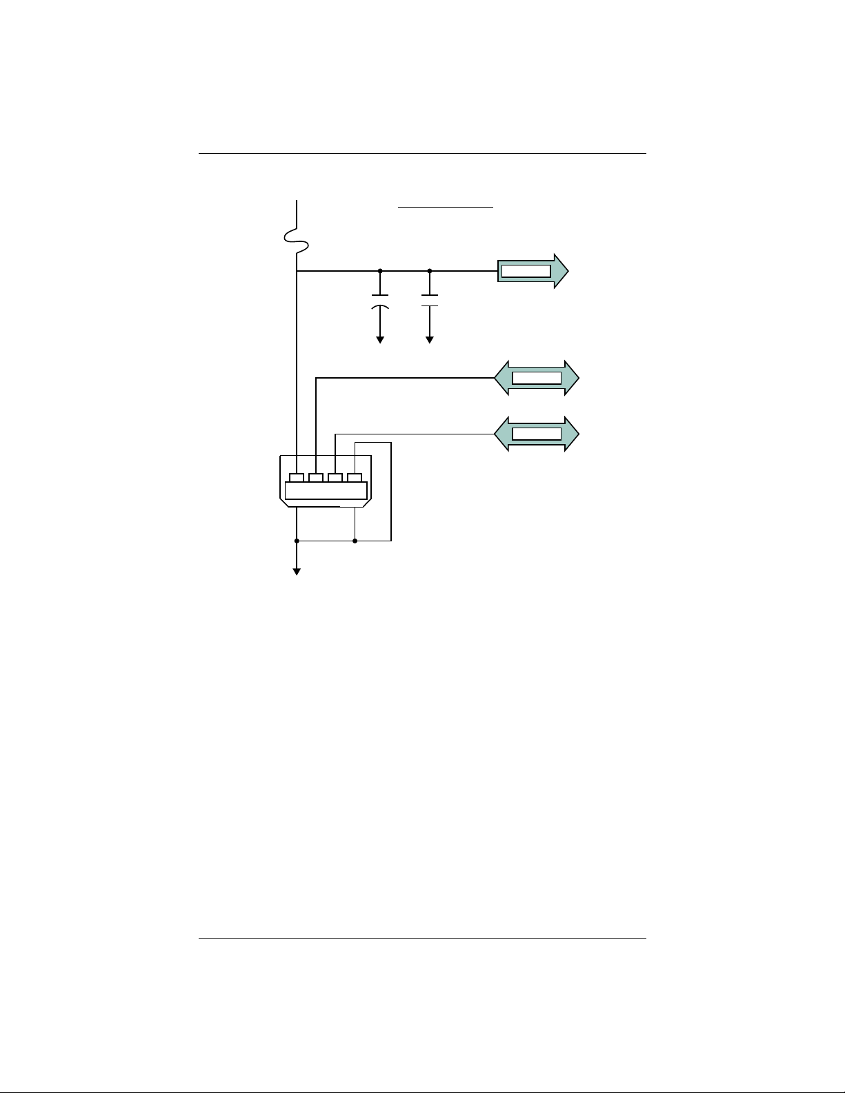
The H321 has one USB device port and one USB host port, where:
• USB Device port (data communication) shown in Figure 2-3 on page 15
serves as a high speed data communications port, such as for a PC
• USB Host port (data storage) shown in Figure 2-4 on page 16 serves as a
data storage port, such as with a USB flash drive
The USB data lines are bi-directional and are differential pairs. The USB data lines
should be laid out on printed wire board (PWB) with 90 Ω ±15% differential
impedance. The traces should be over a solid continuous ground plane. Maintain
parallel traces and symmetry. There shall be no traces or breaks in the ground plane
underneath the D+ and D- traces. It is also recommended to leave a minimum 20 mil
spacing between USB signals and other signals. Treat the data lines as if they are RF
signals.
Eclipse Vector H321 Integrators Guide 14 PN 875-0345-0 Rev A1
Page 20
Chapter 2: Board Overview
USB-DVBS
GND GND
USB– DEV
USB+ DEV
USB-B
GND
10µF 100nF
1
2
6
4
3
5
USB-DVBS
USB– DEV
USB+ DEV
Relevant Device H321 Pins
USB Device Power Detect
USB Device +
USB Device –
USB–DVBS
USB+ Host
USB– Host
User’s board shall have
1 µF to 10 µF capacitor
with ESR < 1Ω at the
USB device connector.
Device can use USB Type-B or
Mini-B connectors. If Mini-B
is used, “ID” pin 4 is NOT CONNECTED.
Normally, a device uses 5 V; however,
since H321 uses more than 500 mA
(2.5 W) it cannot use the BUS-supplied
5 V and therefore it is only monitored.
Figure 2-3: H321 USB device design example
Eclipse Vector H321 Integrators Guide 15 PN 875-0345-0 Rev A1
Page 21
Chapter 2: Board Overview
USB-HVBS
GND GND
USB– HOST
USB+ HOST
GND
120µF 100nF
1
2
5
6
3
USB-A
FUSE
5.0 V
4
USB-HVBS
USB– HOST
USB+ HOST
Relevant Host H321 Pins
USB Host Power Detect
USB Host +
USB Host –
USB–HVBS
USB+ Host
USB– Host
User’s board shall have
120 µF minimum capacitor
with ESR < 1Ω at the
USB host connector.
Host shall use USB Type-A connector.
If Mini-A is used, “ID” pin 4 is tied to GROUND.
Mini-A connectors are not widely used and this
Host port shall provide up to 500 mA (2.5 W)
of power at all times.
defeats the purpose and usability of USB drives
and typical accessories.
Figure 2-4: H321 USB host design example
Eclipse Vector H321 Integrators Guide 16 PN 875-0345-0 Rev A1
Page 22
Chapter 2: Board Overview
LED Indicators
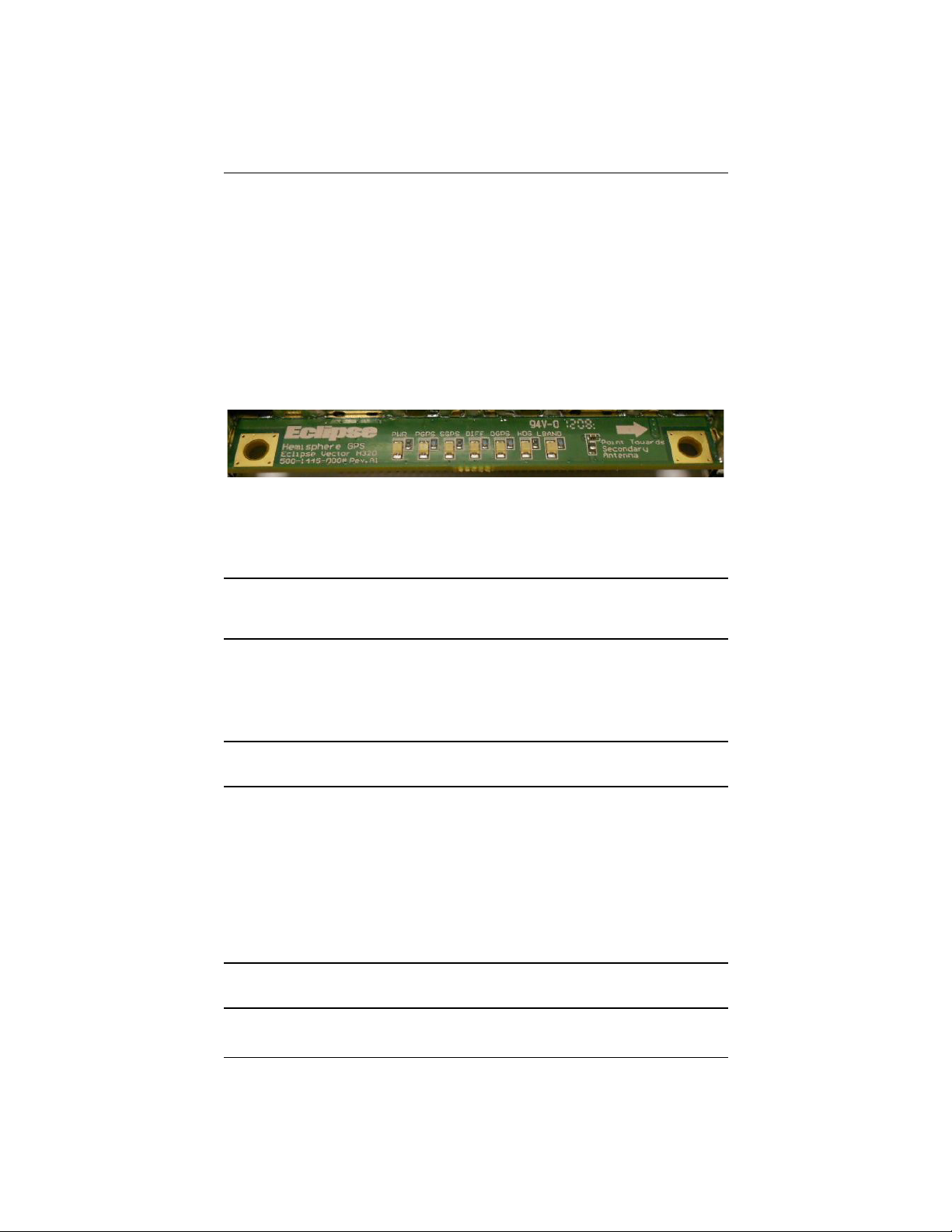
The H321 features the following surface-mounted diagnostic LEDs that indicate board
status (see Figure 2-5):
• PWR - Power
• PGPS - Primary GPS lock
• SGPS - Secondary GPS lock
• DIFF - Differential lock
• DGPS - DGPS position
• HDG - Heading lock
• L-BAND - L-band lock
Figure 2-5: Onboard LEDs
With the exception of the power LED the signals that drive the LEDs are available via
the header connector. Refer to Table 2-2 on page 11 for pin number descriptions for
the H321.
Note: Each signal pin can offer only 1 mA of current and is active low. Since 1 mA of
current may be inadequate for the application, you may want to transistor-buffer these
signals to provide more current capacity for acceptable LED luminance.
1PPS Timing Signal
The one pulse per second (1 PPS) timing signal is used in applications where devices
require time synchronization.
Note: 1 PPS is typical of most GPS boards but not essential to normal receiver
operation. Do not connect this pin if you do not need this function.
The 1 PPS signal is 3.3 V CMOS, active low with falling edge synchronization. The
1 PPS signal is capable of driving a load impendance greater than 10 kΩ in parallel
with 10 pF. The pulse is approximately 1 ms.
Event Marker Input
A GPS solution may need to be forced at a particular instance, not synchronized with
GPS time depending on the application, such as indicating to the GPS receiver when a
photo is taken from a camera used for aerial photography.
Note: Event marker input is typical of most GPS boards but not essential to normal
receiver operation. Do not connect this pin if you do not need this function.
Eclipse Vector H321 Integrators Guide 17 PN 875-0345-0 Rev A1
Page 23

Chapter 2: Board Overview
The event marker input is 3.3 V CMOS, active low with falling edge synchronization.
The input impedance and capacitance is higher than 10 kΩ and 10 pF, respectively,
with a threshold of lower than 0.7 V required to recognize the input.
Grounds
You must connect all grounds together when connecting the ground pins of the H321.
These are not separate analog and digital grounds that require separate attention.
Refer to Table 2-2 on page 11 for pinout ground information for the H321.
Speed Radar Output
Note: Speed radar output is not essential to normal receiver operation. Do not
connect these pins if you do not need this function.
The following two pins on the H321 relate to the Speed Radar.
• Speed Radar Pulse (pin 19) - Outputs a square wave with 50% duty cycle. The
frequency of the square wave varies directly with speed. 97 Hz represents a
speed of 1 m/s (3.28 ft/s).
• Speed Radar Ready Signal (pin 20) - Indicates when the speed signal on the
‘Speed Radar Pulse’ pin is valid. In static situations, such as when the vehicle
has stopped, the GPS position may still have slight variations from one
moment to the next. During these instances, the signal on the ‘Speed Radar
Ready Signal’ pin is ‘high’ or +Vcc, indicating the speed coming out of the
‘Speed Radar Pulse’ pin is erroneous and not truly indicative of the GPS
receiver’s actual speed. Therefore, it should not be referred to or be
used. Once the vehicle starts moving again and meets a minimum threshold
speed, the output on the ‘Speed Radar Ready Signal’ pin will go ‘low’
indicating valid speed information is present on the ‘Speed Radar Pulse’ pin.
Note: Neither pin 19 nor 20 has any form of isolation or surge protection. If utilizing
the Speed Radar Pulse output, Hemisphere GNSS strongly recommends
incorporating some form of isolation circuitry into the supporting hardware. Contact
Hemisphere GNSS Technical Support for an example of an optically isolated circuit.
Eclipse Vector H321 Integrators Guide 18 PN 875-0345-0 Rev A1
Page 24

Chapter 2: Board Overview
Shielding
The H321 is a sensitive instrument. When integrated into an enclosure, the H321
requires shielding from other electronics to ensure optimal operation. The H321 shield
design consists of a thin piece of metal with specific diameter holes, preventing
harmful interference from penetrating, while still allowing air circulation for cooling.
Receiver Mounting
The H321 is a precision instrument. To ensure optimal operation, consider mounting
the receiver in a way to minimize vibration and shock.
When mounting the H321 immediately adjacent to the GPS antenna, Hemisphere
GNSS highly recommends shielding the board from the LNA of the antenna. This step
can be more complex than some integrators initially estimate. Attempt to confirm the
operation in your application as early in the project as possible.
Thermal Concerns
The H321 receiver consumes a few watts of power, which ultimately will generate
heat. Since this may raise the ambient temperature inside an enclosure consider
managing the heat inside the enclosure to ensure the internal temperature does not
exceed the maximum operating temperature for the H321. Some suggestions for heat
management are heat sinks, heat conductive foam, or using a small cooling fan
possibly using a thermal switch. Air moving over the H321 removes heat very
effectively.
Note: Thermal design may only be a concern if the integrated product’s maximum
design temperature is expected to be close to that of the H321.
Eclipse Vector H321 Integrators Guide 19 PN 875-0345-0 Rev A1
Page 25

Page 26

Chapter 3: Operation
Powering the H321
Communicating with the H321
Configuring the H321
Firmware
Configuring the Data Message Output
Saving the H321 Configuration
Using Port D for RTCM Input
Configuration Defaults
Eclipse Vector H321 Integrators Guide 21 PN 875-0345-0 Rev A1
Page 27

Chapter 3: Operation
This chapter provides H321 operation information, such as communicating with the
H321, firmware, and configuration defaults.
Note: Install your antenna outdoors so it has a clear view of the entire sky. If you
place the antenna indoors near a window, for example, you will likely not track a
sufficient number of satellites. With a properly installed antenna the H321 provides a
position within approximately 60 sec.
Powering the H321
The H321 is powered by a 3.3 VDC power source. Once you connect appropriate
power the H321 is active. Although the H321 proceeds through an internal startup
sequence upon application of power, it is ready to communicate immediately.
Communicating with the H321
The H321 features three primary serial ports (Port A, Port B, Port C) that you can
configure independently from each other. You can configure the ports for any
combination of NMEA 0183, binary, and RTCM SC-104 data. The usual data output is
limited to NMEA data messages as these are industry standard.
Note: You may use the three serial ports to separate the different data types and
output different rates. If the H321 is required to output different data types
simultaneously, ensure data logging and the processing software used can correctly
parse the different data from a single stream.
Configuring the H321
You can configure all aspects of H321 operation through any serial port using
proprietary commands. These commands are described in detail in the Hemisphere
GNSS Technical Reference (go to www.hemispheregnss.com/support and follow the
links to Resources, GPS Reference Guide).
You can configure the following:
• Select one of the two firmware applications
• Set communication port baud rates
• Select which messages to output on the serial ports and the update rate of
each message
• Set various receiver operating parameters
For a complete lists of commands and messages refer to the Hemisphere GNSS
Technical Reference.
To issue commands to the H321 you will need to connect it to a terminal program such
as HyperTerminal or either of Hemisphere GNSS’ software applications (SLXMon or
PocketMax). See “What is the best software tool to use to communicate with the H321
and configure it?” on page 30 for descriptions of HyperTerminal, SLXMon, and
PocketMax.
Eclipse Vector H321 Integrators Guide 22 PN 875-0345-0 Rev A1
Page 28

Chapter 3: Operation
Firmware
The software that runs the H321 is often referred to as firmware since it operates at a
low level. You can upgrade the firmware in the field through any serial port as new
versions become available.
You can have two firmware applications loaded on the receiver; however, you can
only operate one at a time.
The H321 currently ships with the rover RTK application and the base RTK/SBAS
application. Refer to the Hemisphere GNSS Technical Reference (go to
www.hemispheregnss.com/support and follow the links to Resources, GPS Reference
Guide) for information on the $JAPP command, which you use to change between the
two H321 applications.
Configuring the Data Message Output
The H321 features three primary bi-directional ports (Ports A, B and C) and a
differential-only port (Port D). You can configure messages for all ports by sending
proprietary commands to the H321 through any port. For a complete list of commands
and messages refer to the Hemisphere GNSS Technical Reference (go to
www.hemispheregnss.com/support and follow the links to Resources, GPS Reference
Guide).
‘THIS’ Port and the ‘OTHER’ Port
Both Port A and Port B use the phrases “THIS” and “OTHER” when referring to
themselves and each other in NMEA messages.
‘THIS’ port is the port you are currently connected to for inputting commands. To
output data through the same port (‘THIS’ port) you do not need to specify 'THIS' port.
For example, when using Port A to request the GPGGA data message be output at
5 Hz on the same port (Port A), issue the following command:
$JASC,GPGGA,5<CR><LF>
The ‘OTHER’ port is either Port A or Port B, whichever one you are not using to issue
commands. If you are using Port A to issue commands, then Port B is the ‘OTHER’
port, and vice versa. To specify the ‘OTHER’ port for the data output you need to
include 'OTHER' in the command. For example, if you use Port A to request the
GPGGA data message be output at 5 Hz on Port B, issue the following command:
$JASC,GPGGA,5,OTHER<CR><LF>
When using Port A or Port B to request message be output on Port C, you must
specifically indicate (by name) you want the output on Port C. For example, if you use
Port A to request the GPGLL data message be output at 10 Hz on Port C, issue the
following command:
$JASC,GPGLL,10,PORTC<CR><LF>
Eclipse Vector H321 Integrators Guide 23 PN 875-0345-0 Rev A1
Page 29

Chapter 3: Operation
Saving the H321 Configuration
Each time you change the H321’s configuration you may want to save it so you do not
have to reconfigure the receiver each time you power it on. To save the configuration,
issue the $JSAVE command to the Eclipse using a terminal program such as
HyperTerminal or either of Hemisphere GNSS’ applications (SLXMon or PocketMax).
The H321 will take approximately five seconds to save the configuration to nonvolatile memory and will indicate when the configuration has been saved. Refer to the
Hemisphere GNSS Technical Reference (go to www.hemispheregnss.com/support
and follow the links to Resources, GPS Reference Guide) for more information on the
$JSAVE command.
Using Port D for RTCM Input
Port D has been optimized to interface with Hemisphere GNSS’ SBX-4 beacon board
and operates at 960 0 baud (8 data bits, no parity and 1 stop bit – 8-N-1).
To configure the H321 to use Port D, issue the following command:
$JDIFF,BEACON<CR><LF>
To return to using SBAS as the correction source, send the following command to the
H321:
$JDIFF,WAAS<CR><LF>
For a complete list of commands and messages refer to the Hemisphere GNSS
Technical Reference (go to www.hemispheregnss.com/support and follow the links to
Resources, GPS Reference Guide).
Eclipse Vector H321 Integrators Guide 24 PN 875-0345-0 Rev A1
Page 30

Chapter 3: Operation
Configuration Defaults
Below is the standard configuration for the H321. For more information on these
commands refer to the Hemisphere GNSS Technical Reference (go to
www.hemispheregnss.com/support and follow the links to Resources, GPS Reference
Guide).
$JOFF,PORTA
$JOFF,PORTB
$JOFF,PORTD
$JAGE,2700
$JLIMIT,10
$JMASK,5
$JNP,5
$JWAASPRN,AUTO
$JDIFF,WAAS
$JPOS,51.0,-114.0
$JSMOOTH,LONG
$JTAU,COG,0.00
$JTAU,SPEED,0.00
$JAIR,AUTO
$JALT,NEVER
$JATT,HTAU,0.1
$JATT,HRTAU,2.0
$JATT,COGTAU,0.0
$JATT,MSEP,1.0
$JATT,GYROAID,YES
$JATT,TILTAID,YES
$JATT,LEVEL,NO
$JATT,EXACT,NO
$JATT,HIGHMP,YES
$JATT,FLIPBRD,NO
$JATT,HBIAS,0.0
$JATT,NEGTILT,NO
$JATT,NMEAHE,0
$JATT,PBIAS,0.0
$JATT,PTAU,0.5
$JATT,ROLL,NO
$JATT,SPDTAU,0.0
$JBAUD,19200,PORTA
$JASC,GPGGA,1,PORTA
$JASC,GPHDT,10,PORTA
$JASC,GPROT,10,PORTA
$JASC,GPHPR,1,PORTA
$JBAUD,19200,PORTB
$JASC,GPGGA,1,PORTB
$JASC,GPHDT,10,PORTB
$JASC,GPROT,10,PORTB
$JASC,GPHPR,1,PORTB
$JSAVE
Eclipse Vector H321 Integrators Guide 25 PN 875-0345-0 Rev A1
Page 31

Page 32

Appendix A: Frequently Asked Questions
Integration
Power, Communication, and Configuration
GPS Reception and Performance
SBAS Reception and Performance
External Corrections
Installation
Support and Repair
Eclipse Vector H320 Integrators Guide 27 PN 875-0345-0 Rev A1
Page 33

Appendix A: Frequently Asked Questions
Integration
Do I need to use the 1 PPS and event marker?
No, these are not necessary for H321 operation.
What should I do with the 1 PPS signal if I do not want to use it?
This signal will be strobing at 1 Hz, so it should not be connected.
What should I do with the manual mark input if I am not going to use it?
Do not connect the pin because this signal is active low.
Do I need to use the lock indicators?
No, these are present for applications where it is desirable to have an LED visible to
the user. These signals need to be transistor-buffered, as these lines can only offer
1 mA. Depending on the product and the application, LEDs can be very useful to the
end user. These signals are active low.
Do I need to use a shield-can for the H321?
Not necessarily...but you may need to if there are RF interference issues, such as if the
H321 interferes with other devices. A shield-can would be a good start in terms of
investigating the benefit. If you are designing a smart antenna system, one is likely
needed. Hemisphere GNSS recommends that you always conduct an RF prescan
when integrating OEM boards.
If my company wishes to integrate this product, what type of engineering
resources will I need to do this successfully?
Hemisphere GNSS recommends you have sufficient engineering resources with the
appropriate skills in and understanding of the following:
• Electronic design (including power supplies and level translation)
• RF implications of working with GPS equipment
• Circuit design and layout
• Mechanical design and layout
What type of assistance can I expect from Hemisphere GNSS when
integrating the H321?
Integration of a GPS board has such benefits as:
• Lower system cost
• Improved branding (rather than relabeling an existing product)
• Better control of system design
As an integrator, you are responsible for ensuring that the correct resources are in
place to technically complete the integration. Hemisphere GNSS will provide
reasonable assistance; however, Hemisphere GNSS does not have dedicated
engineering resources for in-depth integration support. Hemisphere GNSS will do its
best to provide support as necessary, but you should expect to have reasonable
expertise to use this Integrators Guide.
Eclipse Vector H320 Integrators Guide 28 PN 875-0345-0 Rev A1
Page 34

Appendix A: Frequently Asked Questions
Power, Communication, and Configuration
My H321 system does not appear to be communicating. What do I do?
This could be one of a few issues:
• Examine the H321 cables and connectors for signs of damage or offset.
• Ensure the H321 system is properly powered with the correct voltage.
• Ensure there is a good connection to the power supply since it is required to
terminate the power input with the connector.
• Check the documentation of the receiving device, if not a PC, to ensure the
transmit line from the H321 is connected to the receive line of the other
device. Also, ensure the signal grounds are connected.
• If the H321 is connected to a custom or special device, ensure the serial
connection to it does not have any incompatible signal lines present that
prevent proper communication.
• Make sure the baud rate of the H321 matches the other device. The other
device must also support an 8 data bit, 1 stop bit, no parity port
configuration (8-N-1). Some devices support different settings that may be
user configurable. Ensure the settings match.
• Consult the troubleshooting section of the other device’s documentation to
determine if there may be a problem with the equipment.
Am I able to configure two serial ports with different baud rates?
Yes, all the ports are independent. For example, you may set one port to 4800 and
another port to 19200.
Am I able to have the H321 output different NMEA messages through
multiple ports?
Yes, different NMEA messages can be sent to the serial ports you choose. These
NMEA messages may also be at different update rates.
A high enough baud rate is needed to transmit all the data; otherwise, some data may
not be transmitted.
How can I determine the current configuration of the H321?
The $JSHOW command will request the configuration information from the H321. The
response will be similar to:
$>JSHOW,BAUD,19200
$>JSHOW,BIN,1,5.0
$>JSHOW,BAUD,4800,OTHER
$>JSHOW,ASC,GPGGA,1.0,OTHER
$>JSHOW,ASC,GPVTG,1.0,OTHER
$>JSHOW,ASC,GPGSA,1.0,OTHER
How can I be sure the configuration will be saved for the subsequent power
cycle?
Query the receiver to make sure the current configuration is correct by issuing a
$JSHOW command. If not, make the necessary changes and reissue the $JSHOW
command. Once the current configuration is acceptable, issue a $JSAVE command
and wait for the receiver to indicate the save is complete. Do not power off the
receiver until the “save complete” message appears.
Eclipse Vector H320 Integrators Guide 29 PN 875-0345-0 Rev A1
Page 35

Appendix A: Frequently Asked Questions
How do I change the baud rate of a port from that port?
Connect at the current baud rate of the H321 port and then issue a $JBAUD command
to change the port baud rate to the desired rate. Now change the baud rate in your
application to the desired rate.
What is the best software tool to use to communicate with the H321 and
configure it?
Hemisphere GNSS uses three different software applications:
• HyperTerminal™ - Available on all Windows® 95, 98, ME, and XP. This tool
allows you to configure the H321 by directly typing commands into the
terminal window. The output from the H321 is simultaneously shown. When
using HyperTerminal, ensure it is configured to use the correct PC
communication port and baud rate, and that the local echo feature is on (to
see what is being typed).
• SLXMon - Available at www.hemispheregnss.com. This application is a very
useful tool for graphically viewing tracking performance and position
accuracy, and for recording data. It can also configure message output and
port settings. SLXMon runs on Windows 95 or higher.
• PocketMax - Available at www.hemispheregnss.com. Similar to SLXMon,
you can use this application to graphically view tracking performance and
position accuracy, record data, and configure message output and port
settings. PocketMax runs on multiple Windows platforms using the
Windows .NET framework.
GPS Reception and Performance
How do I know what the H321 is doing?
The H321 supports standard NMEA data messages. The $GPGSV and Bin99 data
messages contain satellite tracking and SNR information. If available, the computed
position is contained in the $GPGGA message. Additionally, the H321 has surfacemounted status LEDs that indicate receiver status.
Do I have to be careful when using the H321 to ensure it tracks properly?
For best performance, the H321’s antenna must have a clear view of the sky for
satellite tracking. The H321 can tolerate a certain amount of signal blockage because
redundant satellites are often available. Only four satellites are required for a position;
however, the more satellites that are used, the greater the positioning accuracy.
Eclipse Vector H320 Integrators Guide 30 PN 875-0345-0 Rev A1
Page 36

Appendix A: Frequently Asked Questions
SBAS Reception and Performance
How do I know if the H321 has acquired an SBAS signal?
The H321 outputs the $RD1 message that contains the SBAS bit error rate (BER) for
each SBAS channel. The BER value describes the rate of errors received from SBAS.
Ideally, this should be zero. However, the H321 performs well up to 150 BER. The
SLXMon and PocketMax utilities provide this information without needing to use
NMEA commands.
How do I know if the H321 is offering a differentially-corrected or
RTK-corrected position?
The H321 outputs the $GPGGA message as the main positioning data message. This
message contains a quality fix value that describes the GPS status. If this value is 2,
the position is differentially corrected; if this value is 5, the position is RTK-corrected.
The SLXMon and PocketMax utilities provide this information without needing to use
NMEA commands.
How do I select an SBAS satellite?
By default the H321 will automatically attempt to track the appropriate SBAS satellites.
If multiple satellites are available, the one with the lowest BER value is selected to be
used to decode the corrections.
You can manually select which SBAS satellites to track (refer to the Hemisphere GNSS
Technical Reference—go to www.hemispheregnss.com/support and follow the links to
Resources, GPS Reference Guide—for more information); however, this is not
recommended.
Should I be concerned if the H321 is frequently losing lock on SBAS due to
obstructions or low satellite elevation angles at my geographic location?
No, provided that the receiver is receiving a full set of corrections relatively often.
Using COAST technology, the H321 is able to perform well for 40 minutes or more
with aging correction data. Similar to DGPS corrections, accuracy degrades over time
and distance. To obtain a full set of corrections the H321 antenna receives the
ionospheric map over a period of a few minutes. This is the minimum amount of time
required to get a full set of corrections for SBAS operation. After this, the receiver can
coast until the next set of corrections have been received.
Accuracy is a function of correction age and current ionospheric activity, which will
increase in the coming years.
Do I need a dual frequency antenna for SBAS?
Hemisphere GNSS recommends using a dual frequency antenna with the H321. While
some receiver function is possible with an L1-only antenna, full receiver performance
will only be realized with a dual frequency antenna.
Eclipse Vector H320 Integrators Guide 31 PN 875-0345-0 Rev A1
Page 37

Appendix A: Frequently Asked Questions
External Corrections
My H321 system does not appear to be using DGPS or RTK corrections from
an external correction source. What could be the problem?
This could be due to a number of factors. To isolate the issue:
• Make sure DGPS corrections are RTCM v2.3 protocol.
• Make sure RTK corrections are either ROX, RTCM v3, CMR, or CMR+
protocol.
• Verify the baud rates used by the H321 match that of the external correction
source.
• The external correction should be using an 8 data bit, no parity, 1 stop bit
(8-N-1) serial port configuration.
• Inspect the cable connection to ensure there is no damage.
• Check the pinout information for the cables to ensure the transmit line of the
external correction source is connected to the receive line of the H321 serial
port and that the signal grounds are connected.
• Make sure the H321 has been set to receive external corrections by issuing
the $JDIFF command. Refer to the Hemisphere GNSS Technical Reference
(go to www.hemispheregnss.com/support and follow the links to Resources,
GPS Reference Guide) for more information.
Installation
Does it matter where I mount the H321’s antenna?
Yes, the mounting location must provide a clear view of the sky for satellite tracking.
Additionally, the position that it computes is based on the center of the antenna. It
should be placed in the location for which the user would like a position. Often
antennas are mounted on the centerline of a vehicle or on a pole-mount for
georeference.
How will the antenna selection and mounting affect H321 performance?
For best results select a multipath-resistant antenna. Ensure the antenna tracks all the
available signals for the receiver.
Mount the antenna:
• With the best possible view of the sky
• In a location with the lowest possible multipath
Using a magnetic mount for the antenna will not affect performance.
Eclipse Vector H320 Integrators Guide 32 PN 875-0345-0 Rev A1
Page 38

Appendix A: Frequently Asked Questions
Support and Repair
How do I solve a problem I cannot isolate?
Hemisphere GNSS recommends contacting the dealer first. With their experience with
this product, and other products from Hemisphere GNSS, they should be able to help
isolate a problem. If the issue is beyond the capability or experience of the dealer,
Hemisphere GNSS Technical Support is available from 8:00 AM to 5:00 PM Mountain
Standard Time, Monday through Friday.
See “Technical Support” on page i (just before the Contents page) for Technical
Support contact information.
What do I do if I cannot resolve a problem after trying to diagnose it myself?
Contact your dealer to see if they have any information that may help to solve the
problem. They may be able to provide some in-person assistance. If this is not viable
or does not solve the problem, Hemisphere GNSS Technical Support is available from
8:00 AM to 5:00 PM Mountain Standard Time, Monday through Friday.
See “Technical Support” on page i (just before the Contents page) for Technical
Support contact information.
Can I contact Hemisphere GNSS Technical Support directly regarding
technical problems?
Yes, however, Hemisphere GNSS recommends speaking to the dealer first as they
would be the local support. They may be able to solve the problem quickly, due to
their closer location and experience with our equipment.
Eclipse Vector H320 Integrators Guide 33 PN 875-0345-0 Rev A1
Page 39

Page 40

Appendix B: Troubleshooting
Eclipse Vector H321 Integrators Guide 35 PN 875-0345-0 Rev A1
Page 41

Appendix B: Troubleshooting
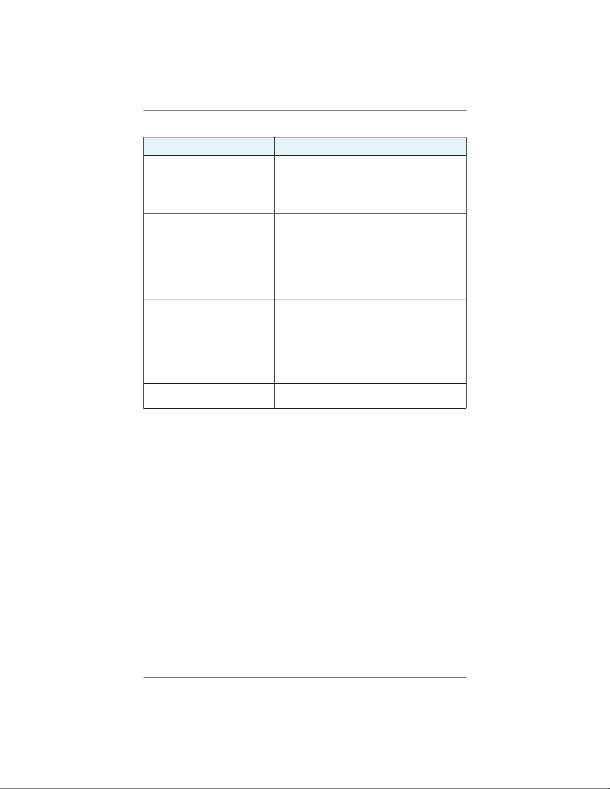
Table B-1 provides a list of issues with possible solutions to help you troubleshoot
anomalous H321 operation. Refer to Appendix C, “Technical Specifications” if
necessary.
Table B-1: Troubleshooting
Issue Possible Solution
What do I do initially if I have a
problem with the operation of the
H321?
Receiver fails to power • Verify polarity of power leads
No data from the H321
1. No communication
2. No valid data
Random binary data from the H321
Try to isolate the source of the problem. Problems
are likely to fall within one of the following
categories:
• Power, communication, and configuration
• GPS reception and performance
• Beacon reception and performance
• SBAS reception and performance
• External corrections
• Installation
• Shielding and isolating interference
It is important to review each category in detail to
eliminate it as a problem.
• Check 1.0 A in-line power cable fuse connection
• Check integrity of power cable connections
• Check power input voltage
• Check current restrictions imposed by power
source (minimum available should be > 1.0 A)
• (1) Check receiver power status (this may be
done with an ammeter)
• (2) Verify the H321 is locked to a valid DGPS
signal (this can often be done on the receiving
device or by using SLXMon)
• (2) Verify the H321 is locked to GPS satellites
(this can often be done on the receiving device
or by using SLXMon)
• (2) Check integrity and connectivity of power
and data cable connections
• Verify the RCTM or Bin messages are not being
accidentally output (send a $JSHOW command)
• Verify the baud rate settings of H321 and remote
device match
• Potentially, the volume of data requested to be
output by the Eclipse could be higher than the
current baud rate supports. Try using 19200 or
higher for the baud rate for all devices
Eclipse Vector H321 Integrators Guide 36 PN 875-0345-0 Rev A1
Page 42
Appendix B: Troubleshooting
Table B-1: Troubleshooting
Issue Possible Solution
No GPS lock • Check integrity of antenna cable
• Verify antenna’s view of the sky
• Verify the lock status and signal to noise ratio
(SNR) of GPS satellites (this can often be done
on the receiving device or by using SLXMon)
No SBAS • Check integrity of antenna cable
• Verify antenna’s view of the sky, especially
toward SBAS satellites, south in the northern
hemisphere
• Verify the bit error rate and lock status of SBAS
satellites (this can often be done on the
receiving device or by using SLXMon - monitor
BER value)
No DGPS position in external
RTCM mode
• Verify the baud rate (BER) of the RTCM input
port matches the baud rate of the external
source
• Verify the pinout between the RTCM source and
the RTCM input port (the ‘ground’ pin and
pinout must be connected, and the ‘transmit’
from the source must connect to the ‘receiver ’
of the RTCM input port).
Non-DGPS output
• Verify H321 SBAS and lock status (or external
source is locked)
Eclipse Vector H321 Integrators Guide 37 PN 875-0345-0 Rev A1
Page 43

Page 44

Appendix C: Technical Specifications
Eclipse Vector H321 Integrators Guide 39 PN 875-0345-0 Rev A1
Page 45
Appendix C: Technical Specifications
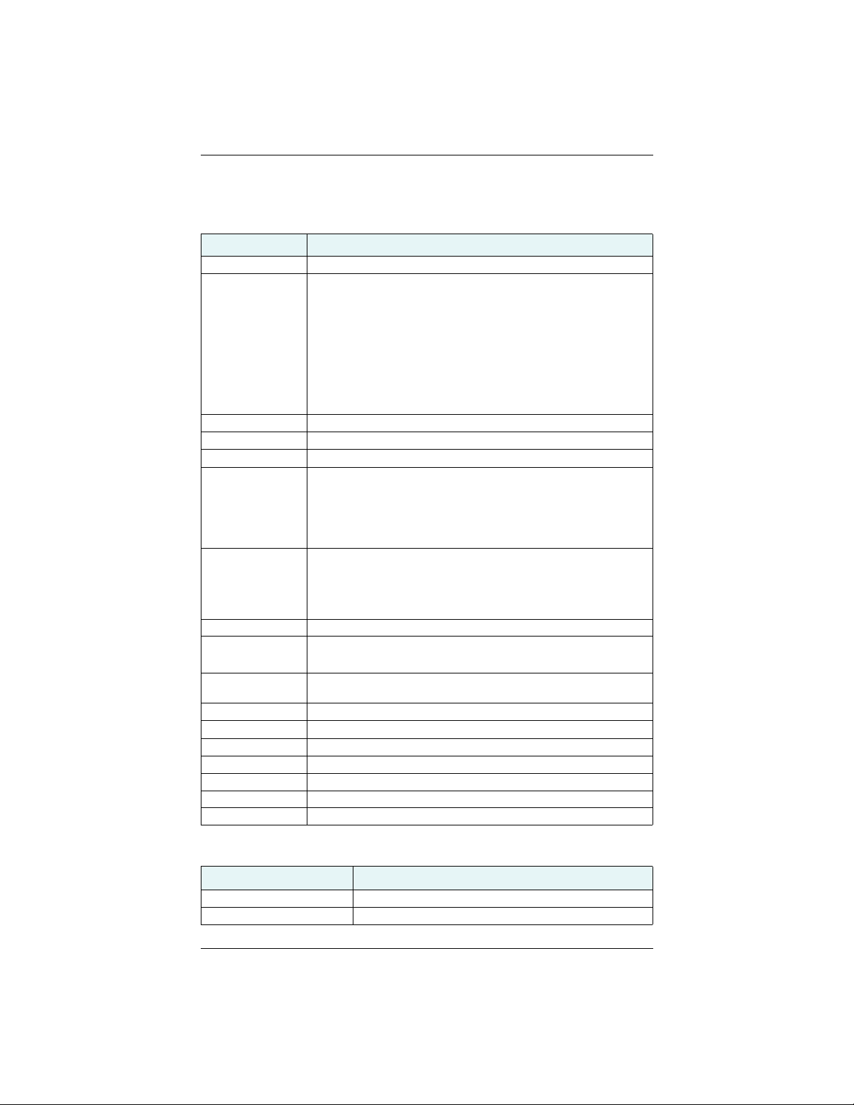
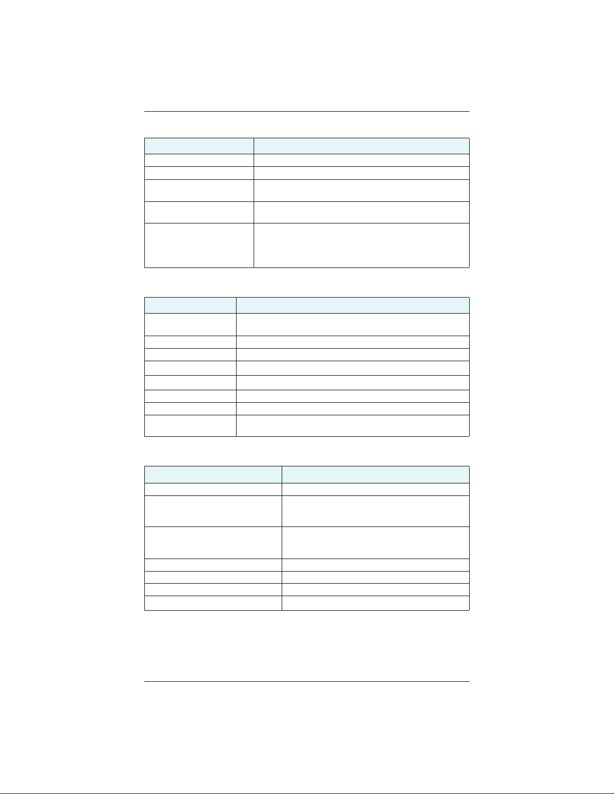
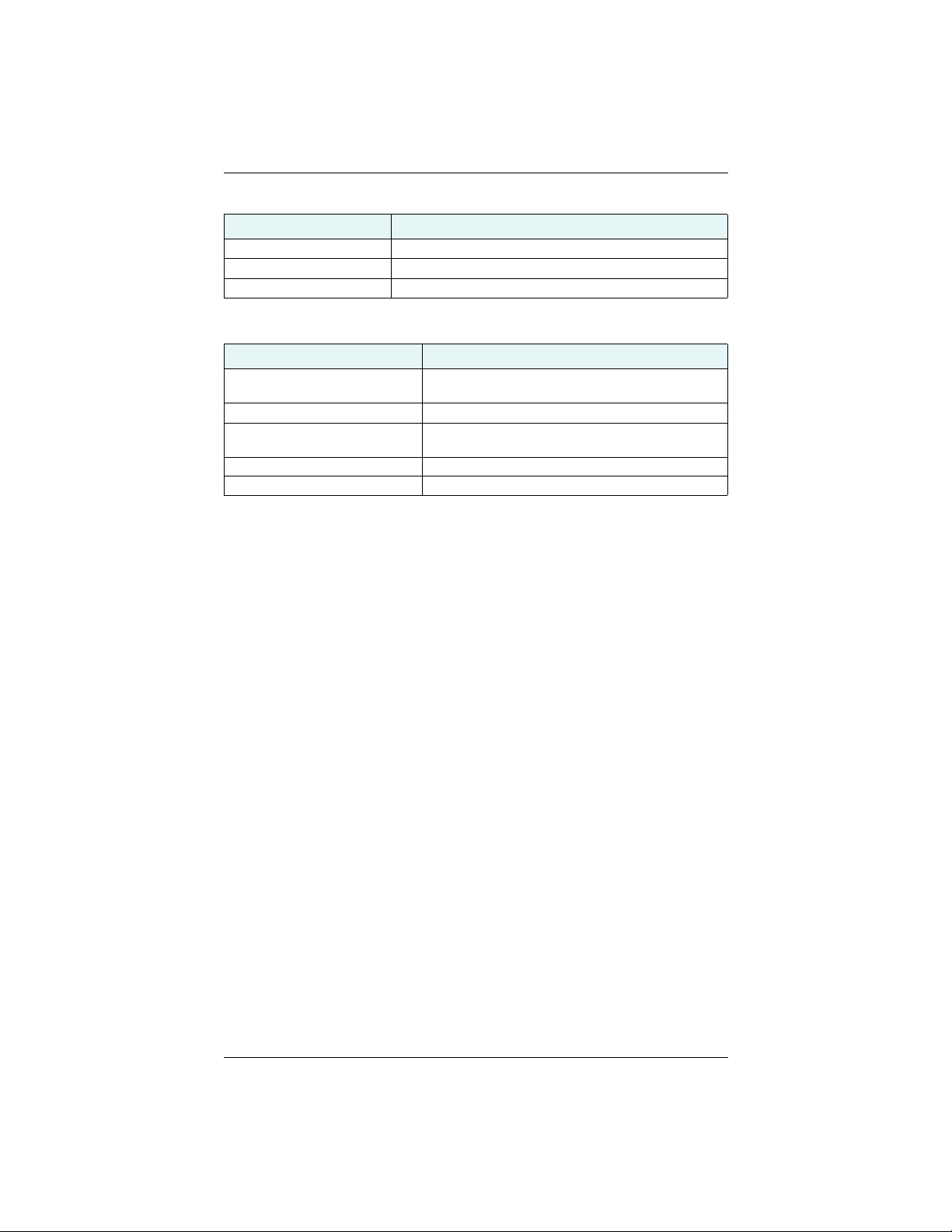
Table C-1 through Table C-6 provide GNSS sensor, L-band, communication, power,
environmental, and mechanical specifications of the H321.
Table C-1: GNSS sensor specifications
Item Specification
Receiver type Dual GNSS (GPS/GLONASS) RTK
Channels 12 L1CA GPS
12 L1P GPS
12 L2P GPS (with subscription code)
12 L2C GPS (with subscription code)
12 L1 GLONASS (with subscription code)
12 L2 GLONASS (with subscription code)
12 L1 BeiDou (with subscription code)
12 L2 BeiDou (with subscription code)
3 SBAS or 3 additional L1CA GPS
1 L-Band SBAS
GPS sensitivity -142 dBm
SBAS tracking 3-channel, parallel tracking
Update rate 10 Hz standard, 20 Hz available
Horizontal accuracy
1,2
RTK
L-band high precision services
SBAS (WAAS)
Autonomous, no SA
2
2
RMS (67%)
10 mm + 1 ppm
2,3
0.08 m
0.25 m
1.2 m
2DRMS (95%)
20 mm + 2 ppm
0.16 m
0.50 m
2.5 m
Heading accuracy < 0.17º rms @ 0.5 m antenna separation
< 0.09º rms @ 1.0 m antenna separation
< 0.04º rms @ 2.0 m antenna separation
< 0.02º rms @ 5.0 m antenna separation
< 0.01º rms @ 10.0 m antenna separation
Pitch/roll accuracy < 1º rms
Heave accuracy
30 cm rms (DGPS)
4
5 cm rms (RTK)4
Timing (1PPS)
20 ns
accuracy
Rate of turn 100º/s maximum
Cold start time < 60 s typical (no almanac or RTC)
Warm start time < 30 s typical (almanac, RTC, and position)
Hot start time < 10 s (ephemeris, RTC, and position)
Heading fix < 10 s typical (hot start)
Maximum speed 1,850 kph (999 kts)
Maximum altitude 18,288 m (60,000 ft)
Table C-2: L-band sensor specifications
Item Description
Sensitivity -130 dBm
Channel spacing 7.5 KHz
Eclipse Vector H321 Integrators Guide 40 PN 875-0345-0 Rev A1
Page 46
Appendix C: Technical Specifications
Table C-2: L-band sensor specifications (continued)
Item Description
Satellite selection Manual and Automatic
Reacquisition time 15 seconds (typical)
Rejection 15 kHz spacing > 30 dB
300 kHz spacing > 60 dB
Processor DSP for demodulation and protocol decoding module
provides processing for differential algorithms
Command support Reports L-band region and satellite information
Allows input and status of L-band subscription, bit error
rate (BER) output for reception quality indication and
manual frequency tuning.
Table C-3: Communication specifications
Item Description
Serial ports 4 full-duplex 3.3 V CMOS
(3 main serial ports, 1 differential-only port)
USB ports 1 USB host, 1 USB device
Baud rates 4800 - 115200
Data I/O protocol
NMEA 0183, Crescent binary
5
Correction I/O protocol RTCM SC-104, RTCM v2.3 (DGPS), RTCM v3 (RTK), CMR, CMR+
Timing output 1 PPS CMOS, active low, falling edge sync, 10 kΩ, 10 pF load
Event marker input CMOS, active low, falling edge sync, 10 kΩ, 10 pF load
Heading warning I/O
Pin 62 (see Table 2-2 on page 11 for more information)
(Heading Lock)
6
Table C-4: Power specifications
Item Specification
Input voltage 3.3 VDC +/- 5%
Power consumption < 3.8 W at 3.3 V (L1/L2 GPS/GLONASS/BeiDou)
< 4.8 W at 3.3 V (L1/L2 GPS/GLONASS/BeiDou; Lband)
Current consumption < 1160 mA at 3.3 V (L1/L2 GPS/GLONASS/BeiDou)
< 1465 mA at 3.3 V (L1/L2 GPS/GLONASS/BeiDou;
L-band)
Antenna voltage input 15 VDC maximum
Antenna short circuit protection Yes
Antenna gain input range 10 to 40 dB
Antenna input impedance
Eclipse Vector H321 Integrators Guide 41 PN 875-0345-0 Rev A1
50 Ω
Page 47
Appendix C: Technical Specifications
Table C-5: Environmental specifications
Item Specification
Operating temperature -40°C to +85°C (-40°F to +185°F)
Storage temperature -40°C to +85°C (-40°F to +185°F)
Humidity 95% non-condensing (when installed in an enclosure)
Table C-6: Mechanical specifications
Item Description
Dimensions 152.4 L x 71.1 W x 16.3 H mm
(6.00 L x 2.80 W x 0.64 H in)
Weight .105 kg (3.70 oz.)
Status indication (LED) Power, Primary and Secondary GPS lock, Differential
lock, DGPS position, Heading, RTK lock, L-band lock
Power/data connector 70-pin male header, 0.05” (1.27 mm) pitch
Antenna connector MCX, female, straight
1
Depends on multipath environment, number of satellites in view, satellite geometry,
baseline length (for local services), and ionospheric activity.
2
Depends on multipath environment, number of satellites in view, satellite geometry
and ionospheric activity.
3
Requires an L-band subscription.
4
Based on a 40-second time constant.
5
Hemisphere GNSS proprietary.
6
Receive only, does not transmit this format.
Eclipse Vector H321 Integrators Guide 42 PN 875-0345-0 Rev A1
Page 48

Index
Numerics
1 PPS timing signal 17
B
binary messages 5
board
connectors 9
header 11
integration 4
LED indicators 17
mechanical layout 8
mounting options 10
shielding 19
thermal concerns 19
USB device design example 15
USB host design example 16
board features 4
C
COAST technology 4
communication Port D 14
communication specifications 41
connectors 9
D
DGPS LED indicator 17
DGPS position LED indicator 17
DIFF LED indicator 17
differential lock LED indicator 17
direct mounting method 10
E
environmental specifications 42
event marker input 17
F
features 4
G
GNSS sensor specifications 40
GPS LED indicator 17
GPS lock LED indicator 17
grounds 18
H
header 11
I
indirect (cable) mounting method 10
integration 4
L
L-band
sensor specifications 40
L-BAND LED indicator 17
L-band lock LED indicator 17
LED indicators 17
M
mating connectors 9
MCX connector 9, 10
mechanical layout 8
mechanical specifications 42
messages
binary 5
NMEA 0183 5
mounting
direct method 10
indirect (cable) method 10
options 10
receiver 19
N
NMEA 0183 5
P
ports
Port D 14
serial ports 14
USB 14
power LED indicator 17
power specifications 41
PWR LED indicator 17
R
receiver mounting 19
RF input 14
S
serial ports 14
shielding 19
signals
communication Port D 14
RF input 14
serial ports 14
Eclipse Vector H321 Integrators Guide 43 PN 875-0345-0 Rev A1
Page 49

Index
USB ports 14
SMT connectors 9
specifications
communication 41
environmental 42
GNSS sensor 40
L-band sensor 40
mechanical 42
power 41
speed radar output 18
SureTrack technology 4
T
thermal concerns 19
U
USB device design example 15
USB host design example 16
USB ports 14
Eclipse Vector H321 Integrators Guide 44 PN 875-0345-0 Rev A1
Page 50

End User License Agreement
IMPORTANT - This is an agreement (the "Agreement") between you, the end purchaser ("Licensee") and Hemisphere
GNSS Inc. ("Hemisphere") which permits Licensee to use the Hemisphere software (the "Software") that accompanies
this Agreement. This Software may be licensed on a standalone basis or may be embedded in a Product. Please read and
ensure that you understand this Agreement before installing or using the Software Update or using a Product.
In this agreement any product that has Software embedded in it at the time of sale to the Licensee shall be referred to as a
"Product". As well, in this Agreement, the use of a Product shall be deemed to be use of the Software which is embedded
in the Product.
BY INSTALLING OR USING THE SOFTWARE UPDATE OR THE PRODUCT, LICENSEE THEREBY AGREES TO BE LEGALLY
BOUND BY THE TERMS OF THIS AGREEMENT. IF YOU DO NOT AGREE TO THESE TERMS, (I) DO NOT INSTALL OR USE
THE SOFTWARE, AND (II) IF YOU ARE INSTALLING AN UPDATE TO THE SOFTWARE, DO NOT INSTALL THE UPDATE AND
PROMPTLY DESTROY IT.
HEMISPHERE PROVIDES LIMITED WARRANTIES IN RELATION TO THE SOFTWARE. AS WELL, THOSE WHO USE THE
EMBEDDED SOFTWARE DO SO AT THEIR OWN RISK. YOU SHOULD UNDERSTAND THE IMPORTANCE OF THESE AND
OTHER LIMITATIONS SET OUT IN THIS AGREEMENT BEFORE INSTALLING OR USING THE SOFTWARE OR THE PRODUCT.
1. LICENSE. Hemisphere hereby grants to Licensee a non-transferable and non-exclusive license to use the Software
as embedded in a Product and all Updates (collectively the "Software"), solely in binary executable form.
2. RESTRICTIONS ON USE. Licensee agrees that Licensee and its employees will not directly or indirectly, in any
manner whatsoever:
a. install or use more copies of the Software than the number of copies that have been licensed;
b. use or install the Software in connection with any product other than the Product the Software was intended
to be used or installed on as set out in the documentation that accompanies the Software.
c. copy any of the Software or any written materials for any purpose except as part of Licensee's normal backup
processes;
d. modify or create derivative works based on the Software;
e. sub-license, rent, lease, loan or distribute the Software;
f. permit any third party to use the Software;
g. use or operate Product for the benefit of any third party in any type of service outsourcing, application service,
provider service or service bureau capacity;
h. reverse engineer, decompile or disassemble the Software or otherwise reduce it to a human perceivable form;
i. Assign this Agreement or sell or otherwise transfer the Software to any other party except as part of the sale
3. UPDATES. At Hemisphere's discretion Hemisphere may make Updates available to Licensee. An update
4. SUPPORT. Hemisphere may make available directly or through its authorized dealers telephone and email support
5. BACKUPS AND RECOVERY. Licensee shall back-up all data used, created or stored by the Software on a regular
6. OWNERSHIP. Hemisphere and its suppliers own all rights, title and interest in and to the Software and related
7. TRADEMARKS. "Hemisphere GNSS","Crescent", "Eclipse" and the associated logos are trademarks of Hemisphere.
8. LIMITED WARRANTY. Hemisphere warrants solely to the Licensee, subject to the exclusions and procedures set
9. WARRANTY EXCLUSIONS. The warranty set forth in Section (8) will not apply to any deficiencies caused by (a)
or transfer of the whole Product.
("Update") means any update to the Software that is made available to Licensee including error corrections,
enhancements and other modifications. Licensee may access, download and install Updates during the Warranty
Period only. All Updates that Licensee downloads, installs or uses shall be deemed to be Software and subject to this
Agreement. Hemisphere reserves the right to modify the Product without any obligation to notify, supply or install
any improvements or alterations to existing Software.
for the Software. Contact Hemisphere to find the authorized dealer near you. As well, Hemisphere may make
available user and technical documentation regarding the Software. Hemisphere reserves the right to reduce and
limit access to such support at any time.
basis as necessary to enable proper recovery of the data and related systems and processes in the event of a
malfunction in the Software or any loss or corruption of data caused by the Software. Licensee shall assume all risks
of loss or damage for any failure to comply with the foregoing.
materials, including all intellectual property rights. The Software is licensed to Licensee, not sold.
Other trademarks are the property of their respective owners. Licensee may not use any of these trademarks without
the consent of their respective owners.
forth herein below, that for a period of one (1) year from the original date of purchase of the Product in which it is
embedded (the "Warranty Period"), the Software, under normal use and maintenance, will conform in all material
respects to the documentation provided with the Software and any media will be free of defects in materials and
workmanship. For any Update, Hemisphere warrants, for 90 days from performance or delivery, or for the balance of
the original Warranty Period, whichever is greater, that the Update, under normal use and maintenance, will
conform in all material respects to the documentation provided with the Update and any media will be free of
defects in materials and workmanship. Notwithstanding the foregoing, Hemisphere does not warrant that the
Software will meet Licensee's requirements or that its operation will be error free.
the Product not being used as described in the documentation supplied to Licensee, (b) the Software having been
altered, modified or converted in any way by anyone other than Hemisphere approved by Hemisphere, (c) any
malfunction of Licensee's equipment or other software, or (d) damage occurring in transit or due to any accident,
abuse, misuse, improper installation, lightning (or other electrical discharge) or neglect other than that caused by
Hemisphere. Hemisphere GNSS does not warrant or guarantee the precision or accuracy of positions obtained
when using the Software (whether standalone or embedded in a Product). The Product and the Software is not
intended and should not be used as the primary means of navigation or for use in safety of life applications. The
Page 51

potential positioning and navigation accuracy obtainable with the Software as stated in the Product or Software
documentation serves to provide only an estimate of achievable accuracy based on specifications provided by the
US Department of Defense for GPS positioning and DGPS service provider performance specifications, where
applicable.
10. WARRANTY DISCLAIMER. EXCEPT AS EXPRESSLY SET OUT IN THIS AGREEMENT, HEMISPHERE MAKES NO
REPRESENTATION, WARRANTY OR CONDITION OF ANY KIND TO LICENSEE, WHETHER VERBAL OR WRITTEN
AND HEREBY DISCLAIMS ALL REPRESENTATIONS, WARRANTIES AND CONDITIONS OF ANY KIND INCLUDING
FITNESS FOR A PARTICULAR PURPOSE, MERCHANTABILITY, ACCURACY, RELIABILITY OR THAT THE USE OF THE
SOFTWARE WILL BE UNINTERRUPTED OR ERROR-FREE AND HEREBY DISCLAIMS ALL REPRESENTATIONS,
WARRANTIES AND CONDITIONS ARISING AS A RESULT OF CUSTOM, USAGE OR TRADE AND THOSE ARISING
UNDER STATUTE.
11. LIMITS ON WARRANTY DISCLAIMER. Some jurisdictions do not allow the exclusion of implied warranties or
conditions, so some of the above exclusions may not apply to Licensee. In that case, any implied warranties or
conditions which would then otherwise arise will be limited in duration to ninety (90) days from the date of the
license of the Software or the purchase of the Product. The warranties given herein give Licensee specific legal rights
and Licensee may have other rights which may vary from jurisdiction to jurisdiction.
12. CHANGE TO WARRANTY. No employee or agent of Hemisphere is authorized to change the warranty provided or
the limitation or disclaimer of warranty provisions. All such changes will only be effective if pursuant to a separate
agreement signed by senior officers of the respective parties.
13. WARRANTY CLAIM. In the event Licensee has a warranty claim Licensee must first check for and install all
Updates that are made available. The warranty will not otherwise be honored. Proof of purchase may be required.
Hemisphere does not honor claims asserted after the end of the Warranty Period.
14. LICENSEE REMEDIES. In all cases which involve a failure of the Software to conform in any material respect to the
documentation during the Warranty Period or a breach of a warranty, Hemisphere's sole obligation and liability, and
Licensee's sole and exclusive remedy, is for Hemisphere, at Hemisphere's option, to (a) repair the Software, (b)
replace the Software with software conforming to the documentation, or (c) if Hemisphere is unable, on a
reasonable commercial basis, to repair the Software or to replace the Software with conforming software within
ninety (90) days, to terminate this Agreement and thereafter Licensee shall cease using the Software. Hemisphere
will also issue a refund for the price paid by Licensee less an amount on account of amortization, calculated on a
straight-line basis over a deemed useful life of three (3) years.
15. LIMITATION OF LIABILITY. IN NO EVENT WILL HEMISPHERE BE LIABLE TO LICENSEE FOR ANY INCIDENTAL,
CONSEQUENTIAL, SPECIAL OR INDIRECT DAMAGES INCLUDING ARISING IN RELATION TO ANY LOSS OF DATA,
INCOME, REVENUE, GOODWILL OR ANTICIPATED SAVINGS EVEN IF HEMISPHERE HAS BEEN INFORMED OF THE
POSSIBILITY OF SUCH LOSS OR DAMAGE. FURTHER, IN NO EVENT WILL HEMISPHERE'S TOTAL CUMULATIVE
LIABILITY HEREUNDER, FROM ALL CAUSES OF ACTION OF ANY KIND, EXCEED THE TOTAL AMOUNT PAID BY
LICENSEE TO HEMISPHERE TO PURCHASE THE PRODUCT. THIS LIMITATION AND EXCLUSION APPLIES
IRRESPECTIVE OF THE CAUSE OF ACTION, INCLUDING BUT NOT LIMITED TO BREACH OF CONTRACT,
NEGLIGENCE, STRICT LIABILITY, TORT, BREACH OF WARRANTY, MISREPRESENTATION OR ANY OTHER LEGAL
THEORY AND WILL SURVIVE A FUNDAMENTAL BREACH.
16. LIMITS ON LIMITATION OF LIABILITY. Some jurisdictions do not allow for the limitation or exclusion of liability for
incidental or consequential damages, so the above limitation or exclusion may not apply to Licensee and Licensee
may also have other legal rights which may vary from jurisdiction to jurisdiction.
17. BASIS OF BARGAIN. Licensee agrees and acknowledges that Hemisphere has set its prices and the parties have
entered into this Agreement in reliance on the limited warranties, warranty disclaimers and limitations of liability set
forth herein, that the same reflect an agreed-to allocation of risk between the parties (including the risk that a
remedy may fail of its essential purpose and cause consequential loss), and that the same forms an essential basis
of the bargain between the parties. Licensee agrees and acknowledges that Hemisphere would not have been able
to sell the Product at the amount charged on an economic basis without such limitations.
18. PROPRIETARY RIGHTS INDEMNITY. Hemisphere shall indemnify, defend and hold harmless Licensee from and
against any and all actions, claims, demands, proceedings, liabilities, direct damages, judgments, settlements, fines,
penalties, costs and expenses, including royalties and attorneys' fees and related costs, in connection with or arising
out of any actual infringement of any third party patent, copyright or other intellectual property right by the Software
or by its use, in accordance with this Agreement and documentation, PROVIDED THAT: (a) Hemisphere has the right
to assume full control over any action, claim, demand or proceeding, (b) Licensee shall promptly notify Hemisphere
of any such action, claim, demand, or proceeding, and (c) Licensee shall give Hemisphere such reasonable
assistance and tangible material as is reasonably available to Licensee for the defense of the action, claim, demand
or proceeding. Licensee shall not settle or compromise any of same for which Hemisphere has agreed to assume
responsibility without Hemisphere's prior written consent. Licensee may, at its sole cost and expense, retain
separate counsel from the counsel utilized or retained by Hemisphere.
19. INFRINGEMENT. If use of the Software may be enjoined due to a claim of infringement by a third party then, at its
sole discretion and expense, Hemisphere may do one of the following: (a) negotiate a license or other agreement so
that the Product is no longer subject to such a potential claim, (b) modify the Product so that it becomes noninfringing, provided such modification can be accomplished without materially affecting the performance and
functionality of the Product, (c) replace the Software, or the Product, with non-infringing software, or product, of
equal or better performance and quality, or (d) if none of the foregoing can be done on a commercially reasonable
basis, terminate this license and Licensee shall stop using the Product and Hemisphere shall refund the price paid by
Licensee less an amount on account of amortization, calculated on a straight-line basis over a deemed useful life of
three (3) years.
The foregoing sets out the entire liability of Hemisphere and the sole obligations of Hemisphere to Licensee in
respect of any claim that the Software or its use infringes any third party rights.
20. INDEMNIFICATION. Except in relation to an infringement action, Licensee shall indemnify and hold Hemisphere
harmless from any and all claims, damages, losses, liabilities, costs and expenses (including reasonable fees of
lawyers and other professionals) arising out of or in connection with Licensee's use of the Product, whether direct or
indirect, including without limiting the foregoing, loss of data, loss of profit or business interruption.
Page 52

21. TERMINATION. Licensee may terminate this Agreement at any time without cause. Hemisphere may terminate this
Agreement on 30 days notice to Licensee if Licensee fails to materially comply with each provision of this
Agreement unless such default is cured within the 30 days. Any such termination by a party shall be in addition to
and without prejudice to such rights and remedies as may be available, including injunction and other equitable
remedies. Upon receipt by Licensee of written notice of termination from Hemisphere or termination by Licensee,
Licensee shall at the end of any notice period (a) cease using the Software; and (b) return to Hemisphere (or destroy
and provide a certificate of a Senior Officer attesting to such destruction) the Software and all related material and
any magnetic or optical media provided to Licensee. The provisions of Sections 6), 7), 8), 9), 10), 15), 21), 26) and 27)
herein shall survive the expiration or termination of this Agreement for any reason.
22. EXPORT RESTRICTIONS. Licensee agrees that Licensee will comply with all export control legislation of Canada,
the United States, Australia and any other applicable country's laws and regulations, whether under the Arms
Export Control Act, the International Traffic in Arms Regulations, the Export Administration Regulations, the
regulations of the United States Departments of Commerce, State, and Treasury, or otherwise as well as the export
control legislation of all other countries.
23. PRODUCT COMPONENTS. The Product may contain third party components. Those third party components may
be subject to additional terms and conditions. Licensee is required to agree to those terms and conditions in order to
use the Product.
24. FORCE MAJEURE EVENT. Neither party will have the right to claim damages as a result of the other's inability to
perform or any delay in performance due to unforeseeable circumstances beyond its reasonable control, such as
labor disputes, strikes, lockouts, war, riot, insurrection, epidemic, Internet virus attack, Internet failure, supplier
failure, act of God, or governmental action not the fault of the non-performing party.
25. FORUM FOR DISPUTES. The parties agree that the courts located in Calgary, Alberta, Canada and the courts of
appeal there from will have exclusive jurisdiction to resolve any disputes between Licensee and Hemisphere
concerning this Agreement or Licensee's use or inability to use the Software and the parties hereby irrevocably
agree to attorn to the jurisdiction of those courts. Notwithstanding the foregoing, either party may apply to any court
of competent jurisdiction for injunctive relief.
26. APPLICABLE LAW. This Agreement shall be governed by the laws of the Province of Alberta, Canada, exclusive of
any of its choice of law and conflicts of law jurisprudence.
27. CISG. The United Nations Convention on Contracts for the International Sale of Goods will not apply to this
Agreement or any transaction hereunder.
28. GENERAL. This is the entire agreement between Licensee and Hemisphere relating to the Product and Licensee's
use of the same, and supersedes all prior, collateral or contemporaneous oral or written representations, warranties
or agreements regarding the same. No amendment to or modification of this Agreement will be binding unless in
writing and signed by duly authorized representatives of the parties. Any and all terms and conditions set out in any
correspondence between the parties or set out in a purchase order which are different from or in addition to the
terms and conditions set forth herein, shall have no application and no written notice of same shall be required. In
the event that one or more of the provisions of this Agreement is found to be illegal or unenforceable, this
Agreement shall not be rendered inoperative but the remaining provisions shall continue in full force and effect.
Page 53

Warranty Notice
COVERED PRODUCTS: This warranty covers all products manufactured by Hemisphere GNSS and purchased by the
end purchaser (the "Products"), unless otherwise specifically and expressly agreed in writing by Hemisphere GNSS.
LIMITED WARRANTY: Hemisphere GNSS warrants solely to the end purchaser of the Products, subject to the exclusions
and procedures set forth below, that the Products sold to such end purchaser and its internal components shall be free,
under normal use and maintenance, from defects in materials, and workmanship and will substantially conform to
Hemisphere GNSS’s applicable specifications for the Product, for a period of 12 months from delivery of such Product to
such end purchaser (the ”Warranty Period”). Repairs and replacement components for the Products are warranted, subject
to the exclusions and procedures set forth below, to be free, under normal use and maintenance, from defects in material
and workmanship, and will substantially conform to Hemisphere GNSS’s applicable specifications for the Product, for 90
days from performance or delivery, or for the balance of the original Warranty Period, whichever is greater.
EXCLUSION OF ALL OTHER WARRANTIES. The LIMITED WARRANTY shall apply only if the Product is properly and
correctly installed, configured, interfaced, maintained, stored, and operated in accordance with Hemisphere GNSS’s
relevant User’s Manual and Specifications, AND the Product is not modified or misused. The Product is provided “AS IS”
and the implied warranties of MERCHANTABILITY and FITNESS FOR A PARTICULAR PURPOSE and ALL OTHER
WARRANTIES, express, implied or arising by statute, by course of dealing or by trade usage, in connection with the
design, sale, installation, service or use of any products or any component thereof, are EXCLUDED from this transaction
and shall not apply to the Product. The LIMITED WARRANTY is IN LIEU OF any other warranty, express or implied,
including but not limited to, any warranty of MERCHANTABILITY or FITNESS FOR A PARTICULAR PURPOSE, title, and noninfringement.
LIMITATION OF REMEDIES. The purchaser’s EXCLUSIVE REMEDY against Hemisphere GNSS shall be, at Hemisphere
GNSS’s option, the repair or replacement of any defective Product or components thereof. The purchaser shall notify
Hemisphere GNSS or a Hemisphere GNSS’s approved service center immediately of any defect. Repairs shall be made
through a Hemisphere GNSS approved service center only. Repair, modification or service of Hemisphere GNSS products
by any party other than a Hemisphere GNSS approved service center shall render this warranty null and void. The remedy
in this paragraph shall only be applied in the event that the Product is properly and correctly installed, configured,
interfaced, maintained, stored, and operated in accordance with Hemisphere GNSS’s relevant User’s Manual and
Specifications, AND the Product is not modified or misused. NO OTHER REMEDY (INCLUDING, BUT NOT LIMITED TO,
SPECIAL, INDIRECT, INCIDENTAL, CONSEQUENTIAL OR CONTINGENT DAMAGES FOR LOST PROFITS, LOST SALES,
INJURY TO PERSON OR PROPERTY, OR ANY OTHER INCIDENTAL OR CONSEQUENTIAL LOSS) SHALL BE AVAILABLE TO
PURCHASER, even if Hemisphere GNSS has been advised of the possibility of such damages. Without limiting the
foregoing, Hemisphere GNSS shall not be liable for any damages of any kind resulting from installation, use, quality,
performance or accuracy of any Product.
HEMISPHERE IS NOT RESPONSIBLE FOR PURCHASER’S NEGLIGENCE OR UNAUTHORIZED USES OF THE
PRODUCT. IN NO EVENT SHALL Hemisphere GNSS BE IN ANY WAY RESPONSIBLE FOR ANY DAMAGES RESULTING
FROM PURCHASER’S OWN NEGLIGENCE, OR FROM OPERATION OF THE PRODUCT IN ANY WAY OTHER THAN AS
SPECIFIED IN Hemisphere GNSS’S RELEVANT USER’S MANUAL AND SPECIFICATIONS. Hemisphere GNSS is NOT
RESPONSIBLE for defects or performance problems resulting from (1) misuse, abuse, improper installation, neglect of
Product; (2) the utilization of the Product with hardware or software products, information, data, systems, interfaces or
devices not made, supplied or specified by Hemisphere GNSS; (3) the operation of the Product under any specification
other than, or in addition to, the specifications set forth in Hemisphere GNSS’s relevant User’s Manual and Specifications;
(4) damage caused by accident or natural events, such as lightning (or other electrical discharge) or fresh/salt water
immersion of Product; (5) damage occurring in transit; (6) normal wear and tear; or (7) the operation or failure of operation
of any satellite-based positioning system or differential correction service; or the availability or performance of any
satellite-based positioning signal or differential correction signal.
THE PURCHASER IS RESPONSIBLE FOR OPERATING THE VEHICLE SAFELY. The purchaser is solely responsible
for the safe operation of the vehicle used in connection with the Product, and for maintaining proper system control
settings. UNSAFE DRIVING OR SYSTEM CONTROL SETTINGS CAN RESULT IN PROPERTY DAMAGE, INJURY, OR DEATH.
The purchaser is solely responsible for his/her safety and for the safety of others. The purchaser is solely responsible for
maintaining control of the automated steering system at all times. THE PURCHASER IS SOLELY RESPONSIBLE FOR
ENSURING THE PRODUCT IS PROPERLY AND CORRECTLY INSTALLED, CONFIGURED, INTERFACED, MAINTAINED,
STORED, AND OPERATED IN ACCORDANCE WITH Hemisphere GNSS’S RELEVANT USER’S MANUAL AND
SPECIFICATIONS. Hemisphere GNSS does not warrant or guarantee the positioning and navigation precision or accuracy
obtained when using Products. Products are not intended for primary navigation or for use in safety of life applications.
The potential accuracy of Products as stated in Hemisphere GNSS literature and/or Product specifications serves to
provide only an estimate of achievable accuracy based on performance specifications provided by the satellite service
operator (i.e. US Department of Defense in the case of GPS) and differential correction service provider. Hemisphere GNSS
reserves the right to modify Products without any obligation to notify, supply or install any improvements or alterations to
existing Products.
GOVERNING LAW. This agreement and any disputes relating to, concerning or based upon the Product shall be
governed by and interpreted in accordance with the laws of the State of Arizona.
OBTAINING WARRANTY SERVICE. In order to obtain warranty service, the end purchaser must bring the Product to a
Hemisphere GNSS approved service center along with the end purchaser's proof of purchase. Hemisphere GNSS does not
warrant claims asserted after the end of the warranty period. For any questions regarding warranty service or to obtain
information regarding the location of any of Hemisphere GNSS approved service center, contact Hemisphere GNSS at the
following address:
Hemisphere GNSS
8444 N. 90th Street, Suite 120
Scottsdale, AZ 85258
Phone: 480-348-6380 Fax: 480-270-5070
[email protected]
www.hemispheregnss.com
Page 54

 Loading...