

Page 1
AC110™ Rate/Section Controller Quick Reference Guide
This Quick Reference Guide provides information on how to set up, calibrate, and use the AC110 rate/section
controller. AC110 works with your Outback S3™ to provide application control, with the following benefits:
• Single product, liquid and anhydrous, constant rate control
• Automatic section control for up to ten sections
• Onscreen display of sections w/ section override
• Simple calibration
• Support for eDriveTC™, eDriveX™, and standalone
• External report viewer
• Reduced cab clutter
• Interface kits for the following Raven and TeeJet rate/section control systems:
– Raven 440/450/460
– Raven 4400/4600
– TeeJet 854/844E
This Quick Reference Guide covers the following topics:
• “AC110 Setup and Calibration” on page 2
• “Using Rate/Section Control” on page 14
• “S3 Jobs and the AC110” on page 19
Part No. 875-0303-000 Rev A1
AC110 Rate/Section Controller
Quick Reference Guide
1 of 21
Page 2
AC110 Setup and Calibration
Before using AC110 rate/section control functionality on your S3 you must first set up and calibrate your
system via the S3 interface. Setup and calibration involves the following:
• Flow (rate) setup and calibration
• Flow control setup
• Section setup
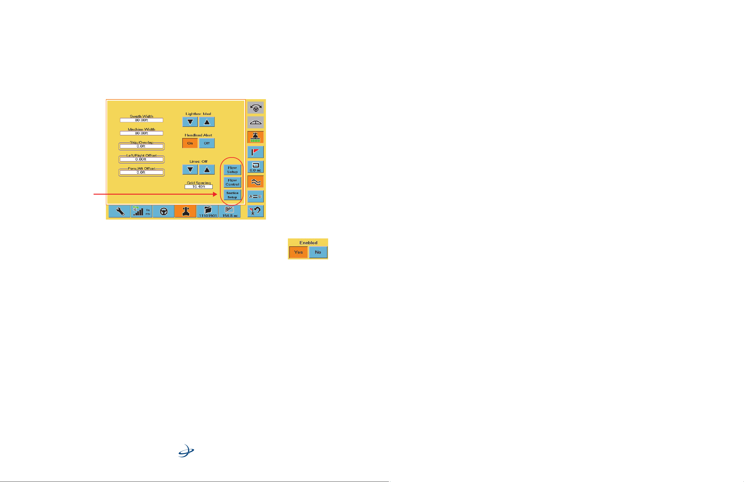
You perform AC110 setup and calibration via the Vehicle screen of the S3 (Figure 1). With AC110 installed the
Vehicle screen displays the Flow Setup, Flow Control, and Section Setup buttons.
Rate/section
control setup
buttons
Figure 1: S3 Vehicle tab with rate/section control buttons
Both flow control and section control have simple on/off controls (Enabled: Yes/No buttons)
that allow you to enable or disable the rate control and section control functionality. Once
you enable the functionality you can then perform the necessary setup and calibration.
Part No. 875-0303-000 Rev A1
AC110 Rate/Section Controller
Quick Reference Guide
2 of 21
Page 3
Flow Setup
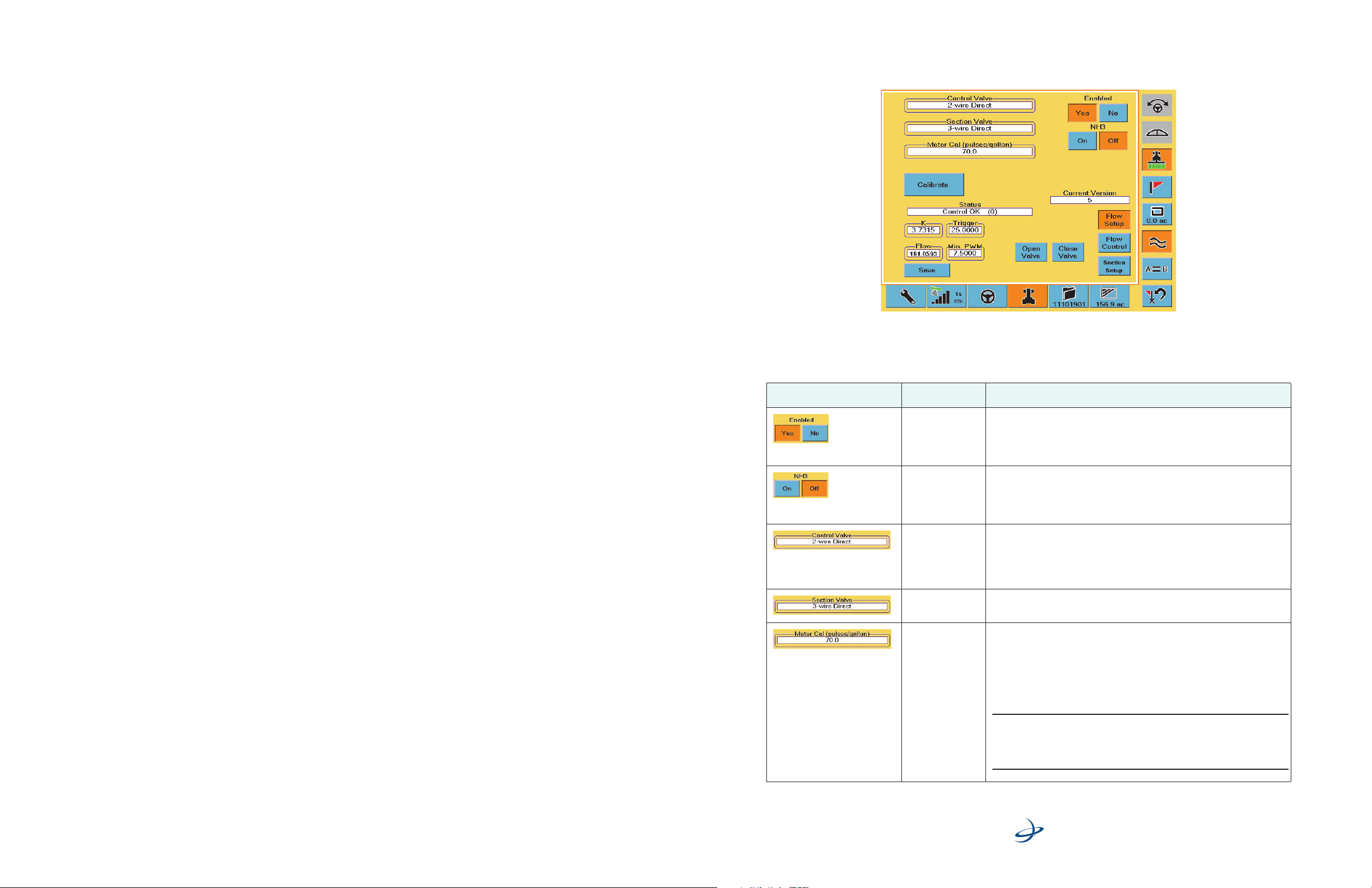
Use the Flow Setup screen (Figure 2) to set flow parameters as well as to calibrate flow. See “Flow Calibration”
on page 6 for instructions on performing flow calibration.
Figure 2: Flow Setup screen
Before you begin flow setup review the screen item descriptions in Table 1 below:
Table 1: Flow Setup screen item descriptions
Screen Item Name Description
Enabled buttons Press Yes to enable the Flow Setup screen buttons/fields and enable
NH3 (anhydrous
ammonia)
buttons
Control Valve
field
Section Valve
field
Meter Cal field Locate the meter calibration tag or stamp on the flow meter and the
rate control functionality on the S3.
Pres No to disable the Flow Setup screen buttons/fields and disable
rate control functionality on the S3.
Set to On for NH3 control. Rate will be in lbs nitrogen/acre (US) or kgs
nitrogen/hectare (metric). Volume remaining in tank will be lbs or kgs
of NH3.
Set to Off to set any other liquid as the application liquid.
Identify the wiring going to the regulating valve and determine if there
are 2 or 3 wires. Most sprayers will be 2-wire unless plumbed by-pass
(flow diverted back to tank), in which case it may be 2-wire inverse. A
good way to check is to open the valve and if pressure increases, the
correct valve has been selected.
Identify the wiring going to boom valves—most will be 3-wire Direct.
corresponding calibration value.
• For Raven systems, divide the calibration number by 10 and
enter this number.
Example: If 169 is the calibration value, enter 16.9.
• For TeeJet meters, enter the number as is.
Part No. 875-0303-000 Rev A1
Note: Many TeeJet meters list the calibration value in pulses/liter. It
may be easier to change the units of measure in the S3 to metric,
enter the meter calibration, and then change units of measure back to
US.
AC110 Rate/Section Controller
Quick Reference Guide
3 of 21
Page 4
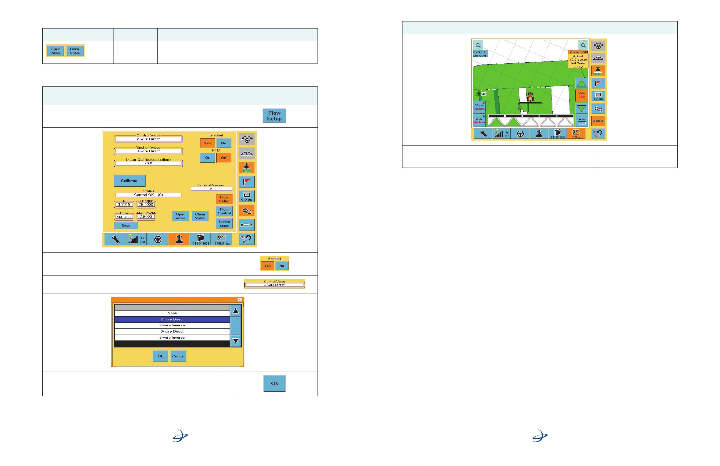
Table 1: Flow Setup screen item descriptions (continued)
Screen Item Name Description
Step Screen Item (when applicable)
Open Valve/Close
Valve buttons
Useful in manually opening and closing the regulating valve to
identify if an incorrect Control Valve option was selected or if a cable is
not connected.
To perform flow control setup complete the following steps:
Step
1. On the Vehicle tab of the S3 press the Flow Setup button. The Flow Setup
screen appears.
Screen Item
(where applicable)
4. Make an initial pass around your desired boundary to set it in the S3. AC110
automatically turns off booms when approaching a field boundary or no-spray
zone.
2. Make sure flow control is enabled (make sure the Ye s button is selected for
Enabled).
3. Press the Control Valve field. The Control Valve list appears.
4. Select an item in the list and press Ok.
Part No. 875-0303-000 Rev A1
4 of 21
AC110 Rate/Section Controller
Quick Reference Guide
Part No. 875-0303-000 Rev A1
AC110 Rate/Section Controller
Quick Reference Guide
21 of 21
Page 5
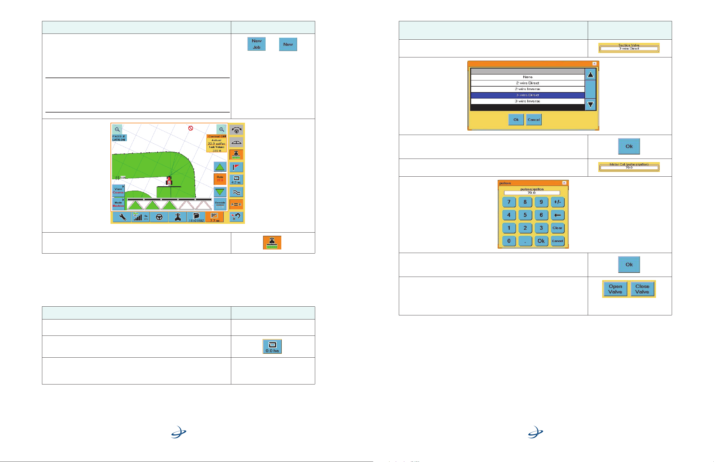
Step Screen Item (when applicable)
2. Press New Job in the Getting Started window or press New on the Job screen,
and then begin driving your field. AC110 will begin application when:
• Apply button is ON
• Ground speed is detected
• AC110 recognizes that boom sections are in an unapplied area
Note: The Section Status bars and Section icons at the bottom of the screen
indicate mode (auto or forced on/off) and spray status (spraying or not spraying).
See Table 5 on page 14 for more information on the Section Status bars and Section
icons. Also see Table 6 on page 16 for sample scenarios and what the Section Status
bars and Section bars indicate in those scenarios.
Step
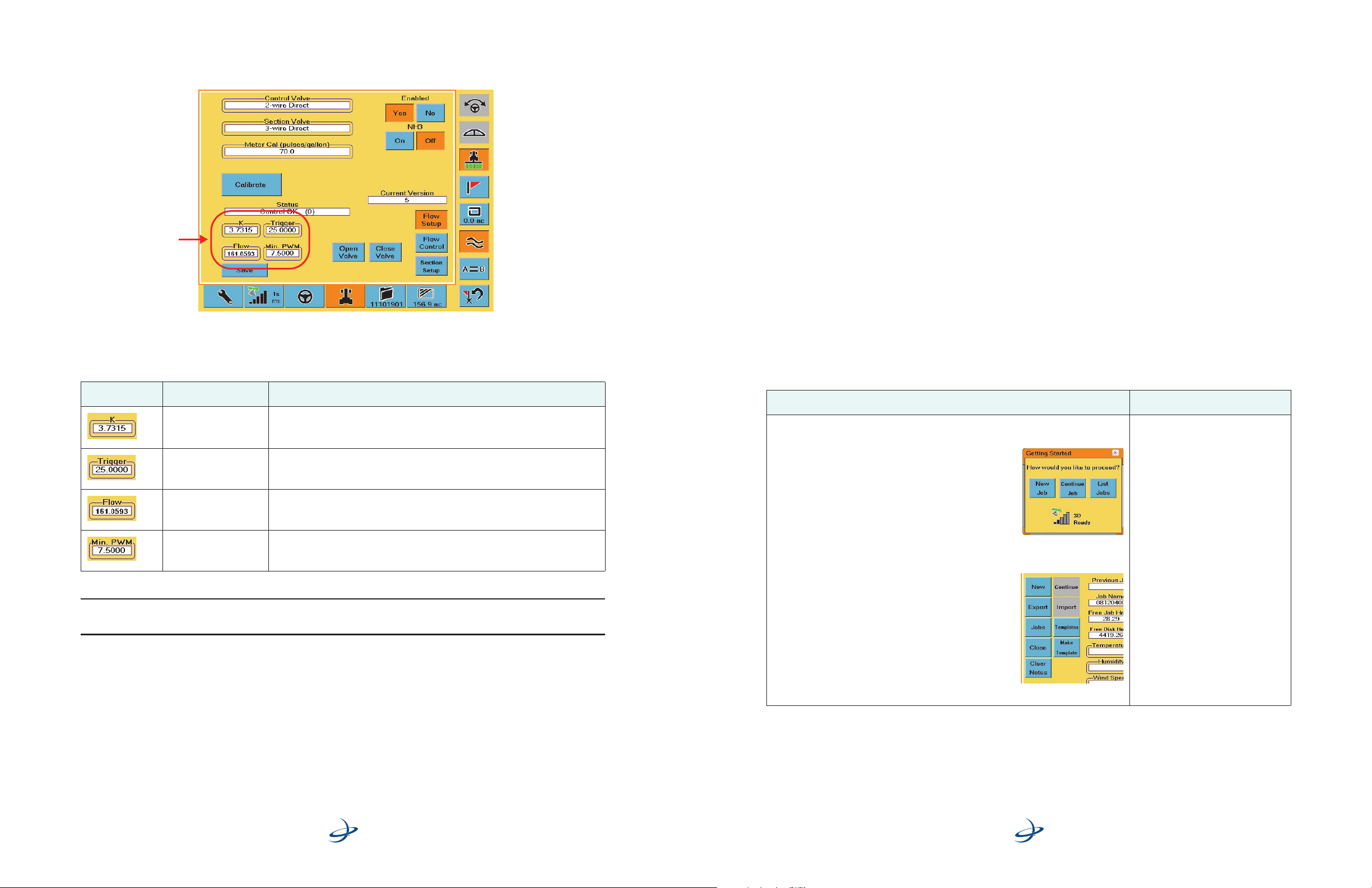
5. Press the Section Valve field. The Section Valve list appears.
6. Select an item in the list and press Ok.
7. P r e ss t h e Meter Cal field. The Meter Cal window appears.
Screen Item
(where applicable)
3. Using the Map screen as a guide, press the Apply button to enable spraying.
Creating Field Boundaries and No Spray Zones
For help creating field boundaries and no-spray zones, refer to the Outback S3 User Guide. This section
provides a brief overview of using field boundaries and no-spray zones with AC110.
To create field boundaries and no-spray zones:
Step Screen Item (when applicable)
1. Start a standard AC110 Job (see “Beginning a Basic Spray Job Using AC110” on
page 19).
2. On the S3 press the Perimeter button. The Perimeter window appears.
3. Set the desired boundary settings:
• Select “Include” to set a field boundary
• Select “Exclude” to set a no-spray zone
8. Enter a value and press Ok.
9. Optional: If you selected an incorrect Control Valve option or if a cable is not
connected you can identify the problem using the Open Valve and Close Valve
buttons:
•Press the Open Valve button to manually open the valve
•Press the Close Valve button to manually close the valve
Part No. 875-0303-000 Rev A1
20 of 21
AC110 Rate/Section Controller
Quick Reference Guide
Part No. 875-0303-000 Rev A1
AC110 Rate/Section Controller
Quick Reference Guide
5 of 21
Page 6
Flow Calibration
After you perform flow setup you should calibrate the flow. You perform flow calibration from the Flow Setup
screen (Figure 3).
Calibration
fields
S3 Jobs and the AC110
This section describes how to use jobs on the S3 with AC110 functionality.
Job Types
Outback S3 with AC110 supports four types of jobs:
• Standard job - The simplest way to use AC110 is to start a job in the S3 and begin spraying. AC110
will generate an as-applied record of spray activity.
• Job with field boundary (include) - AC110 allows you to create a no-spray boundary by creating a
field boundary in S3. After making an initial spray pass around the field boundary, AC110 will create a
no-spray zone around the field boundary.
• Job with no-spray zones (exclude) - AC110 allows you to create no-spray zones within a job. This is
a useful feature for areas such as waterways, well heads, and other no-spray areas. Set the no-spray
zones in the S3 and drive around the no-spray zone while spraying. AC110 will create a no-spray zone
within the area sprayed around and turn off any boom sections that enter the no-spray zones.
• Job with field boundary and no-spray zones - For complete control, you can generate both a field
boundary and up to eight no-spray zones for a job. Simply use the field boundary and no-spray zone
menus on the S3 and spray around the areas that are not to be sprayed.
Figure 3: Flow Setup screen - calibration fields
Before calibrating the flow review the screen item descriptions in Table 2 below:
Table 2: Flow Setup screen item descriptions for calibration
Screen Item Name Description
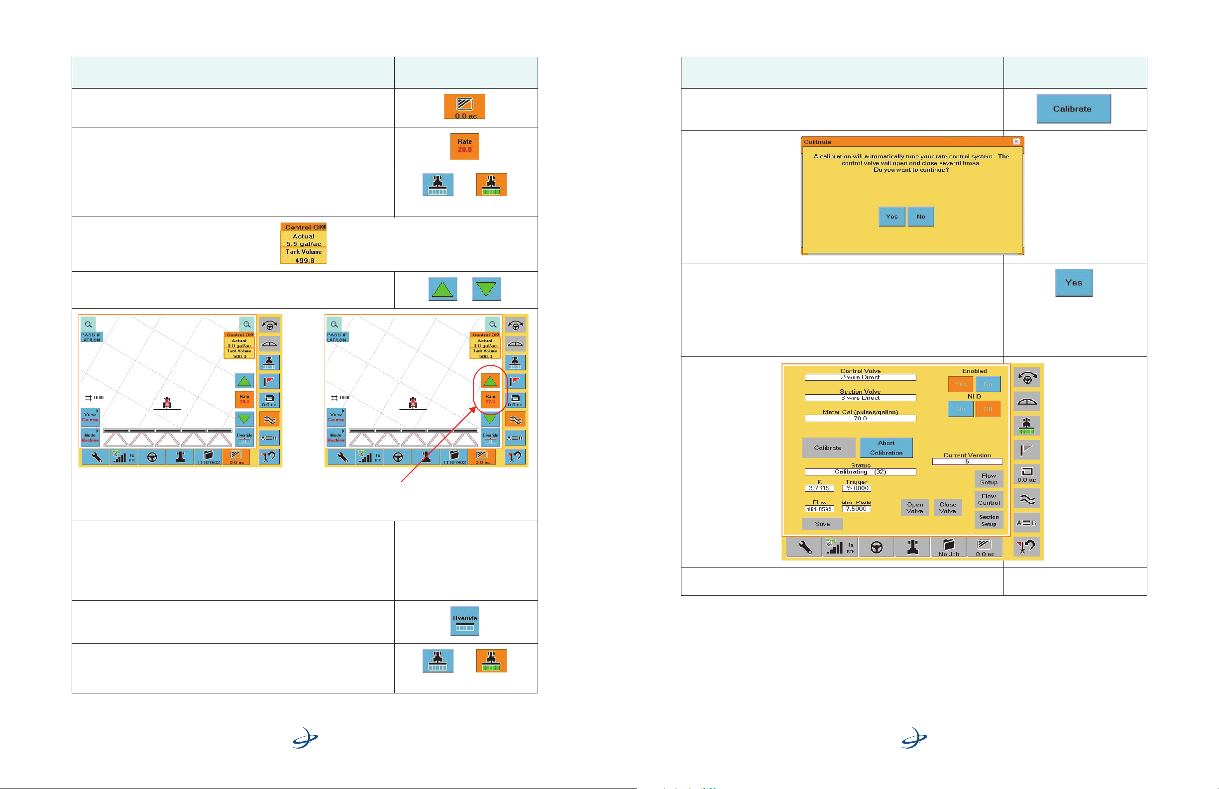
K field Gain, or how fast the system attempts to hit the target rate.
Trigger (l/min) field How soon before the target rate the system switches to fine control.
Flow (l/min) field Distance between (range) high flow and low flow.
Min PWM field Minimum current needed to get the valve to move.
Note: The four calibration fields described in Table 2 are blank before calibration and are populated when
calibration is complete (successful).
Beginning a Basic Spray Job Using AC110
Before beginning a job, configure basic job settings. See “Section Setup” on page 11 for configuration
instructions.
To begin a basic spray job:
Step Screen Item (when applicable)
1. After powering on the S3 and pressing Accept, the Getting Started screen
appears with the following options:
• New Job: Begins a new job.
• Continue Job: Continues a previous job.
• List Jobs: Displays a list of jobs.
or
If you are already on another S3 screen, press the
Job tab to display the Job screen.
Getting Started window
You can perform calibration with the vehicle parked or moving. Perform the following before calibrating the
flow:
• Make sure the tank is clean with several hundred gallons of water.
• Unfold the booms and move the vehicle to a safe location.
• Make sure the vehicle is running at the operating RPM used for spraying.
During the calibration process the system will open and close the regulating valve several times.
Part No. 875-0303-000 Rev A1
6 of 21
AC110 Rate/Section Controller
Quick Reference Guide
Part No. 875-0303-000 Rev A1
Job buttons on Job screen
AC110 Rate/Section Controller
Quick Reference Guide
19 of 21
Page 7
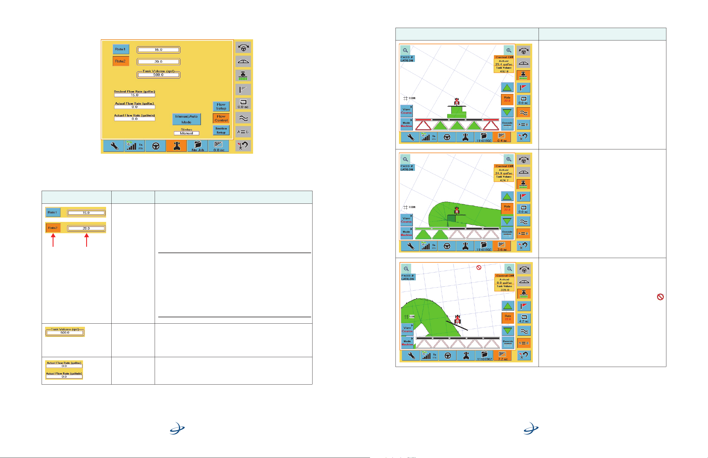
To use rate/section control complete the following steps:
To perform flow calibration complete the following steps:
Step
1. P r e s s th e Map tab to display the Map screen.
2. Toggle the Rate button to select the rate to apply. When you press the Rate
button the new target rate appears on the button.
3. Press the Apply button (set it to ON) and begin driving. The actual rate appears
in the upper right of the screen.
4. To increase or decrease the selected target rate incrementally press the Up or
Down arrow buttons.
Screen Item
(where applicable)
Step
Screen Item
(where applicable)
1. Make sure you are on the Flow Setup screen and then press the Calibrate
button. The Calibrate window appears.
OnOff
2. Press Ye s. The calibration process starts and may take up to 10 minutes.
During calibration:
• The Abort Calibration button appears to the right of the Calibration button.
Press the Abort Calibration button to stop the calibration process.
• All other buttons/fields on the screen are gray (unavailable).
• The Status field displays “Calibrating” and a number counting up to indicate
calibration progress.
The rate displayed on the Rate button changes and the Up/Down arrow button
you pressed changes color. In this example the Up arrow button color and the
rate displayed on the Rate button show the target rate was increased to 22.0.
5. To override individual sections press the appropriate Section icons. The Section
Status bars change from Auto (black bar) to Off (red outline) to On (green bar)
and back to Auto.
• Auto: turns sections On and Off based on previously applied areas
• Off: section remains Off even if in an unapplied area
• On: section remains On even if in a previously applied area
6. To toggle all sections between an Auto state and forced On state press the
Override button.
7. If you need to turn off all sections at any time press the Apply button.
Part No. 875-0303-000 Rev A1
18 of 21
OnOff
AC110 Rate/Section Controller
Quick Reference Guide
3. Once calibration is complete the text “Calibration Success” appears in the
Status field.
Part No. 875-0303-000 Rev A1
7 of 21
AC110 Rate/Section Controller
Quick Reference Guide
Page 8
Flow Control Setup
Rate
buttons
Rate
fields
Use the Flow Control screen (Figure 4) to set flow control parameters.
Figure 4: Flow Control screen
Before you begin flow control setup review the screen item descriptions in Table 3 below:
Table 3: Flow Control screen item descriptions
Screen Item Name Description
Rate 1 button and
field
Rate 2 button and
field
Enter a predefined rate. You can change this number on the fly during
application.
Enter a second predefined rate. You can change this number on the fly
during application.
Table 6: AC110 Map screen scenarios (continued)
Map Screen Scenario
Spraying enabled (Apply button pressed)
Auto mode enabled (“Rate” and rate value appear on
Rate button, Section Status bars are black for three
middle sections)
Two outer sections manually turned off (Section icons
pressed)
• Section Status bars red indicate manual off
• Section icons: red outline indicates manual
mode, white interior indicates no spraying
Spraying occurring in three middle sections (Section
icons are green)
Actual rate and current tank volume displayed in upper
right of screen
Actual rate above Target rate
Spraying enabled (Apply button pressed)
Auto mode enabled (“Rate” and rate value appear on
Rate button, Section Status bars are black for three right
sections)
Two left sections manually forced on (Section icons
pressed)
• Section Status bars green indicate forced on
• Section icons: green outline indicates manual
mode, green interior indicates spraying
Spraying occurring in two left sections (Section icons
are green)
Actual rate and current tank volume displayed in upper
right of screen
Actual rate above Target rate
Part No. 875-0303-000 Rev A1
Note: Pressing a Rate button and pressing a Rate field represent two
different functions.
• Pressing a Rate button makes that rate the default rate in use
and displayed on the Map screen. On the Map screen you can
toggle between the two rates by pressing the rate buttons. See
“Section Setup” on page 11 for information on changing the
rate from the Map screen.
• Pressing a Rate field displays the Desired Flow Rate window,
allowing you to adjust the flow rate.
Tank Volume field Enter the volume of product in the tank. You will need to adjust this
value after each load. While spraying, the S3 subtracts from this value
what has been applied and this current volume appears on the Map
screen. Refer to the Rate status area in Table 5 on page 14 for
information on remaining tank volume.
Actual Flow Rate
fields
Non-editable fields that display the actual flow rate calculated from
the flow meter.
AC110 Rate/Section Controller
Quick Reference Guide
Part No. 875-0303-000 Rev A1
Spraying enabled (Apply button pressed)
Auto mode enabled (“Rate” and rate value appear on
Rate button, Section Status bars are black for all
sections)
No spraying occurring in all sections (Section icons
are white, implement in previously sprayed area see Headland icon at top middle of Map screen)
Actual rate and current tank volume displayed in upper
right of screen
AC110 Rate/Section Controller
Quick Reference Guide
8 of 21
17 of 21
Page 9
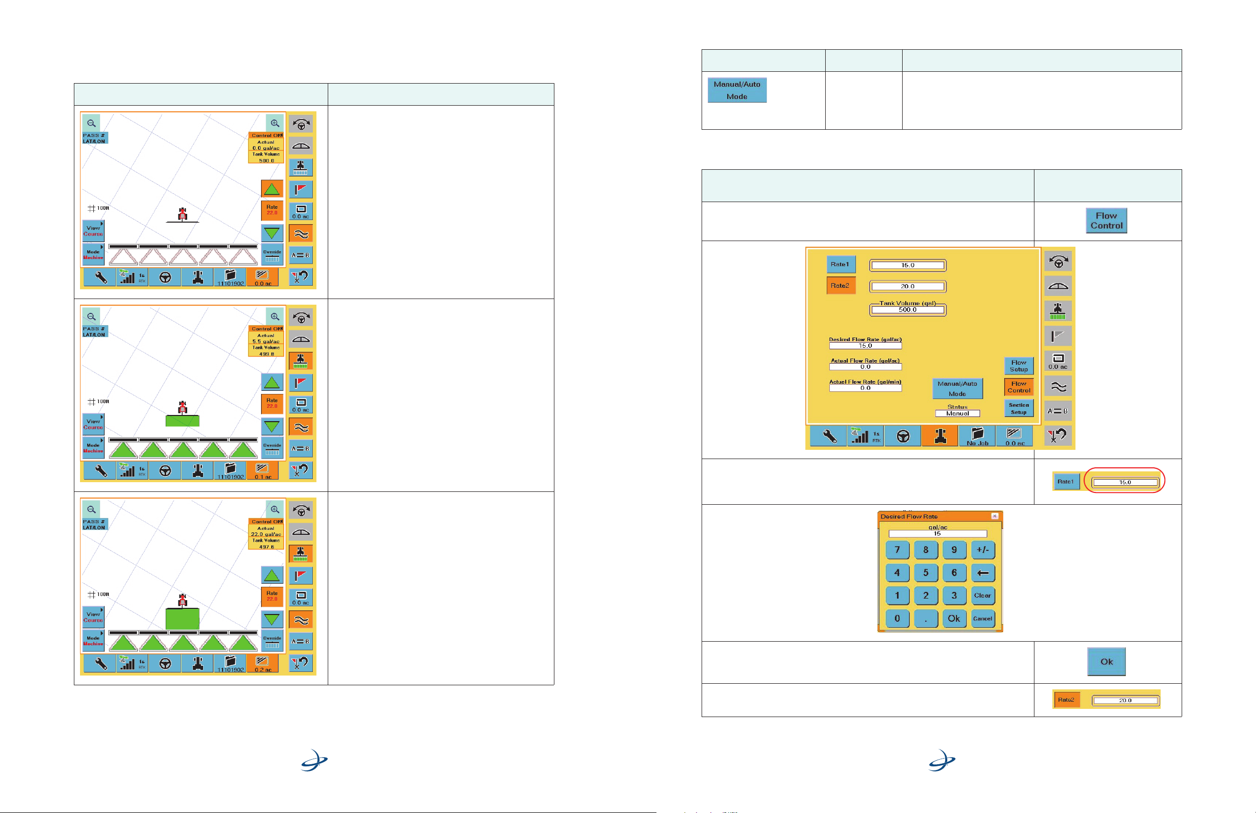
Use Table 6 to familiarize yourself with the elements of the Map screen related to rate/section control
functionality.
Table 6: AC110 Map screen scenarios
Map Screen Scenario
Target rate manually increased to 22.0 (Up arrow is
pressed and Rate button displays new target rate)
Auto mode enabled (“Rate” and rate value appear on
Rate button, Section Status bars are black)
No spraying (Apply button is not pressed, Section icons
are white)
Spraying enabled (Apply button pressed)
Auto mode enabled (“Rate” and rate value appear on
Rate button, Section Status bars are black)
Spraying occurring in all sections (Section icons are
green)
Actual rate and current tank volume displayed in upper
right of screen
Table 3: Flow Control screen item descriptions (continued)
Screen Item Name Description
Manual/Auto
Mode button
Toggles between:
• Manual mode where the control valve is forced open and
closed using the Up and Down buttons on the Map screen
• Auto mode
To perform flow control setup complete the following steps:
Step
1. On the Vehicle tab of the S3 press the Flow Control button. The Flow Control
screen appears.
Screen Item
(where applicable)
Part No. 875-0303-000 Rev A1
Spraying enabled (Apply button pressed)
Auto mode enabled (“Rate” and rate value appear on
Rate button, Section Status bars are black)
Spraying occurring in all sections (Section icons are
green)
Actual rate and current tank volume displayed in upper
right of screen
Target rate reached (Actual rate is equal to Target rate on
Rate button)
AC110 Rate/Section Controller
Quick Reference Guide
2. Press the Rate 1 field. The Desired Flow Rate window appears for Rate 1.
3. Enter a flow value and press Ok.
4. Repeat steps 2 and 3 for Rate 2.
Part No. 875-0303-000 Rev A1
AC110 Rate/Section Controller
Quick Reference Guide
16 of 21
9 of 21
Page 10
Actual rate is
+/-20% or more
from target rate
Manual
mode
Step
Screen Item
(where applicable)
Table 5: Map screen item descriptions for rate/section control (continued)
Screen Item Name Description
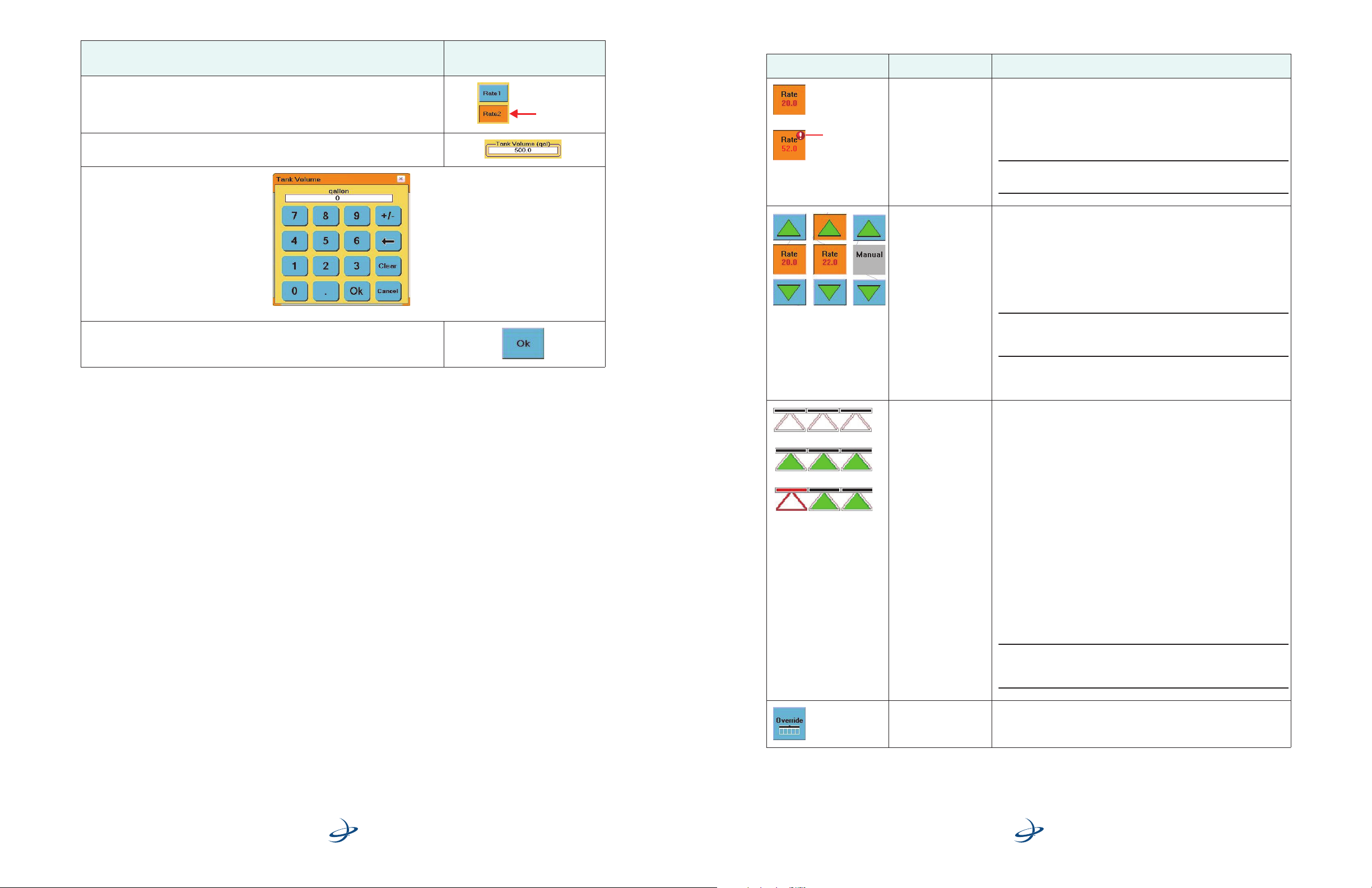
5. Press the desired Rate button (Rate 1 or Rate 2) to make that rate the default rate
in use. An orange button indicates the selected button. In the figure to the right
Rate 2 is the selected rate.
6. Press the Tank Volume field. The Tank Volume window appears.
7. Enter the tank volume and press Ok.
Selected rate
Before After
rate
change
rate
change
Rate button Press the Rate button to select the rate to apply (toggle between
Rate 1 and Rate 2). When you first display the Map screen the rate
indicated on the Rate button correlates to the Rate button (Rate 1 or
Rate 2) you pressed on the Flow Control screen. See “Flow Control
Setup” on page 8 for more information on the Rate buttons of the
Flow Control screen.
Note: If the actual rate is +/- 20% or more from the target rate a red
exclamation point is displayed on the Rate button.
Up and Down Arrow
buttons
If rate control is enabled press the Up and Down arrows to increase/
decrease the target rate in 1 gallon or 10 liter increments.
When you press either button to change the rate:
• That button changes color to indicate you increased/
decreased the rate
• The rate displayed on the Rate button increments/
decrements
Note: You enable rate control by pressing Yes in the Enable area of
the Flow Setup screen). See “Flow Setup” on page 3 for more
information on enabling/disabling rate control.
In Manual mode press the Up and Down arrows to force the control
valve open (Up arrow) or closed (Down arrow).
Section Status bars
(horizontal bars above
the triangles)
Section icons
(triangles)
The figures to the left
only represent some
of the possible
combinations of
different color Section
Status bars and
Section icons.
Each Section icon (triangle) represents one section. For example, if
there are 6 sections then six Section icons (triangles) appear at the
bottom of the Map screen.
For each section triangle there is a horizontal bar (Section Status bar)
above it that indicates the section status.
Each Section Status bar can be one of three colors:
• Black (Auto mode)
• Green (manually forced ON)
• Red (manually forced OFF)
Each Section icon can have different colors for the outline of the
triangle and the interior of the triangle:
• Outline white (Auto mode)
• Outline green or red (Manual mode)
• Interior green (manually forced ON - spraying)
• Interior white (Auto mode - no spraying)
• Interior red (manually forced OFF - no spraying)
Part No. 875-0303-000 Rev A1
10 of 2 1
AC110 Rate/Section Controller
Quick Reference Guide
Part No. 875-0303-000 Rev A1
Note: See Table 6 on page 16 for an overview of how different AC110
scenarios are represented on the Map screen (including the different
colors of the Section Status bars and Section icons).
Override button Press the Override button to toggle all sections between an Auto
state and forced On (opens all section valves) state.
AC110 Rate/Section Controller
Quick Reference Guide
15 of 21
Page 11
Using Rate/Section Control
When using rate/section control you can:
• Increase or decrease the Target rate incrementally
• Override individual sections
• Toggle all sections between an Auto state and forced On state
• Turn off all sections at any time
• Change the rate while operating
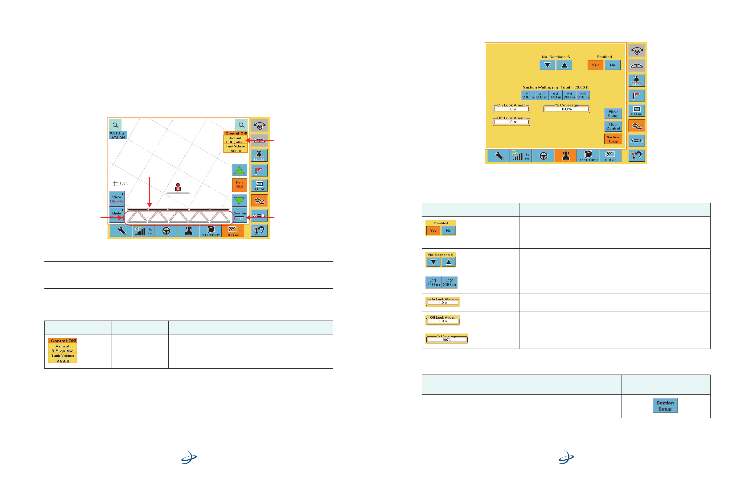
After you set your rate/section control parameters you work with rate/section control via the Map screen
(Figure 6).
Rate status area
Section Setup
Use the Section Setup screen (Figure 5) to set section control parameters.
Section status
# of sections
Figure 6: Map screen showing rate/section control
Override button
Note: When AC110 is connected and powered on, the Machine Width field on the Vehicle screen is read-only.
When AC110 is powered off, the Machine Width field is editable. This allows the S3 to store the settings for rate
and section control, but also allows you to change the machine width for other uses.
Before you begin using rate/section control review the screen item descriptions in Table 5 below:
Table 5: Map screen item descriptions for rate/section control
Screen Item Name Description
Rate status area The rate status area displays the following information:
• Actual - actual spray rate
• Tank Volume - volume remaining in tank
Figure 5: Section Setup screen
Before you begin section setup review the screen item descriptions in Table 4 below:
Table 4: Section Setup screen item descriptions
Screen Item Name Description
Enabled buttons Press Yes to enable the Section Setup screen buttons/fields and enable section
control functionality on the S3.
Press No to disable the Section Setup screen buttons/fields and disable section
control functionality on the S3.
No. Sections
buttons
Section Widths
buttons
On Look Ahead
field
Off Look Ahead
field
% Coverage field Enter the percentage of the boom section that must enter or exit a previously
Select the number of sections.
Enter the section width for each section (up to ten sections, one button for each
section).
Enter the number of seconds needed to open the boom valves and build
pressure ahead of an unapplied area. Increase the number to turn on sooner.
Enter the number of seconds needed to close the boom valves ahead of a
previously applied area. Increase the number to turn off sooner.
applied area before AC110 will turn it off or on.
To perform section setup complete the following steps:
Part No. 875-0303-000 Rev A1
14 of 21
AC110 Rate/Section Controller
Quick Reference Guide
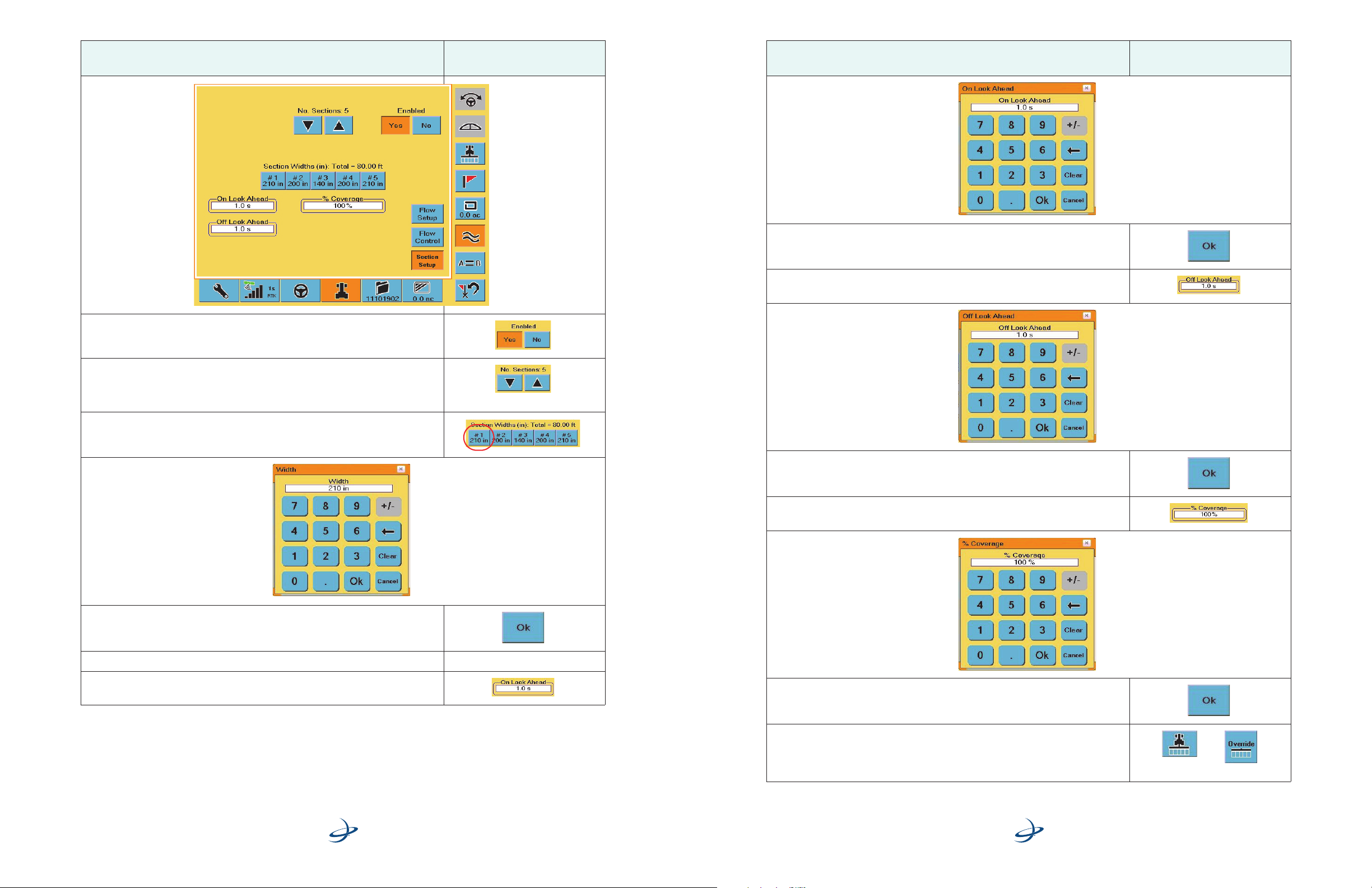
Step
1. On the Vehicle tab of the S3 press the Section Setup button. The Section Setup
screen appears.
Part No. 875-0303-000 Rev A1
11 o f 2 1
Screen Item
(where applicable)
AC110 Rate/Section Controller
Quick Reference Guide
Page 12
Step
2. Make sure section control is enabled (make sure the Yes button is selected for
Enabled).
3. Press the No. Sections buttons (up or down) to select the number of sections.
As you press these buttons the number of Section Widths buttons
corresponding to the number above the No. Sections buttons appear/disappear
in real time.
Screen Item
(where applicable)
Step
8. Enter an on look ahead value and press Ok.
9. Press the Off Look Ahead field. The Off Look Ahead window appears.
Screen Item
(where applicable)
4. Press the first Section Width button. The Width window appears.
5. Enter a width value and press Ok.
6. Repeat steps 3 and 4 for each additional Section Width button.
7. P r e ss t h e On Look Ahead field. The On Look Ahead window appears.
10. Enter an off look ahead value and press Ok.
11. Pr e ss th e % Coverage field. The % Coverage window appears.
12. Enter a % coverage value and press Ok.
13. To test the sections were set up correctly press the Apply button (set it to ON,
orange) and then override individual sections or press the Override button to
override all sections. See Table 5 on page 14 for more information on the
Override button and other AC110-related Map screen features.
Apply
Override
Part No. 875-0303-000 Rev A1
12 of 21
AC110 Rate/Section Controller
Quick Reference Guide
Part No. 875-0303-000 Rev A1
AC110 Rate/Section Controller
Quick Reference Guide
13 of 21
 Loading...