

Page 1
Installation & Calibration
Phone (816) 796-2900
Fax. (816) 796-3333
Email [email protected]
HEMCO Corporation
711 S. Powell Road
Independence MO, 64056
MM-TEL-AIRFLOW-500.07.14
Visit www.HEMCOcorp.com Call Toll Free: (800) 779-4362
Lab Planning Solutions
HEMCO
R
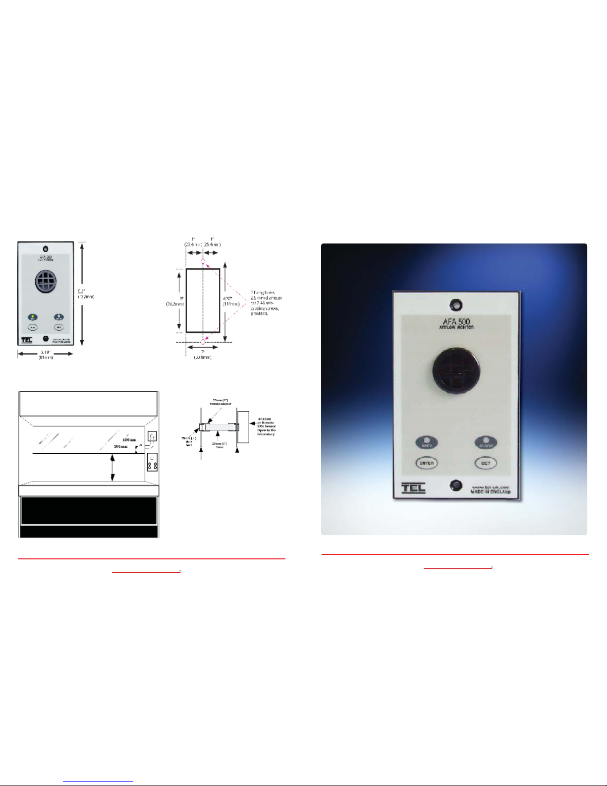
The monitor or sensor must be positioned
where it can ‘see’ the room pressure of the
laboratory. The back connection spigot of the
monitor or sensor will accept the 25mm (1”)
hose which should be connected to the inner
chamber of the fume hood. The ideal position
for the hose connection is 100mm (4”) back
from the sash and 100mm (4”) higher than the
normal sash opening height.
AFA500 or Remote Airfl ow Sensor Installation Diagram
Monitor Panel Dimensions
Monitor Panel Cutout Dimensions
Fume hood
inner skin
Fume hood
outer skin
Normal Sash
working height
TEL Airfl ow Monitor Model AFA 500 MK 3
Installation, Operation, Maintenance Manual
Phone (816) 796-2900
Fax. (816) 796-3333
Email [email protected]
HEMCO Corporation
711 S. Powell Road
Independence MO, 64056
Visit www.HEMCOcorp.com Call Toll Free: (800) 779-4362
Lab Planning Solutions
HEMCO
R
Page 2
2
Model # AFA 500 MK3 Airfl ow Monitor
STARTUP
The AFA500 MK3 must be fi eld-calibrated once the room air supply and exhaust is balanced.
When the unit is powered up, the following sequence of events occurs:
1. The alarm performs a self-test of its functions, LEDs and audible alarm (approximately 2
seconds) and then initiates a delay timer of 30 seconds to allow the airfl ow sensor to stabilize.
2. During the 30-second stabilizing period, all alarms and relay outputs are deactivated and
the red and green LEDs remain on.
3. At the end of the delay, the unit will do one of two things:
a. If the monitor has been calibrated, the unit enters normal operating mode (solid green light
for safe velocity, red light and audible alarm if low velocity).
b. If the unit has not been calibrated, the red and green LEDs will fl ash, the audible alarm
will be muted.
CALIBRATION Single Point (default)
1. Determine the required low air alarm point, then position the sash and use a calibrated
instrument so that the face velocity is equal to the required alarm point.
2. Press and hold the Enter button for 5 seconds to enter Calibration Mode. This is indicated by
both red and green LEDs fl ashing with the audible alarm beeping.
3. To initiate calibration, press and hold the Enter and Set buttons at the same time. The unit
will sample the airfl ow for 5 seconds, during which time the green LED goes off and the red
LED fl ashes. The audible alarm continues to sound during the air sampling.
4. If calibration is successful, the monitor will give a two-tone beep at the end of the air sample,
and then automatically enter run mode.
5. If the Enter or Set button is released during the air sampling period, or if the airfl ow is fl uctuating
too much, the alarm will emit a lower-frequency buzzing for a short period and then re-enter
calibration mode. If this occurs, press the Enter and Set buttons again to repeat the airfl ow
sampling.
6. When the calibration is complete, lower the sash to the normal operating height and the Green
LED should be illuminated, indicating that the airfl ow is greater than the calibrated alarm point.
If, during normal operation, the airfl ow drops below the alarm point, the unit will go into alarm
condition (red LED fl ashing, audible horn beeping). Push the enter button to temporarily mute
the horn.
7. The horn can be permanently disabled by pressing and holding the Set button for 10 seconds.
The horn will sound 3 times to indicate that it has been disabled. In Safe mode the Green LED
will fl ash if the horn is disabled or be solid to indicate that the horn is enabled. To enable the
horn press and hold the Set button for 10 seconds, the horn will sound 3 times to indicate that
it has been enabled.
3
Installation & Calibration
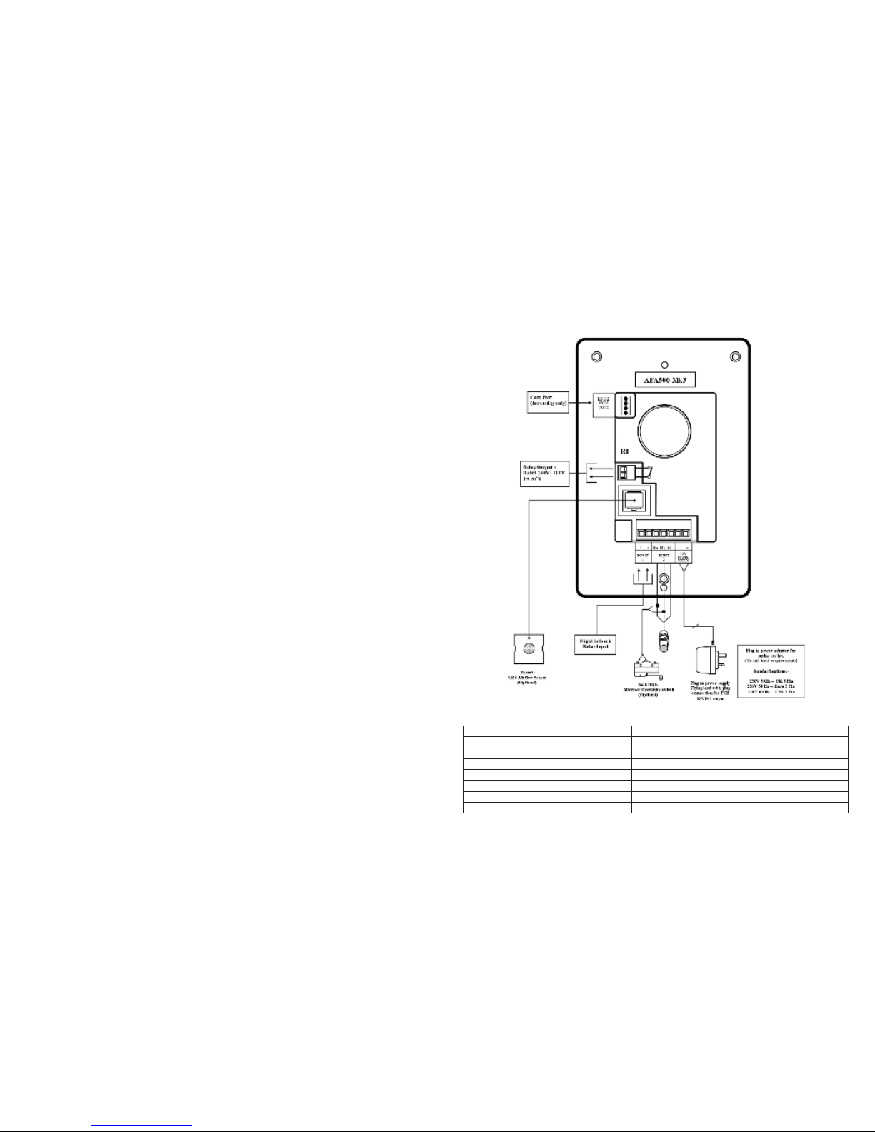
Horn Red LED Green LED Operation
Beep* 1 On On Power up 30 second time period to allow sensor stabilization
Off Flashing Flashing Requires Calibration - follow calibration procedure
Off Off On Air SAFE - audible alarm enabled
Off Off Flashing Air SAFE - audible alarm permanently disabled
On On Off Air Fail
Off On Flashing Air Fail - Setback mode (remote horn mute activated)
On Flashing Off Sash High alarm
Operation
 Loading...