

Page 1
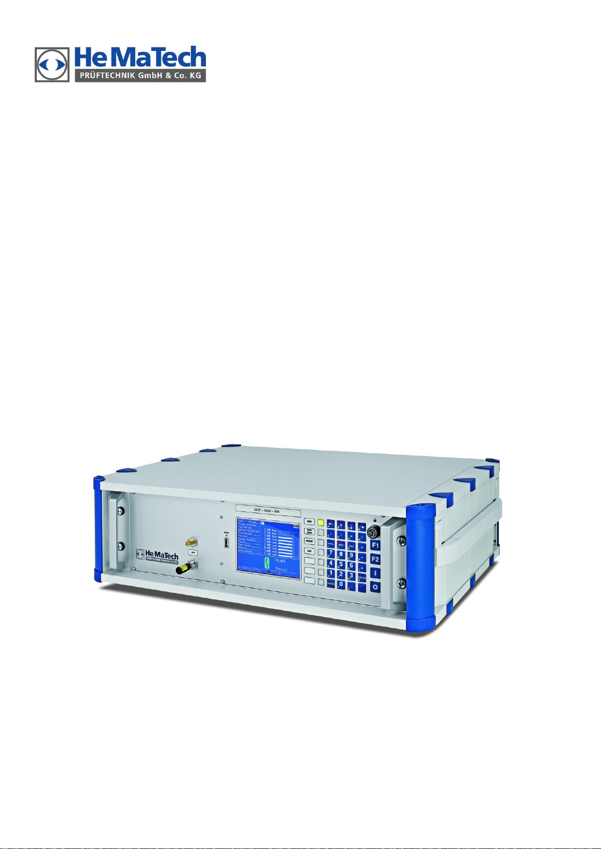
leak test flow test volume test test systems test machines
Leak Tester 3925 – 0060
Operating Instructions
EN 3925-0060 V207-00 MANUAL R03.doc
Please read these instructions, before installing, starting up, storing or handling this device.
Page 2

Any trademarks referred to in this manual are the
sole property of the corresponding owner.
HeMaTech Prüftechnik GmbH & Co. KG
Siemensstrasse 7
DE-71409 Schwaikheim
Phone +49 (0)71 95/13 69 0
Fax +49 (0)71 95/13 69 29
Internet http://www.hematech.de
© 2010 All rights reserved
Edition 07/2010
EN 3925-0050 V205-00 MANUAL R01.doc
Page 3

Contents
Leak Tester 3925 – 0060 ................................................... 1
Operating Instructions ........................................................ 1
Introduction ...................................................................... 7
Concerning these operating instructions ................................................. 7
Intended use ....................................................................................... 8
Warranty............................................................................................. 9
Structure of the manual ...................................................................... 10
Safety measures .............................................................. 12
Safety notes ....................................................................................... 12
Symbols used .................................................................................... 14
Product description .......................................................... 15
The differential pressure method .......................................................... 15
Performance characteristics ................................................................. 18
Design and working principle .............................................................. 19
Scope of delivery ............................................................................... 20
View of device ................................................................................... 21
Control elements ............................................................................... 23
Installation and start-up ................................................... 25
Connecting peripheral equipment ........................................................ 25
Switching the device ON and OFF ....................................................... 28
Initializing ....................................................................... 29
The display ..................................................................... 30
Working with the program .................................................................. 31
Using the write protection switch .......................................................... 31
Command reference ........................................................ 32
Program structure .............................................................................. 32
Menu 1. AUTOMATIC ........................................................................ 33
Sequencer ........................................................................................... 35
Automatic mode without leak simulation ................................................. 36
Menu 2. MANUAL ............................................................................. 37
1. Test ................................................................................................ 37
1.1 Determination of a reference record ................................................. 39
1.1 Sequencer ..................................................................................... 40
2. Pressurize (Flooding) ......................................................................... 42
Menu 3. SETUP ................................................................................. 44
1. Set parameter (Test program) ............................................................. 44
1.1 Printout PARAMETER ....................................................................... 51
1.2 Copying an existing test program ..................................................... 53
2. Date & Time. ................................................................................... 54
3. Serial ports ...................................................................................... 55
3.1 Output format Profibus .................................................................... 62
Page 4

3.2 Output format Profinet .................................................................... 67
4. Sequencer ........................................................................................ 77
4.1 Printout SEQUENCER PARAMETER .................................................... 79
5. Adjusting the filling/testing pressure manually (option 0050-04) ............. 81
6. Adjusting the vacuum manually (option 0050-01) ................................. 83
Menu 4. DELETE ............................................................................... 84
Menu 5. PRINT MENU ....................................................................... 85
1. View Program Status .......................................................................... 85
2. Data Collection ................................................................................ 86
2.1 Print Data Collection ....................................................................... 87
3. Operating data................................................................................. 88
4. Counter ........................................................................................... 88
5. Backup ............................................................................................ 89
6. Error counter status ........................................................................... 90
7. Record ............................................................................................. 91
8. Record Reverence ............................................................................. 93
Menu 6. SETTINGS ........................................................................... 95
1. Display ............................................................................................ 95
2. System parameters ............................................................................ 97
3. Pressure control ................................................................................ 99
4. System status .................................................................................... 101
5. Options ........................................................................................... 102
Testing and Setup .......................................................... 104
Testing the leak tester .......................................................................104
Setting up the device for specimen .....................................................106
Leak simulation (option) ....................................................................107
Maintenance ................................................................. 108
Maintenance contract .......................................................................108
Maintenance plan ............................................................................108
Errors, Causes and Remedy ...............................................................109
Acknowledging error messages ..........................................................109
Trouble Shooting Chart .....................................................................110
Signal Exchange with Machine Control ............................ 114
Automatic operation .........................................................................115
In semi-automatic operation ..............................................................118
Sample printouts ........................................................... 122
Protocol printout ..............................................................................122
Program parameters .........................................................................123
Result memory .................................................................................124
System parameters............................................................................125
Appendix ...................................................................... 127
Plug assignment ...............................................................................128
Pneumatic diagram (vacuum device) ..................................................128
Pneumatic diagram (overpressure device) ............................................130
Technical Data .................................................................................130
Page 5

EC - Declaration of Conformity ......................................................... 133
Index .............................................................................................. 134
Contact address: ............................................................................. 138
Page 6

Page 7

Introduction
In this chapter you will find some introductory remarks concerning the use of this tester, as well as explanations concerning the structure of these operating instructions and
the symbols and text markings used in this manual.
The installation instructions for the device address to persons (skilled electricians and
service engineers) who are entrusted with the installation and maintenance of the device. These persons must be fully familiar with and strictly follow all regulations concerning electrical engineering.
The installations for operation of the completely installed device are intended for all
persons who will use and make adjustments to the device.
Concerning these operating instructions
The following pages will inform you about the proper use of the device in your production or testing environment.
HeMaTech Prüftechnik attaches great importance to the safe, appropriate and economical use of the device. However, this requires that you read these operating instructions thoroughly before you install and use the device. It contains important
information, which will help you to avoid dangers and enhance the reliability and service life of the device. Always keep these operating instructions close at hand near the
device and read the chapter
notes, to keep yourself and other members of staff out of danger and to avoid material
damage.
Safety measures
for your own safety. Strictly follow all
If you have any questions concerning work with the device, for which you have not
found an answer in these operating instructions, please contact:
HeMaTech Prüftechnik GmbH & Co. KG
Siemensstraße 7
D-71409 Schwaikheim
Phone +49 (0)71 95/13 69 0
Fax +49 (0)71 95/13 69 29
www.hematech.de
EN 3925-0060 V207-00 MANUAL R03 7
HeMaTech
Prüftechnik
Page 8

Intended use Introduction
8
Device type
Serial-Number:
Software-Version
Article number:
Designation:
HeMaTech
Prüftechnik GmbH & Co. KG
Siemensstraße 7 D 71409 Schwaikheim
Phone: +49 (0)71 95 – 13 69 0
Fax.: +49 (0)71 95 – 13 69 29
www.hematech.de
Type: ________________________________
Serial-No.: ________________________________
Voltage: ________________________________ V
Intended use
The leak tester 3925-0050 from HeMaTech Prüftechnik is solely intended for professional use in leak testing of work pieces by means of compressed air. Any use beyond
these limitations is considered unintended. The user solely bears any risks.
Installation and maintenance of the device must only be performed by skilled electrical
engineers.
Type plate
The type plate with model designation and serial number is located on the back of the
device.
You require this information when consulting our Customer Service Department.
Please record this information in the following table, so that it is at hand when needed:
Information about the software version can be found under 6. Settings / 2. System parameters
Ordering spare parts
Use only original spare parts from HeMaTech Prüftechnik. If you would like to order
accessories or spare parts, you not only need to specify device type and serial number,
but also article number and designation of the required components, which you can
take from the list of consumables and spare parts.
Reporting transport damage
If you discover any transport damage when unpacking the device, you should immedi-
ately contact the forwarding agent to report the loss or damage.
Please ask for a corresponding confirmation and return the package to us together
with this confirmation and the delivery note.
Preparing a return delivery
Pack the article with all accessories (see scope of delivery) in the original packing ma-
terial and return the goods to us, together with an exact fault description and the delivery note. Please frank the delivery.
EN 3925-0060 V207-00 MANUAL R03.doc
HeMaTech
Prüftechnik
Page 9

Introduction Warranty
Warranty
The warranty conditions for devices from HeMaTech Prüftechnik GmbH & Co. KG can
be found in our terms and conditions of sales and delivery.
If no other agreement has been made, the warranty period for design, material and
manufacturing faults (except consumables), as well as for the omission of explicitly
guaranteed properties, is generally 1 year, starting from the date of delivery.
We reserve the right to decide whether we will rectify a fault, deliver replacement or
submit a credit note covering the value of the goods.
In case of unintended use and damage caused by falling, water, dirt or any other external effects, warranty claims will become null and void.
Any malfunctions and damages caused by the user, such as soiling, faulty connections
and mechanical damage are excluded from warranty.
We reserve the right to invoice the repair costs for parts which had been returned for
warranty repair, but for which no or only partial warranty could be claimed.
If not agreed upon differently beforehand, HeMaTech Prüftechnik will only bear the
shipment costs for outgoing deliveries of devices and parts which are covered under
warranty.
However, if the delivery arrived with costs for HeMaTech Prüftechnik, these costs will
be added to the repair costs.
Import and/or export duties as well as costs arising for third parties must be borne by
the customer.
EN 3925-0060 V207-00 MANUAL R03.doc 9
HeMaTech
Prüftechnik
Page 10

Structure of the manual Introduction
10
Structure of the manual
This manual contains the description, installation and operation of the device. It consists of the following chapters:
Safety measures
Read and follow these safety notes, because they serve the safety of persons and
ensure the reliability and operational safety of the device.
Product description
Here you will become familiar with the device and its modules, functions and control
elements.
Installation and start-up
You must prepare the place of use for the device and provide the necessary supply
connections.
Operation
Once all preparations have been made switch on the device, set the test parameters
and start the test device.
Command reference
Here you find a complete description of the control software with all possible settings.
Maintenance
Apart from the list of maintenance intervals, this chapter also contains the trouble
shooting chart with information on faults, causes and possible remedy.
Signal exchange
This section shows which signals are used in operation with a machine control.
Sample printouts
In this section you find some examples for printouts of measurements, parameters, etc.
Appendix
This chapter contains wiring diagrams and technical data for the device.
The index
The index helps you to find required text passages quickly.
EN 3925-0060 V207-00 MANUAL R03.doc
HeMaTech
Prüftechnik
Page 11

Introduction Structure of the manual
Representation
Bold type
Designations of control keys are printed bold.
Italic type
Cross-references to other chapters or text passages are printed
italic
.
Operating steps
Operating steps are marked as follows:
Turn key switch clockwise.
Write protection is disabled, entries can be made.
Make all following entries and confirm these individually by pressing the ENTER-
key. The insertion point jumps to the next field.
Lists
Lists are marked as follows:
− Variant A
− Variant B
− Variant C
− …
EN 3925-0060 V207-00 MANUAL R03.doc 11
HeMaTech
Prüftechnik
Page 12

Safety notes Safety measures
12
Safety measures
Safety notes
Thoroughly read and strictly follow these safety notes. They serve your own safety, the
safety of other members of staff and help to avoid damage to the device and accessory parts.
Danger caused by electric current
Make sure that no fluid can enter into control cabinet, control panel or other parts of
the housing. If this should happen, immediately disconnect the device from the electric
power supply, secure the corresponding socket against reconnection and inform appropriately trained expert personnel or the customer service department of
HeMaTech.
Make sure that the electrical connecting leads are free of damage and well protected
against buckling or squashing. If you detect any damage, immediately disconnect the
device from the electric power supply, secure the corresponding socket against reconnection and inform appropriately trained expert personnel or the customer service department of HeMaTech.
Work in the electrical system – e.g. changing fuses – must only be performed by
trained expert staff. Further maintenance and repair work must only be performed by
the customer service of HeMaTech Prüftechnik or by persons who have been authorized by HeMaTech Prüftechnik.
Use this device and any connected devices only on a dedicated electric voltage.
Strictly follow all warnings and instructions given on the device.
If smoke or pungent smells causes suspicion of a defect, you should disconnect the
device from the mains supply and from any other equipment.
Take care that no other objects find their way into the inside of the device. These may
come into contact with live parts or cause a short-circuit, which in turn could cause a
fire or electric shock
Before starting cleaning work disconnect the device from the mains supply and from
all other devices. Use only a slightly damp cloth to clean the device, do not use fluids
and sprays!
Disconnect the device from the mains supply if it is not to be used for a longer period
of time. Store the device only in dry and weather protected rooms.
If safe operation of the device can no longer be assured, you must disconnect the device
from the mains supply and secure it against being switched on again unintentionally.
Risk-free operation is, for example, no longer possible,
− if device or supply lead are visibly damaged,
− if the device does not work properly,
− if the devices was exposed to moisture or rain,
− if condensation water has accumulated,
− if objects have found their way into the device,
− if the device does not work properly, despite orderly performed operating
steps,
EN 3925-0060 V207-00 MANUAL R03.doc
HeMaTech
Prüftechnik
Page 13

Safety measures Safety notes
− if the permissible storage or operating temperature is exceeded or fallen short
of.
Installation
The installation measures described in this manual must only be carried out by trained
specialists. The applicable regulations for electrical engineering must in any case be
observed and complied with.
The device must stand in a firm position, protected against vibration.
Avoid locations near heating or air conditioning systems.
Only install the device inside a control cabinet, if adequate ventilation is assured.
Operation
Ensure unrestricted circulation of air around the device. In case of insufficient
ventilation the device will overheat. This may result in severe damage to the
device and further material damage.
Maintenance
The maintenance work described in this manual must only be carried out by trained
specialists. The applicable regulations for electrical engineering must in any case be
observed and complied with.
Only perform the maintenance work described in this instruction manual. Any work
beyond these limitations can cause damage to persons, material or device.
Repair
Do not carry out any repair work that is not explicitly permitted in these operating in-
structions. Consult the customer service department of
HeMaTech Prüftechnik GmbH & Co. KG.
Unprofessionally performed work can cause damage to persons, material or device.
EN 3925-0060 V207-00 MANUAL R03.doc 13
HeMaTech
Prüftechnik
Page 14

Symbols used Safety measures
14
DANGER!
This safety note points to dangers, which could cause fatal injuries or
severe damage to persons.
ATTENTION!
This safety note draws the attention to dangers, which could cause
material damage or incorrect tests.
NOTE!
This symbol highlights hints and special features, which will ease the
operation of the leak tester.
Symbols used
Thoroughly read and strictly follow these safety notes. They serve your own safety and
will help you to avoid damage to the device.
The following symbols are used in this instruction manual:
EN 3925-0060 V207-00 MANUAL R03.doc
HeMaTech
Prüftechnik
Page 15
Product description The differential pressure method
Product description
The Leak Tester 3925 - 0050 is a device for pneumatic and thus non-corrosive leak
testing of series production parts, such as fittings, pump housings, cylinder blocks,
vacuum controls, batteries and many more. Its function is based on the differential
pressure method.
The differential pressure method
This method is particularly suitable for use in series production, because it can be easily automated with sufficient accuracy.
The test medium is low cost compressed air. Due to its low viscosity it can pass
through existing porosities and other leak points with sufficient speed. The test does
not generate any dirt. Cleaning and drying as well as corrosion protection measures
are not required. Maintenance of the measuring system is unproblematic. Prerequisite
for this method is the leak tightness of measuring system and testing device.
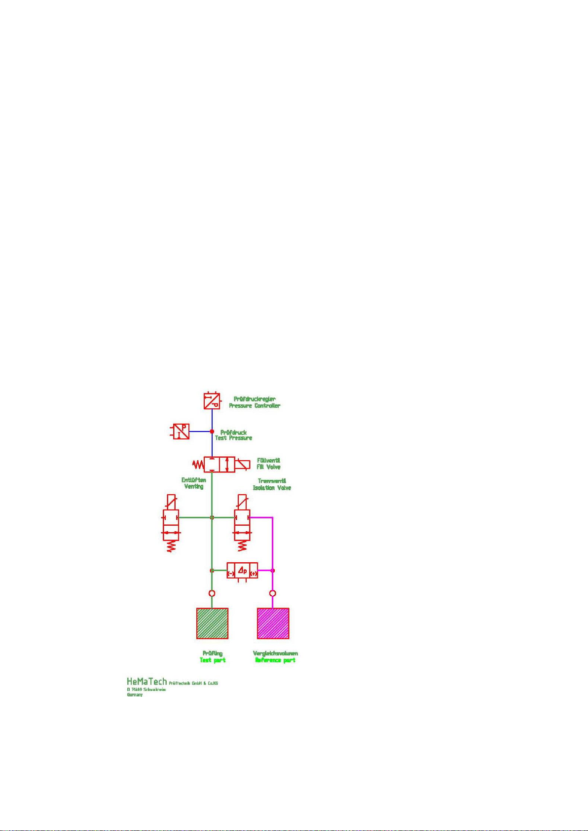
As already indicated by the name differential pressure method, the pressure difference
in the measuring branch caused by a leak in the specimen is compared with the pressure in the blocked off reference branch.
Function schematic of differential pressure test
EN 3925-0060 V207-00 MANUAL R03.doc 15
HeMaTech
Prüftechnik
Page 16
The differential pressure method Product description
16
Pressure
Leak
work piece
Filling
Stabilizing
Venting
Measuring
Test time
leak tight
work piece
Time
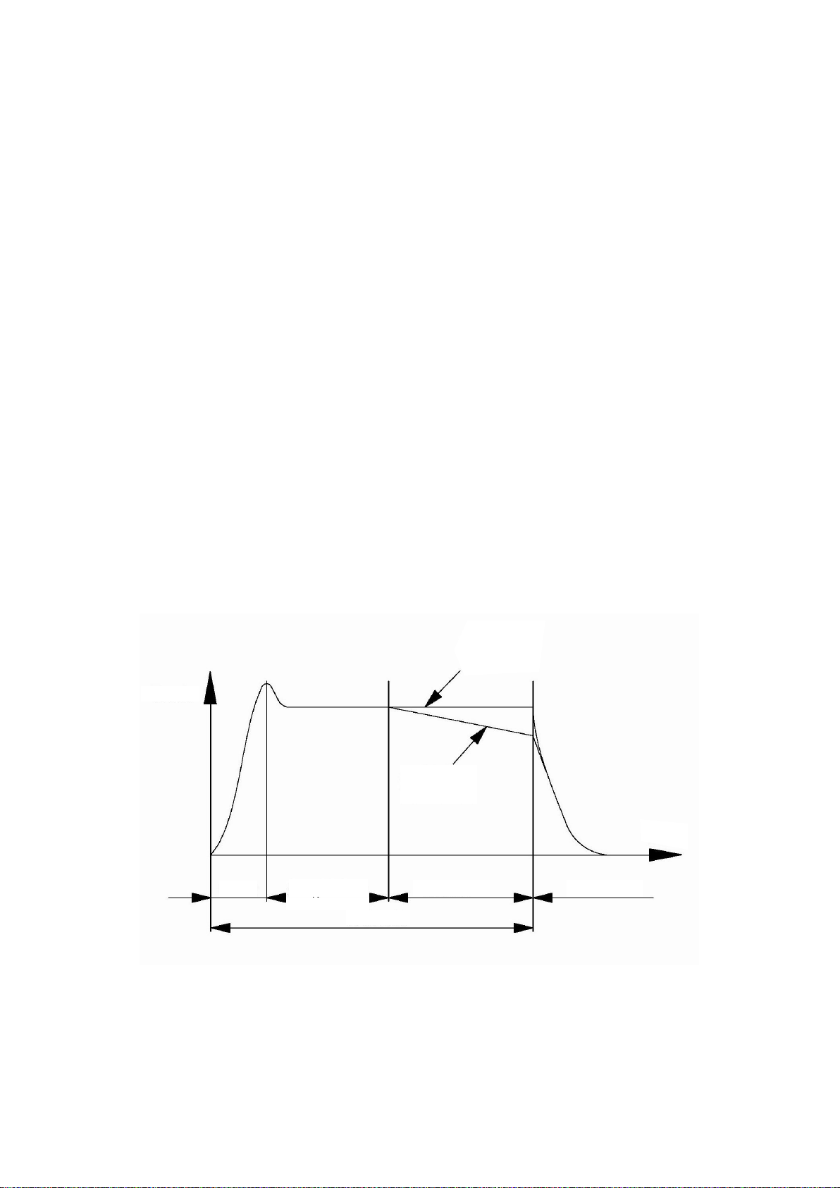
The testing process consists of three phases:
1. Filling
With the filling and isolating valve open, the testing pressure set on the pressure regu-
lator is applied to reference volume, measuring transducer and specimen The filling
time is determined by the performance of the pressure regulator, the total volume of
the facility including testing and reference volume, the piping resistance and the crosssection of the valves.
2. Stabilizing
This is the phase of pressure and temperature stabilization in the entire system. The
reference volume shown in the illustration – one normally uses a pressure tight original
work piece – serves the purpose of creating the highest possible symmetry level between testing and reference circuits. This enables a reduction of stabilization time, because possibly existing interfering influences affect both circuits of the system and thus
reduce the effect on the measuring result. Empirical values reveal that with volumes
< 5000 ccm a reference volume is normally not needed.
3. Measuring
The actual measuring phase starts after the stabilization time has expired. By closing
the filling and isolation valves the measuring and references branches are separated
from each other. If the specimen has a leak, the pressure in the measuring branch will
drop in comparison to the reference branch. The measuring transducer shows the resulting pressure difference in the measuring value display. If the pressure difference exceeds the preset limit value during the measuring phase, a signal
Reject
will be
submitted and the test stopped.
Pressure course in the test system during the test process
EN 3925-0060 V207-00 MANUAL R03.doc
HeMaTech
Prüftechnik
Page 17

Product description The differential pressure method
The isolating valve shown in the illustration is an isolating valve which has been specially developed for leak testers from HeMaTech Prüftechnik. The special requirements
for leak testing were already accounted for in the development of the valve.
Due to the symmetric design, both measuring branches are simultaneously isolated
from each other when closing the valve. Volume and pressure differences therefore act
uniformly on both measuring branches, whereby measuring faults are ruled out. By
distinct separation of both measuring circuits, measuring errors caused by leaks in upstream filling valves are reliably prevented. The isolating valve is pneumatically controlled and heating, caused by e.g. the coil of a solenoid valve, is thus avoided.
Leak testing equipment using the differential pressure method is well established in series production. A vast variety of work pieces and assemblies, ranging from ball-point
cartridges to vehicle engine blocks, are reliably tested for leaks.
EN 3925-0060 V207-00 MANUAL R03.doc 17
HeMaTech
Prüftechnik
Page 18

Performance characteristics Product description
18
Performance characteristics
The test device offers the user a number of functions and possibilities to set parameters
for measurements, as well as for the output and distribution of these measuring results:
Function monitoring
The device takes over the monitoring of parts and function sequence. The user re-
ceives error messages through the plain text display and floating contact.
99 Test programs
There is a possibility to create up to 99 different programs and to select these either
via the control panel, or by means of external signals (BCD, 8 bit) in automatic operation.
Data exchange
All test parameters and measuring results can be entered and output, printed or pro-
cessed further by PC through the serial interface.
Result signals
The device delivers several result signals:
− I.O. (Accept)
− Rework
− Reject and gross leak (gross leak message only through V24 interface)
− Envelope curve,
Filling fault. (optional)
− Fault
The result signals can vary depending on device variant or have different designations.
Fill pressure, underfill pressure, underfill time and test pressure,
are separately set/disabled via keypad for each test program.
Times for fill, stabilization, pause, tare, measure and vent,
are separately adjustable via keypad from 0.1 … 999.9 seconds for each test pro-
gram.
Measuring range
∆ p 0 … 3000 Pa.
Resolution 1 Pa; limit contact setting up to max. 2000 Pa
(100 Pa = 1 mbar = 10 mmWC).
Measuring value display
You can switch over to:
PASCAL, mbar, psi, mmWC, mmHg, ml/min
EN 3925-0060 V207-00 MANUAL R03.doc
HeMaTech
Prüftechnik
Page 19

Product description Design and working principle
Design and working principle
The test device is microprocessor controlled, of modular design and, due to its division
into pneumatic and electronic sections, can be adapted to the most different requirements of customers. The design as a 19 inch plug-in unit (3HE) enables problem free
integration into control cabinets. The device dimensions W × H × D are:
− for standard housing 590 × 165 × 456 mm (3 HE without front door)
− for optional version 590 × 300 × 456 mm (6 HE without front door)
Devices with lockable front door have a depth (D) of 496 mm.
Pneumatics
The pneumatic section of the tester consists of the following main components:
− the pressure control for filling and testing pressure via electronic pressure set-
ting (set up specification by computer) with pressure monitoring by means of
an adjustable tolerance window
− a pneumatically controlled isolating valve, which rules out heating of the valve
− a temperature compensating differential pressure measuring transducer for
testing test volumes up to 5000 ml without reference volume
− a high single-side overload protection (max. 150 bar/g) of the differential
pressure measuring transducer
− an optional leakage simulation with precision needle valve
(flow meter to be connected externally)
− pressure sensors for function monitoring of the pneumatic circuit
See also Pneumatic Diagram in the appendix
Electronics
The electronics section of the tester consists of
− microprocessor system,
− battery buffered RAM memory,
− alpha-numerical membrane keyboard for all input functions,
− On/Off switch integrated in the membrane keyboard,
− key switch to protect against unauthorized changing of test parameters and
− graphics display for device menus and up to 2 serial interfaces
EN 3925-0060 V207-00 MANUAL R03.doc 19
HeMaTech
Prüftechnik
Page 20

Scope of delivery Product description
20
Scope of delivery
1 Leak Tester 3925 - 0050
1 Power cable
1 Counter plug to machine control
2 Key for write protection switch
1 Operating instructions
2 Caps
(for specimen connection and reference volume connection)
Should one of these items be missing or damaged, you should immediately consult
your supplier.
Accessories
EN 3925-0060 V207-00 MANUAL R03.doc
HeMaTech
Prüftechnik
Page 21
Product description View of device
View of device
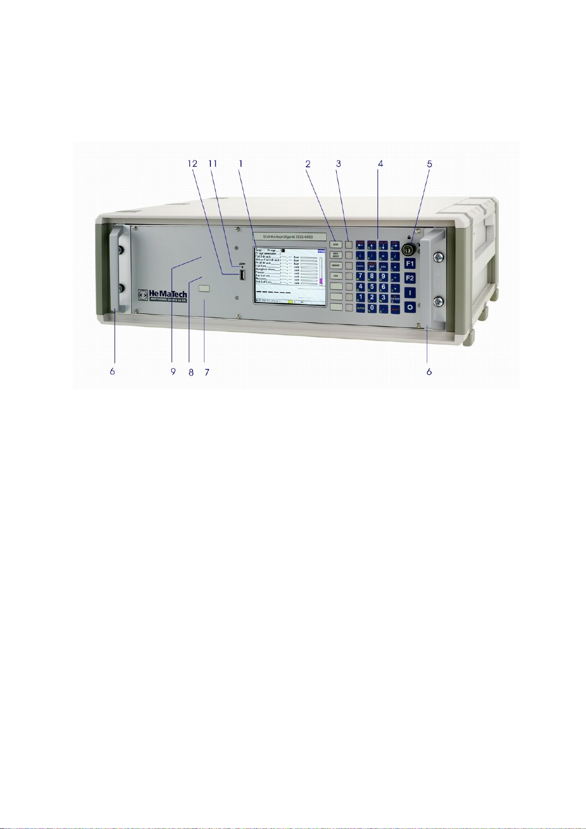
Front view
1 LC-Display
to display the program menus
2 Status fields
4 assigned by default, 3 for individual assignment
3 LED
to show the current test result
4 Alpha-numerical control field
to enter the desired test parameters
5 Write protection switch
to protect against undesired changing of test parameters
6 Handle
for installation and removal of the 19“ plug-in unit
7 Precision needle valve
for leak simulation (option)
8 Connection socket
for leak display (option) in pressure increase measurement to the outlet of a flow
meter
9 Connection socket
for leak display (option) in pressure increase measurement to the inlet of a flow meter
10
11 LED
to show the working status of the USB interface
12 USB interface
EN 3925-0060 V207-00 MANUAL R03.doc 21
HeMaTech
Prüftechnik
Page 22
View of device Product description
22
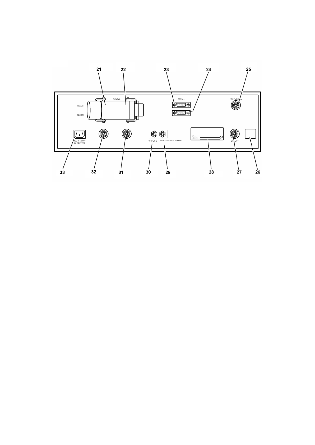
Back view
21 7-pin Sub-D socket, digital OUT, X20
22 37-pin Sub-D plug, digital IN, X21
23 9-pin Sub-D socket, serial, V24 RS232C Ser#1, X22
24 9-pin Sub-D socket, serial, V24 RS232C or Profibus Ser#2, X23 (option)
25 Connection for test medium (option)
26 Table with pressure values for supply air and test media
27 Supply air connection, maximum 10 bar/ü, oil free and filtered
28 Type plate
29 Connection for reference volume (pressure proof original specimen)
30 Connection for specimen
31 Air relief outlet for silencer
32 Special connection see pneumatic diagram (option)
33 Power supply socket 100 … 240 V, 50 … 60 Hz,
with fuse T 2.0 A
EN 3925-0060 V207-00 MANUAL R03.doc
HeMaTech
Prüftechnik
Page 23
Product description Control elements
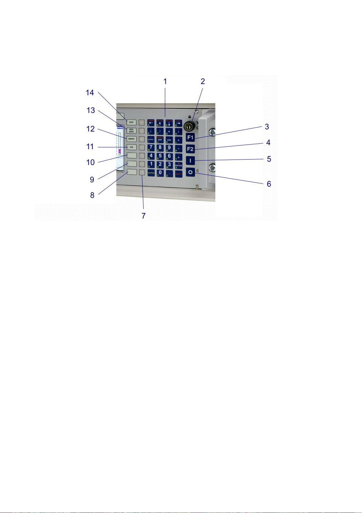
Control elements
1 Alpha-numerical control field
to enter test parameters (see next page)
2 Key switch
to enable and disable the write protection
3 Key F1
function key (output of filling curve measuring data)
4 Key F2
to enable device functions and to start the test sequence
5 Key I
to switch ON the device
6 Key 0
to switch OFF the device
7 LED´s
to show the current test result
8 free status field
9 free status field
10 free status field
11 Status field LEAK
if the LED next to this status field lights up, the leak simulation is active
12 Status field REJECT
if the LED next to this status field lights up, the current specimen is leaking
13 Status field REWORK
if the LED next to this status field lights up, the current specimen is leaking, but can
be reworked
14 Status field I.O.
if the LED next to this status field lights up, the current specimen is with out leak
EN 3925-0060 V207-00 MANUAL R03.doc 23
HeMaTech
Prüftechnik
Page 24

Control elements Product description
24
Control Keys in the alpha-numerical control panel
ALPHA
The text input can be activated and deactivated by pressing the ALPHA-key. When
the red LED ALPHA lights up, the numerical keypad is not activated. For the input of
numerical values you must first activate the numerical keypad.
SHIFT
With the SHIFT-key you can enable the input of capital letters and activate the red
key functions. You must always press the SHIFT-key first, before entering a new character.
ENTER
By pressing the ENTER-key you can confirm a previously made input or selection.
Arrow Keys
With the arrow keys in the top row of the keypad you can move the marking in the dis-
play to the desired position, i.e. you can control the cursor.
ESC
By pressing the ESC-key you can abort a process that had been started and return to
the previous menu.
PgUp
By pressing the keys SHIFT + PgUp you can scroll one page back.
PgDn
By pressing the keys SHIFT + PgDn you can scroll one page forward.
EN 3925-0060 V207-00 MANUAL R03.doc
HeMaTech
Prüftechnik
Page 25

Connecting peripheral equipment Installation and start-up
25
ATTENTION!
Choose an installation location, at which the device is neither exposed to extreme temperatures, nor to extreme humidity. The ambient
temperature must be in the range from 0 to 50 °C, the relative humidity must not exceed 90 % and no condensation should occur.
DANGER caused by electric current!
Separate the device from the electric power supply before connecting
device components.
NOTE!
Warranty claims will not be accepted if the tester is damaged by oil
and/or water entering into the unit.
Installation and start-up
The installation measures described in this manual must only be carried out by trained
specialists. The applicable regulations for electrical engineering must in any case be
observed and complied with.
Preparations
The device must stand in a firm position, protected against vibration.
Avoid a location near heating or air conditioning systems.
Make sure that the supply voltage matches the supply voltage specified on the type plate.
Only install the device inside a control cabinet, if adequate ventilation is assured.
Position the device as close as possible to the specimen, in order to maintain the test
circuit volume at a low level and to achieve more accurate measuring results.
Keep a space of approx. 100 mm behind the back of the unit for electric cables,
pneumatic hoses and connecting plugs.
Connecting peripheral equipment
Before you can start up the tester, the following connections must first be made:
to the compressed air supply, optionally to the test medium, to specimen and reference volume, to the machine control, to the data output through a serial interface and
to the power supply. Only then is the leak tester ready for operation.
Before connecting compressed air/test medium
In case of major pressure fluctuations in the compressed air supply network we rec-
ommend the installation of a pressure switch, which will emit an electrical output signal when the pressure drops. This signal can be used for display/machine shut-down
purposes. Install a filter unit (min 1µm) in the supply line at a safe and well visible location, to ensure the supply of dry, oil free compressed air. Check the service unit at
regular intervals to prevent the device from being soiled by oil. Include the inspection
and changing of filter cartridges in the maintenance plan; this applies also for filters
with automatic condensate drainage.
EN 3925-0060 V207-00 MANUAL R03.doc
HeMAaTech
Prüftechnik
Page 26

Connecting peripheral equipment Installation and start-up
26
Connecting compressed air
The supply air connection, for supplying the leak tester with compressed air, is located
on the back of the device. The supply air connection has a G¼" fitting for a 8/6 mm
hose.
The supplied compressed air must be oil free and filtered. Please make sure that the
compressed air to be connected has a constant pressure of approx. 1.5 bar above the
filling or testing pressure (min. 5.0 bar/ü, max. 10 bar/ü, see also pressure table on
back of housing).
Before connecting the air supply make sure, that the compressed air hose is undamaged and will not be kinked or squashed. The hose must be not pressurized free.
After connecting the hose, tighten the spigot nut of the fitting and check for tight fit.
Connecting the test medium (option)
Devices with a test pressure higher than 6 bar are equipped with a separate connec-
tion for the test medium . This also applies for devices, which are to be operated with
a special test medium, such as nitrogen, helium, etc.
The source pressure value can be taken from the table of pressure values on the back
of the device. Before connecting the test medium supply make sure that the hose for
the test medium is undamaged and will not be kinked or squashed. The hose must be
not pressurized.
After connecting the hose, tighten the spigot nut of the fitting and check for tight fit.
Connecting specimen and reference volume
Two fittings G1/8" for 8/6 mm hoses for connection of a specimen and a reference
volume are arranged on the back of the tester. The dimensions of the hose connections may vary in dependence on the version of the device (test volume).
In order to prevent any expansion (breathing), the hose should be of appropriate
strength. A suitable hose (PA-tube) is available from us.
Hose 4/2; max. 45 bar at 20 °C; Order-No. 8082-0354
Hose 6/4; max. 27 bar at 20 °C; Order-No. 8082-0379
Hose 8/6; max. 19 bar at 20 °C; Order-No. 8082-0381
Hose 10/8; max. 15 bar at 20 °C; Order-No. 8082-0382
Make sure that the supply lines to specimen and reference volume are pressure tight.
The lines must be as short as possible. Avoid the use of plug-type fittings, because these could cause leakages in the testing circuit.
If possible, use a pressure tight original specimen as reference volume. With a test
volume < 5 000 ml the connection of a reference volume is not necessary. For thinwalled or elastic specimen the connection of a reference volume may be necessary,
even for small volumes. If you do not connect a reference volume, you must close the
reference volume connection with the blind cap provided for this purpose.
Before connecting the reference volume make sure that the hoses for test medium and
reference volume are undamaged and will not be kinked or squashed.
The hoses should not be pressurized.
EN 3925-0060 V207-00 MANUAL R03.doc
HeMaTech
Prüftechnik
Page 27
Installation and start-up Connecting peripheral equipment
27
NOTE!
If you do not connect a reference volume, you must close the reference volume connection with the blind cap provided for this purpose.
After connecting the hose to the specimen connection, tighten the spigot nut of the fitting and check for tight fit.
After connecting the hose, tighten the spigot nut of the fitting and check for tight fit.
If necessary plug the hose to the reference volume connection, tighten the spigot nut
of the fitting and check for tight fit.
Connecting the machine control
There are several possibilities for communication between tester and machine control:
1. Parallel interface
− the 37-pin Sub-D socket, digital OUT,
X20 (position number 11, on back), for output signals
− the 37-pin Sub-D socket, digital IN,
X21 (position number 12, on back), for input signals
Wire the plugs first according to the
Provide a suppressor circuit
plug assignment diagram
in the
appendix
.
(g.g. varistor or diode) for all output signals, in order to avoid interferences.
The tester requires a pulse of at least 0.5 second. The outputs need approx. 5 mA, the
outputs can be loaded with max. 0.5 A (max. 30 VDC).
Once all preparations have been made:
Connect all plugs and ensure tight fit.
The modes of input and output signals can be found in the enclosed flow chart.
2. Serial interface.
2.1 Serial interface with register programming format
(see menu 3. SETUP PARAMETER command reference - remote control
via serial interface).
2.2 Serial interface with Profibus format
(see menu 3. SETUP PARAMETER command reference - Profibus output
format).
EN 3925-0060 V207-00 MANUAL R03.doc
HeMaTech
Prüftechnik
Page 28

Switching the device ON and OFF Installation and start-up
28
DANGER caused by electric current!
After connecting the device check that all cables are routed in such a
way, that they cannot be buckled or squashed or damaged in any
other way.
Connecting serial interface(s)
After completing the test, the up-to-dated measuring values can be output to a data
terminal unit via the serial interfaces. The
sample printouts
. The header appears on each new page. When switching the device
Appendix
to these instructions contains a few
off and on again, the successive number is automatically reset to 1.
The test parameters for the existing programs can be output in the menu
SET PARAMETER (see 1.1 Data output Parameter).
The two serial interfaces of the device are:
− 9-pin Sub-D socket, serial, V24 RS232C Ser#1, X22
(see item 23 back view)
− 9-pin Sub-D socket, serial, V24 RS232C or Profibus Ser#2, X23
(see item 24 back view)
Wire the plug connections by following the enclosed
plug assignment diagram
.
Transfer format: (factory setting)
115.200 baud, baud rate adjustable from 300 … 460 800,
8 bit data, 1 stop bit, no parity, no protocol
Connecting the electric power supply
Connect the leak tester only to a main voltage of 100 … 240 V, 50/60 Hz (without
changeover) provided for this purpose.
The power consumption of the device is approx. 100 VA.
It is protected by a T2A / 250V IEC127-2 input fuse.
Plug the power supply cable into the mains connection on the back of the unit.
Connect the power supply cable to the mains supply network.
The tester is ready for operation and can be switched ON.
Switching the device ON and OFF
Only switch on the device after all connections have been made and checked for correct fit.
Press key I on the front of the device to switch on.
The display light is switched on.
Press key 0 on the front of the device to switch off.
The display light is switched off.
EN 3925-0060 V207-00 MANUAL R03.doc
HeMaTech
Prüftechnik
Page 29

Switching the device ON and OFF Initializing
Initializing
Before starting operation all connections to peripheral equipment must be made and
checked for tight fit.
Switch on all peripheral equipment by following the corresponding instructions.
Switch on the tester, see previous section.
The display is switched on and the device is initialized.
Dialog window during initialization of the device
Dialog window during initalization of the device with option Profibus
Test devices with activated Profibus interface try to make a connection to the Profi-
bus during the initialization.
The attempt to connect is indicated in the help bar.
No connection to the Profibus leads to the message “connection failed” inticated
in the help bar.
By pressing the key “ESC” the failed connection is acknowledged and the main
menu is displayed.
EN 3925-0060 V207-00 MANUAL R03.doc 29
HeMaTech
Prüftechnik
Page 30
Switching the device ON and OFF The display
30
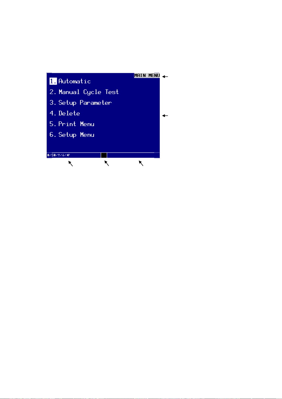
Title/menu bar
Main window with
sub-menus or menu
options
Help bar
Command bar
Keyboard Shift
The display
Wait until the initialization has been completed and the MAIN MENU appears in
the display.
The main menu appears after the device has been initialized.
Title or menu bar
The name of the current dialog window or application always appears in the top right
hand corner of the display.
Main window
In the main menu you will find the individual selectable sub-menus.
Command bar
The command bar shows the available keys to operate the current menu:
# for alpha-numerical input
to move the cursor up
to move the cursor down
to move the cursor to the left
to move the cursor to the right
to confirm an input or a selection by pressing the ENTER-key
ESC to abort an action/to return to the previous menu
PgUp to scroll on page back
PgDn to scroll one page forward
F1 function key
F2 to start/enable a certain system function
Key symbol Operate the key switch
EN 3925-0060 V207-00 MANUAL R03.doc
HeMaTech
Prüftechnik
Page 31

The display Working with the program
31
NOTE!
If you leave a dialog window in input mode, all entries previously
made in the dialog will be lost.
Keyboard Shift
The Keyboard Shift displays the selected input mode.
blank = numeric input
A = alphabetic input
S = Shift activates the red marked key board functions.
SA = capital letters.
Help bar
The help bar contains information about the selected process. When the cursor is in
an input field, the info bar will show a brief
description of the command or the possible input.
Working with the program
The device is interactively operated by means of a menu system, which always ends in
a dialog window. The name of the current dialog window appears in inverted characters (white on black) in the title bar at the top right of the dialog window. The keys,
which can be used for operation, are listed in the command bar at the bottom left. In
the help bar at the bottom right you will find information to the possible entries for the
parameter, on which the cursor is presently positioned.
You can select a menu option by either moving the cursor with the arrow keys, or by
direct input of the cipher in front of the menu. Then confirm the selection by pressing
the ENTER-key.
The program memorizes the settings made last in each dialog window. When you call
up a dialog window again later, the cursor will be at the position that was changed last.
Using the write protection switch
The possible input in a dialog window depends on the position of the write protection
switch on the tester. If the key switch is in vertical position or is pulled off, the device is
in write protected viewing mode and you can only make a few changes concerning the
selection and appearance of saved data.
When you turn the key to the right, you switch on the input mode, and you can change
saved data or enter new data. In input mode the cursor jumps to the position that was
changed last in the displayed dialog window.
You can always close a dialog window by pressing the ESC-key.
If you have changed data in one of the dialog windows in input mode and turn the
write protection switch to the left, i.e. locking, these data in the dialog window will be
saved. The device acknowledges this saving process with a short audible signal.
Faulty or incorrectly entered data are automatically corrected by the program or replaced by standard parameters specified in the system configuration. In such a case
the user is informed about the changed or replaced data by a warning window.
EN 3925-0060 V207-00 MANUAL R03.doc
HeMaTech
Prüftechnik
Page 32

Program structure Command reference
32
Level 1
Level 2
Level 3
Level 4
Main menu
1. Automatic
2. Manual
1. Test
2. Pressurize
(Flooding)
3. Setup
1. Parameter set
2. Date & Time
3. Serial Port(s) )
1. Serial #1
2. Serial #2 (option) or Profibus
3. USB-Stick (option)
4. Sequencer
4. Delete
5. Print Menu
1. View program status 2. Data collection
3. Operating data
4. Counter
5. Backup
6. Error counter status
7. Record)
8 Record Reference
6. Settings
1. Display
2. System parameters
3. Pressure control
4. System status
5. Options
Command reference
In this chapter you will find all commands and functions of the control software for the
leak tester Leak Test 0050. The sequence follows the program structure, as shown in
the table:
Program structure
After you have started the device and the initialization process is completed, the display will show the MAIN MENU of the program or, if applicable, the previously set
start menu.
EN 3925-0060 V207-00 MANUAL R03.doc
HeMaTech
Prüftechnik
Page 33
Command reference Menu 1. AUTOMATIC
33
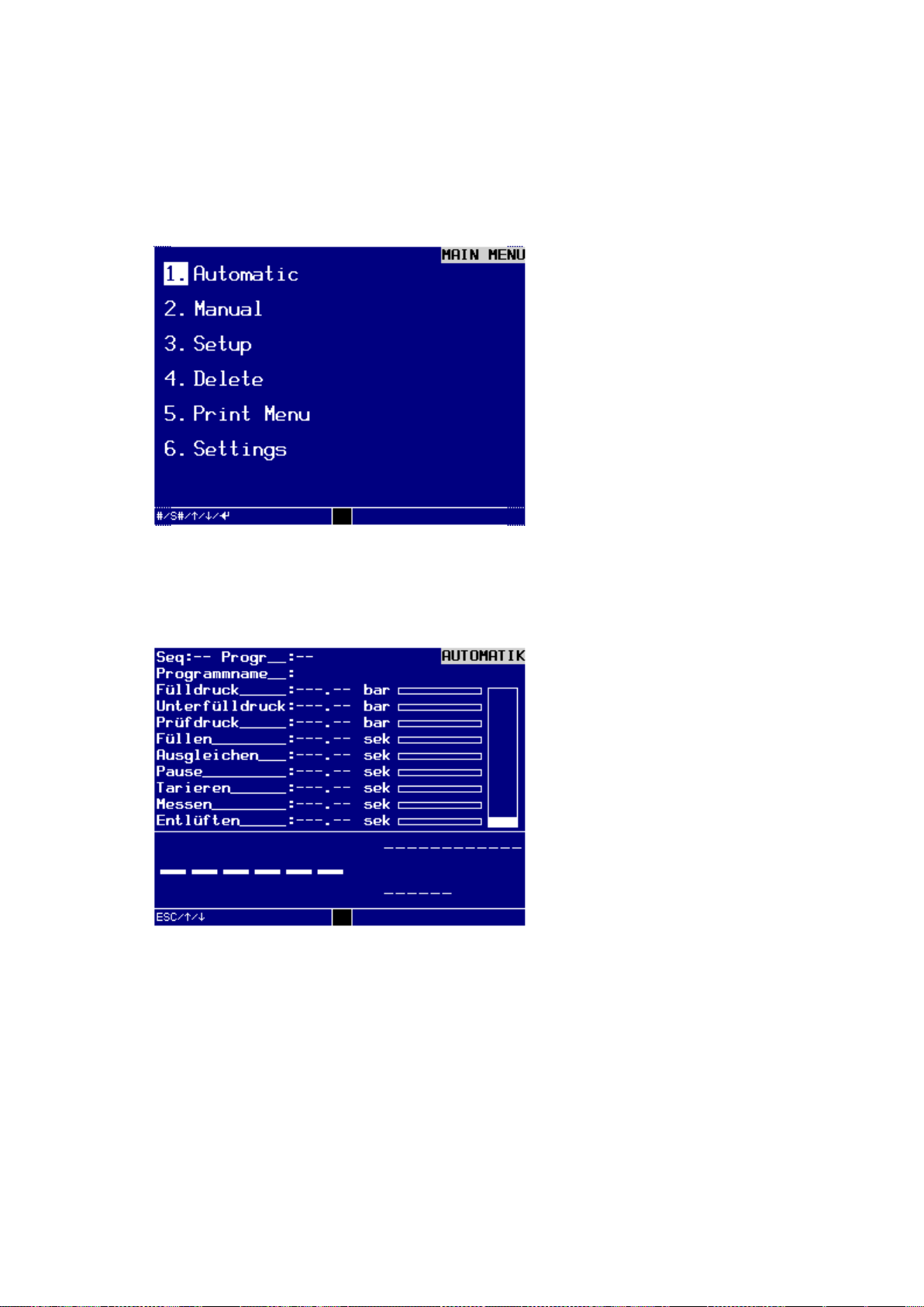
Menu 1. AUTOMATIC
In AUTOMATIC mode the device is entirely controlled via the interface for machine
control. This menu can only be used to monitor the sequence.
Dialog window MAIN MENU
Move the cursor to the first menu option 1. Automatic.
Press the ENTER-key on the control panel.
The display shows the sub-menu AUTOMATIC.
Dialog window AUTOMATIC
EN 3925-0060 V207-00 MANUAL R03.doc
HeMaTech
Prüftechnik
Page 34
Menu 1. AUTOMATIC Command reference
34
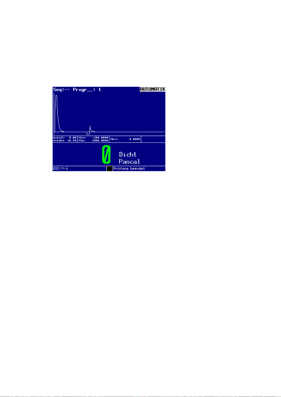
Display the filling curve
In this mode you can toggle between the previous display and the filling curve display
by simply pressing the arrow keys.
Press the SHIFT-key and any arrow key on the control panel.
The filling curve display appears on the screen.
Filling curve display window
Press the ESC-key on the control panel to return to the MAIN MENU.
EN 3925-0060 V207-00 MANUAL R03.doc
HeMaTech
Prüftechnik
Page 35
Command reference Menu 1. AUTOMATIC
35
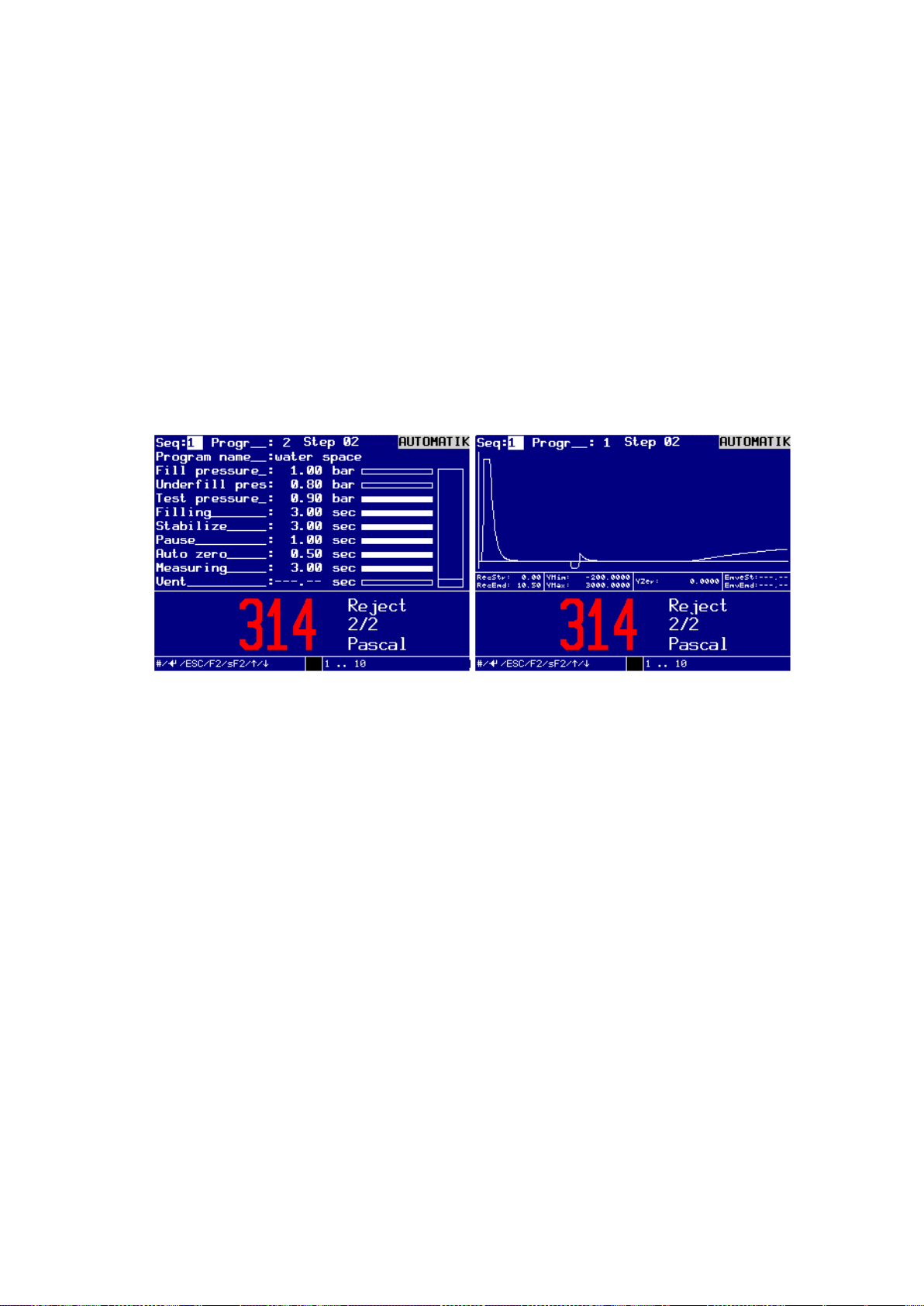
Sequencer
The sequencer function can be globally activated or deactivated.
(see sequencer setup)
With the sequencer activated, the transmitted program number is interpreted as Se-
quencer Number. The transmitted program number must only be in the range from 1
to 10. Otherwise an error message 3 (Program not available) will be submitted.
With the Start signal the steps memorized under the selected sequencer number are
successively processed.
Besides the program number the dialog window Automatic also shows the sequencer
number Seq: -- and the active step Step: --.
With the sequencer activated the number of passed cycles and the total number of cycles are displayed in between the measuring result and the measuring value unit.
Dialog window AUTOMATIC SEQUENCER
If an error occurs in the sequence, the output error will be set and the complete test
sequence aborted. The error must be acknowledged as specified for the corresponding
machine interface. After a restart the complete test sequence is repeated.
If the input Abort is set, the entire test sequence will also be aborted. A restart will thus
also start with the first activated test step.
In dependence on the setting of the switch NIO=continue for the corresponding test step,
the sequence is aborted or continued in case of a measuring result unequal I.O..
At the end of any test step the output of the corresponding test result is set for a short
time.
If none of the 10 possible steps is activated in the selected sequencer, the error message no step activated with error number 40 will be generated.
EN 3925-0060 V207-00 MANUAL R03.doc
HeMaTech
Prüftechnik
Page 36

Menu 1. AUTOMATIC Command reference
36
Automatic mode without leak simulation
In automatic mode the device is operated through a machine control interface. For
more details please refer to chapter
Exchange of signals with the machine control
.
Automatic mode with leak simulation (option)
In addition to the operation described in section SETUP/Test Program you must ap-
ply the signal Leak to X21/3 from the machine control, before the signal Machine
ready is applied.
Automatic mode static test (flooding)
If the signal Static Test X21/4 is applied instead of the signal Start X21/2, the speci-
men will be exposed to the test pressure determined in the parameter set of the selected program. The specimen is kept pressurized, as long as the signal Static Test is
applied.
EN 3925-0060 V207-00 MANUAL R03.doc
HeMaTech
Prüftechnik
Page 37
Command reference Menu 2. MANUAL
37
NOTE!
If you selected the option EnvelopCurveTolerances ON in the dialog
window SETUP TEST PARAMETER SET, the error message
REFERENCE CURVE MISSING will be displayed when starting the first
test.
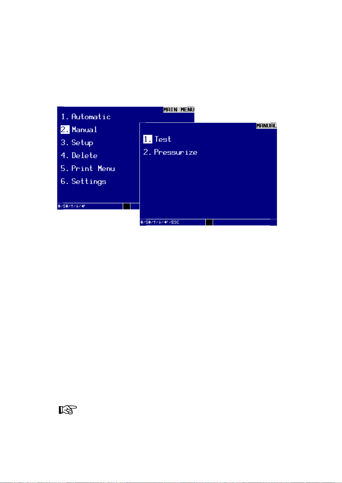
Menu 2. MANUAL
The menu 2. MANUAL serves the manual operation of the test device. All commands
must be entered manually via the keypad.
Choose MAIN MENU / 2. Manual the MANUAL MENU is displayed. There are two
sub-menus available:
Dialog window MANUAL MENU
− Test.
You can check manually with and without leak.
− Pressurize (flooding).
You can pressurize the specimen manually with test pressure.
1. Test
Confirm the selection 1. Test by pressing the ENTER-key or 1, an empty dialog window
MANUAL will be displayed.
To launch the desired program:
enter the number of the desired program (in this example: 1) into the top line and
confirm the entry with the ENTER-key.
Testing without or, optionally, with leak simulation
The dialog window MANUAL gives you the possibility to start a test without or, option-
ally, with leak simulation.
Press key F2 to start the test without leak simulation.
or
Press the keys SHIFT and F2 to start the test with leak simulation.
EN 3925-0060 V207-00 MANUAL R03.doc
HeMaTech
Prüftechnik
Page 38
Menu 2. MANUAL Command reference
38
For the initial testing of the device functions you should temporarily disable this option.
The reference curve determination function is described later.
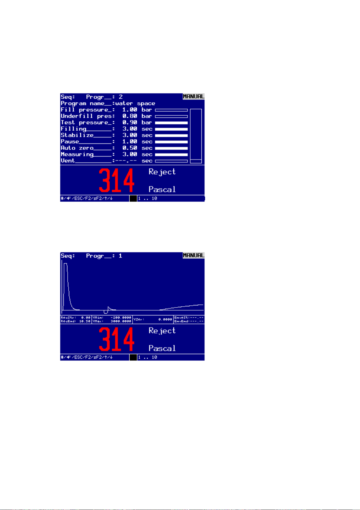
The test sequence can be easily followed by the horizontal progress bar. The current
status of the test sequence is additionally displayed in the help bar.
Dialog window for manual testing
If you prefer the filling curve display:
Press the SHIFT–key and any arrow key.
The display shows the test sequence in form of a curve.
Dialog window for filling curve representation of test
If you want to return to the dialog window, press SHIFT–key and a arrow key
again.
You can now exit the menu by pressing the ESC-key and call up and execute other
functions of the device, without having to interrupt the test process. The test sequence
is not interrupted, but continues in the background. The test result is displayed after the
test sequence has finished.
If you want to abort the test:
press the keys SHIFT + ESC in succession.
The test sequence is aborted, the up-to-date status of the test at the time of the
abortion remains in the display.
EN 3925-0060 V207-00 MANUAL R03.doc
HeMaTech
Prüftechnik
Page 39
Command reference Menu 2. MANUAL
39
1.1 Determination of a reference record
Connect a leak free original work piece to the tester.
Proceed as follows to determine the reference curve:
enter the number of the desired program (in this example: 1) into the top line and
confirm the entry with the ENTER-key.
Turn the key switch clockwise to horizontal position (input mode ON).
Press key F2 to start the test without leak simulation.
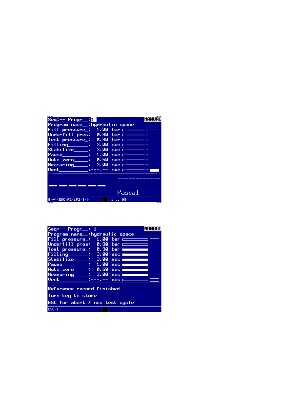
You can follow the test sequence by the horizontal progress bar, the help bar additionally shows the corresponding actual status of the test sequence.
Dialog window for manual testing
Once the test is completed, the display will show the following message.
Dialog window manual test, determination of reference curve
Turn the key switch anti-clockwise to vertical position to save the reference curve
you have determined. An audible signal will sound and the determined data will
be written to the RAM memory.
Press ESC to determine a new reference curve.
A new measurement will be executed.
EN 3925-0060 V207-00 MANUAL R03.doc
HeMaTech
Prüftechnik
Page 40
Menu 2. MANUAL Command reference
40
1.1 Sequencer
The sequencer is available in automatic mode and in manual mode.
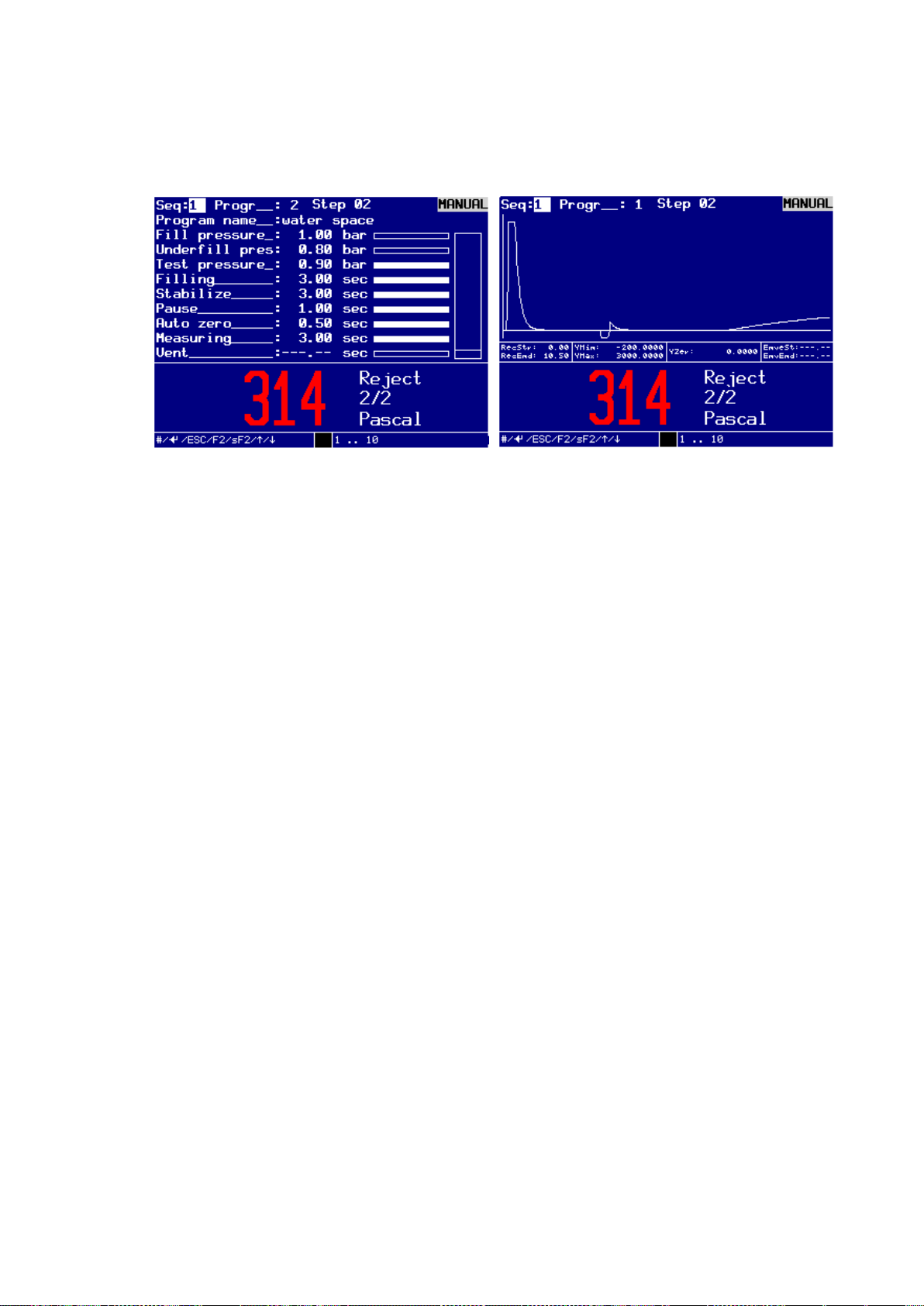
Dialog window MANUAL SEQUENCER
The number of the sequencer is always visible. There is a combined design used for
sequencer number, program number and step number (Seq: -- / Progr: -- / Step: --).
Operating mode:
Sequencer deactivated:
The Sequence number is disabled and displayed as Seq: --.
Automatic mode:
The input field Seq: -- and Progr: -- are not editable.
Manual mode:
The input field Seq: - is not editable. The input field Progr: -- is, as long as no
test cycle was launched, editable. The input area is with 1 ... 99 indicated.
If the entry is completed with Enter, if available, the related test program will
be loaded and the parameters are presented at the display.
Afterwards the test sequence can be started with F2 or Shift + F2.
It is not necessary to enter the program number by pressing the Enter-key.
You can also enter the program number key F2 or Shift + F2. In this case, the
related test program will be loaded and the parameters are presented directly
at the display and directly afterwards test sequence starts.
Sequencer enabled:
The input field Seq: -- shows the Sequence number.
The input field Progr: - is not editable.
Automatic mode:
The input fields Seq: -- and Progr -- are not editable.
If the sequencer program is not available or if no test program is activated in the sequencer program, the input is not accepted and all variable image contents are set to
undefined.
If an error occurs in the sequence, the output error will be set and the complete test
sequence aborted. The error must be acknowledged as specified for the corresponding
machine interface. After a restart the complete test sequence is repeated.
EN 3925-0060 V207-00 MANUAL R03.doc
HeMaTech
Prüftechnik
Page 41

Command reference Menu 2. MANUAL
41
If the input Abort is set, the entire test sequence will also be aborted. A restart will thus
also start with the first activated test step.
In dependence on the setting of the switch NIO=continue for the corresponding test step,
the sequence is aborted or continued in case of a measuring result unequal I.O..
At the end of any test step the output of the corresponding test result is set for a short
time.
If none of the 10 possible steps is activated in the selected sequencer, the error message no step activated with error number 40 will be generated.
EN 3925-0060 V207-00 MANUAL R03.doc
HeMaTech
Prüftechnik
Page 42
Menu 2. MANUAL Command reference
42
2. Pressurize (Flooding)
This function is intended for visual leakage detection, for which the specimen is manu-
ally pressurized with the programmed test pressure.
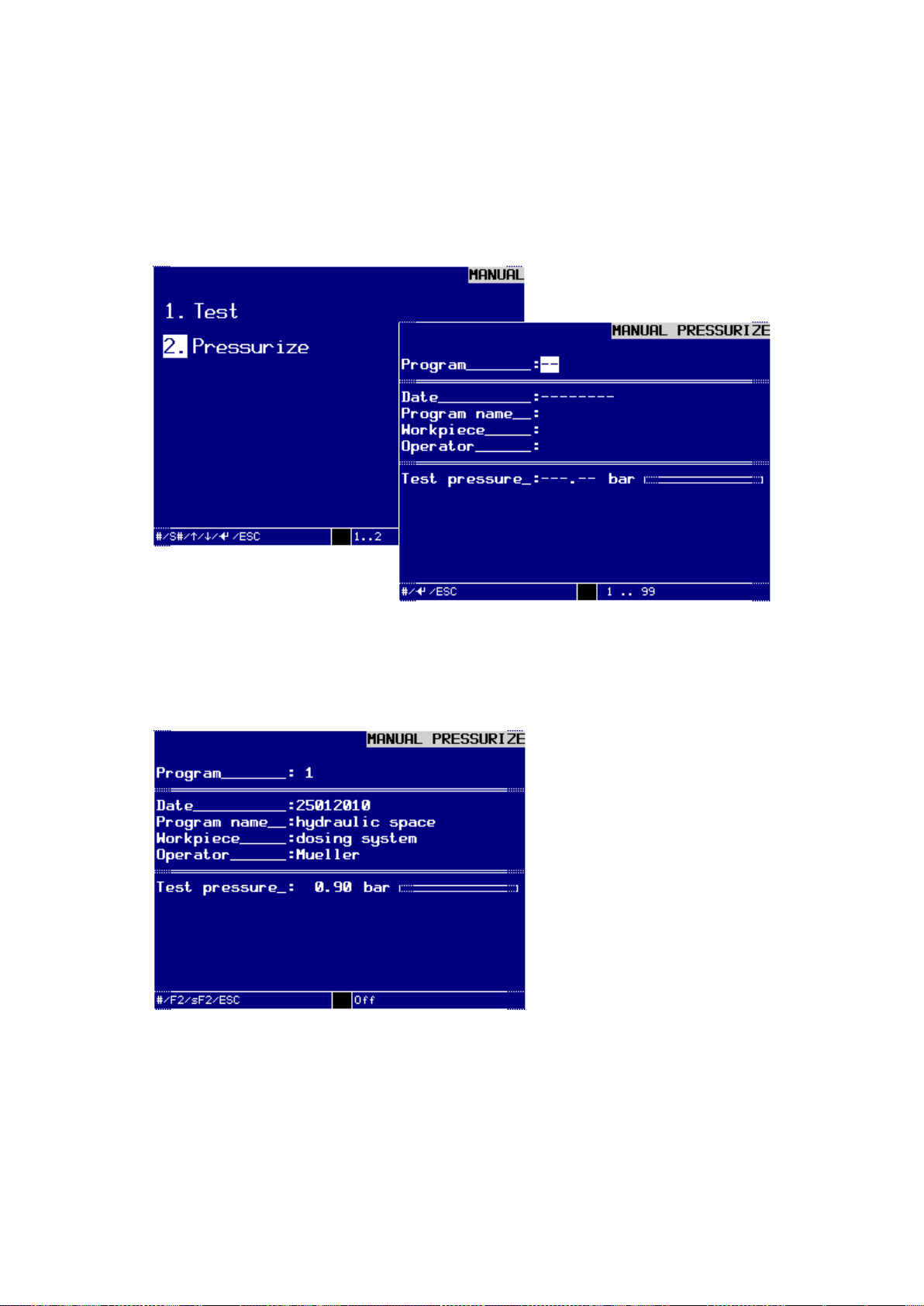
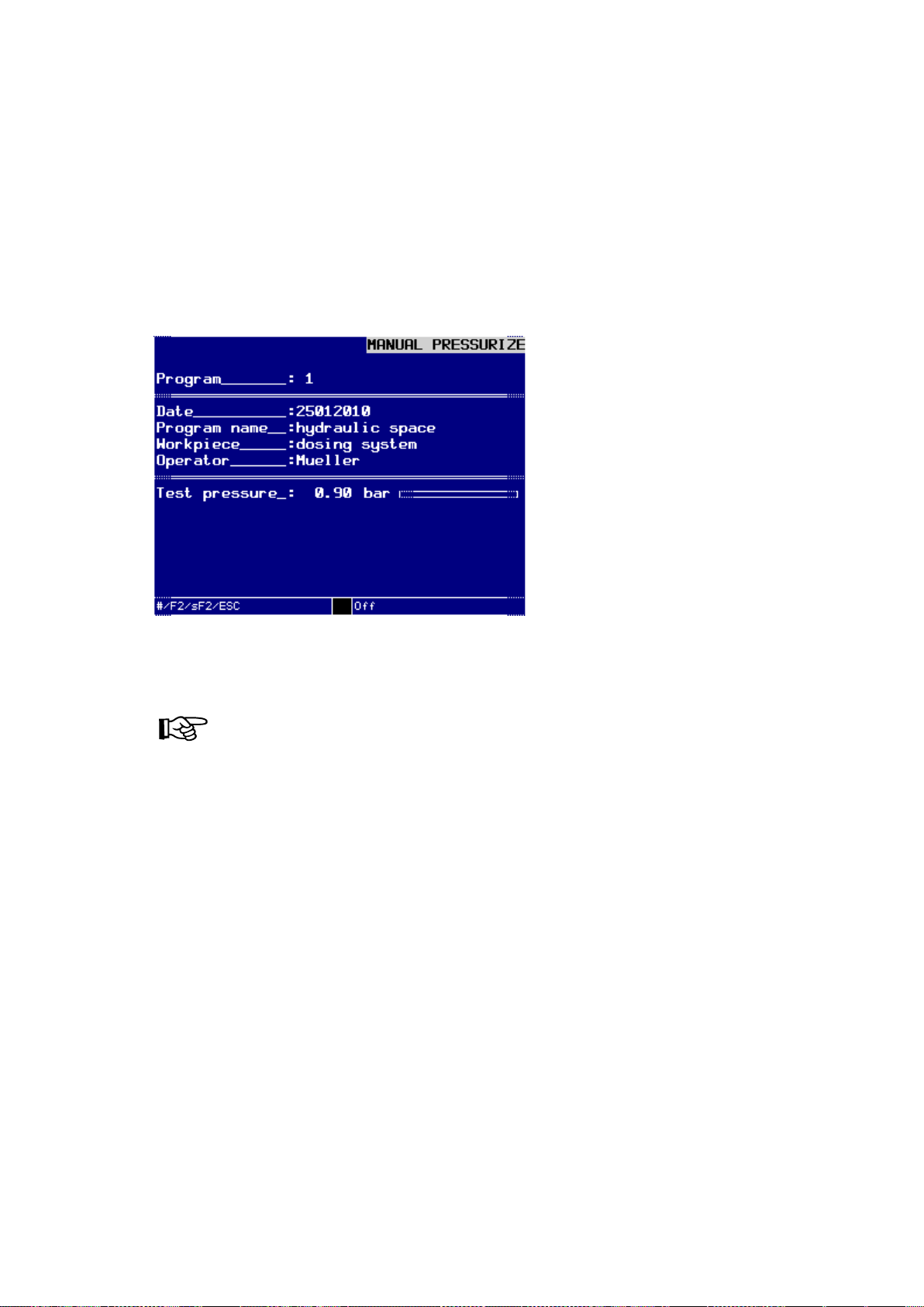
The menu sequence 2. MANUAL/2. Pressurize opens the dialog window MANUAL
PRESSURIZE:
Dialog window for manual pressurize
Into the test field Program: enter the desired number and press the ENTER-key to
confirm.
The dialog window with the desired program is displayed. You can check the programmed test pressure build-up by the horizontal progress bar.
Dialog window for manual pressurize
EN 3925-0060 V207-00 MANUAL R03.doc
HeMaTech
Prüftechnik
Page 43
Command reference Menu 2. MANUAL
43
NOTE!
In the operation modes for automatic and semi-automatic testing, the
duration of pressurizing is determined by application of the signal
PRESSURIZE ON.
Testing without or (optionally) with leak simulation
The dialog window MANUAL PRESSURIZE gives you the possibility to pressurize
the test specimen without or, optionally with leak simulation.
Press key F2 to start pressurize without leak simulation.
or
Press the keys SHIFT and F2 simultaneously to pressurize the test specimen with
leak simulation.
Dialog window MANUAL PRESSURIZE
You can follow the pressure build-up sequence by the horizontal progress bar, the
help bar additionally shows the corresponding actual status of static test.
EN 3925-0060 V207-00 MANUAL R03.doc
HeMaTech
Prüftechnik
Page 44
Menu 3. SETUP Command reference
44
Menu 3. SETUP
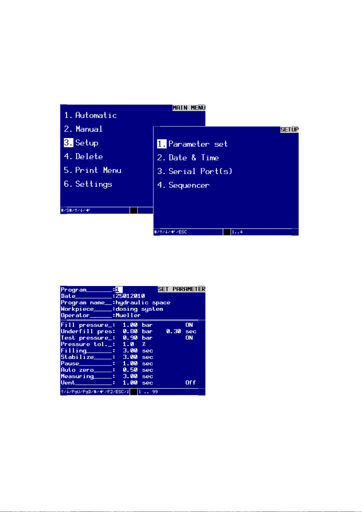
In the MAIN MENU under 3. SETUP you find the dialog window SETUP. This menu
ca be used to set up test programs, set date and time and set up the various interfaces.
Dialog window SETUP
1. Set parameter (Test program)
If you confirm the selection 1. Parameter set in the dialog window SETUP by pressing
the ENTER-key, the following dialog window will open:
Dialog window SET PARAMETER
EN 3925-0060 V207-00 MANUAL R03.doc
HeMaTech
Prüftechnik
Page 45

Command reference Menu 3. SETUP
45
NOTE!
If you want to create a new program, please enter a program number
that is not yet occupied.
If you want to edit a program that already exists, enter the corresponding number.
ATTENTION!
With a pressure/vacuum unit do not enter a fill/test pressure of –
0.09 … 0.19 bar/ü.
NOTE!
Calculate the underfill pressure as in the following example:
Fill pressure F = 2.10 bar/ü
Test pressure P = 1.90 bar/ü
Underfill pressure = P – (F – P) = 1.90 – (2.10 - 1.90) = 1.70 bar/ü
Creating or changing a test program
In order to be able to make entries in this dialog window, you must first switch the de-
vice to edit mode with the key switch:
Turn key switch clockwise.
Write protection is disabled, entries can be made.
Make all following entries and confirm these individually by pressing the ENTER-
key. The help text depends on the version of the device.
The insertion point jumps to the next field.
Program:
Enter a number between 1 … 99.
Program name:
maximum 23 characters (available)
Work piece:
maximum 23 characters (available)
Operator:
maximum 23 characters (available)
Fill pressure:
You may enter a value between 0.2 … 6.00 bar, or accept the default value of
1.00 bar.
Fill pressure ON/OFF
You can switch the filling pressure to ON or OFF with the – and + keys. The default
setting is ON.
Underfill pressure:
You can enter a value between 0.2 … 6.00 bar or accept the default value of
0.80 bar.
EN 3925-0060 V207-00 MANUAL R03.doc
HeMaTech
Prüftechnik
Page 46

Menu 3. SETUP Command reference
46
NOTE!
Change the default values for underfill time, pause time and tare time
only after consulting the manufacturer.
Underfill time: 0.3 s, Pause time: 1.0 s and Tare time: 0.5 s.
Set the times so, that an open specimen connection will cause a rapid shut-down.
ATTENTION!
With a pressure/vacuum unit do not enter a fill/test pressure of –
0.09 … 0.19 bar/ü.
NOTE!
Change the values for underfill time, pause time and tare time only
after consulting the manufacturer. Accept the default values for the
underfill time: 0.3 s, Pause time: 1.0 s and Tare time: 0.5 s.
In case of low test pressures (approx. <0.5 bar) or low volume specimen (approx. <100 ml) the pause and tare times may need to be
shortened (possibly no test pressure in specimen).
The times must be set in such a way, that an open specimen will trigger a rapid shut-down.
The underfill time must be in the range from 0.00 … 10.0 seconds.
It is within the stabilizing time and has no influence on the duration of the test cycle.
Default value is 0.30 sec.
Test pressure:
The value should be 0.2 … 6.00 bar.
Default value is 0.90 bar.
Pressure tolerance:
The value should be 0.5 … 10.0 % and it is the tolerance of the pressure regulation in
% of the end value.
Filling:
Enter the fill time in seconds from 0.10 … 999.99 seconds.
Default value is 3.00 sec.
Stabilize:
Enter the stabilize time in seconds from 0.10 … 999.99.
Default value is 3.00 sec.
Pause:
Enter the pause time in seconds from 0.10 … 999.99.
Default value is 1.00 sec.
Auto Zero:
Enter the auto zero time in seconds from 0.10 … 999.99.
Default value is 0.50 sec.
Measuring:
Enter the measure time in seconds from 0.10 … 999.99.
Default value is 3.00 sec.
EN 3925-0060 V207-00 MANUAL R03.doc
HeMaTech
Prüftechnik
Page 47
Command reference Menu 3. SETUP
47
NOTE!
The entered vent time influences the output time for the result message after completing the measurement.
Vent:
Enter the vent time in seconds from 0.10 … 999.99.
Default value is 1.00 sec.
Vent ON/OFF
You can switch vent to ON or OFF with the – and + keys.
Default setting is OFF.
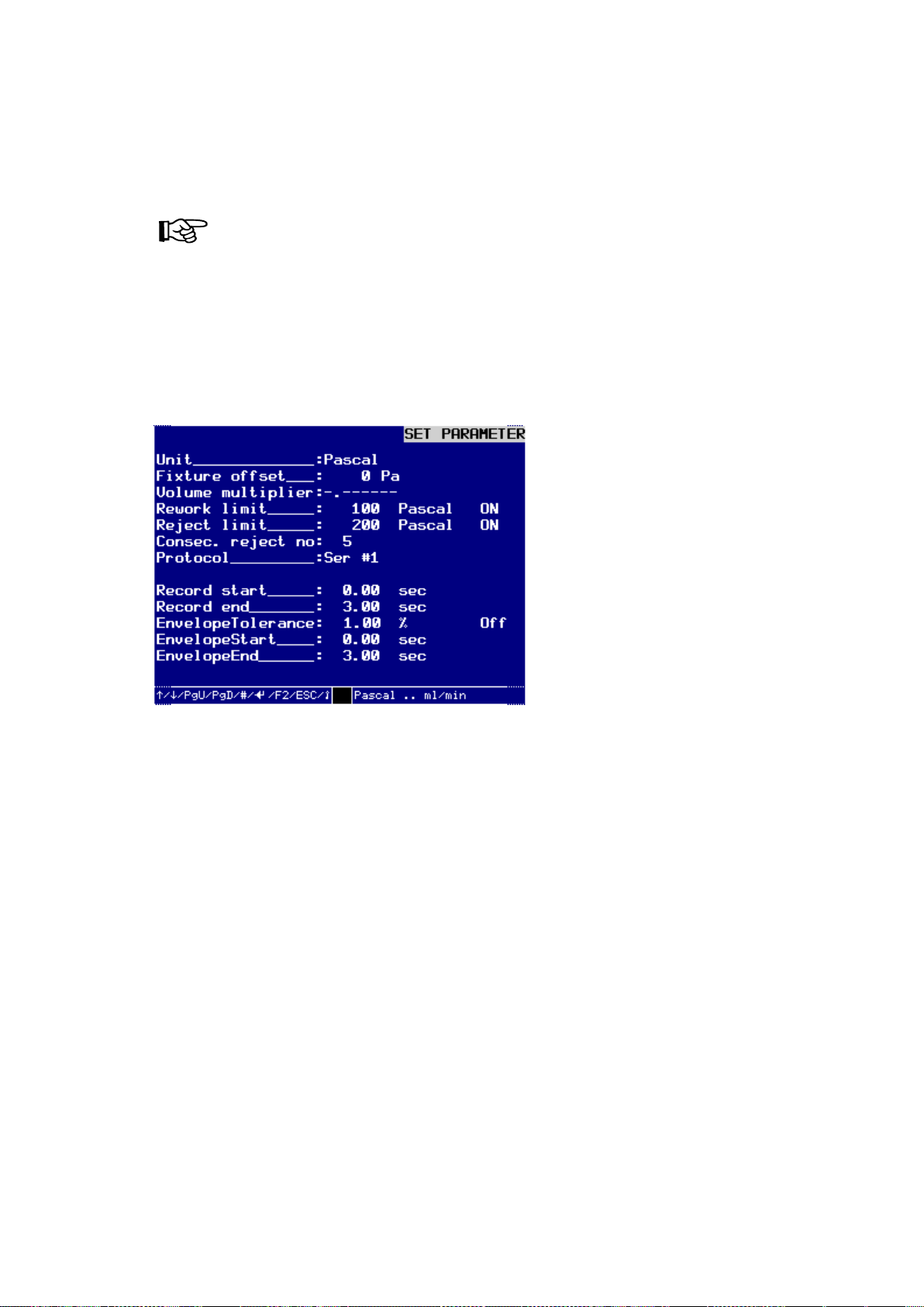
After these inputs and pressing the SHIFT + PgDn keys, or SHIFT + PgUp keys, the
second page of the dialog SET PARAMETER is displayed:
Continuation of dialog window SET PARAMETER
Unit:
The unit for the measuring value can be selected with the – and + keys: Pascal, mbar,
psi, mmWC, mmHg or ml/min.
Default setting is Pascal.
Fixture offset:
This value influences the zero point of the device. Depending on the direction of the
entered value, the zero point is reduced in case of negative values and increased in
case of positive values.
Enter the fixture offset from 0 … 999 Pa.
Default value is 0 Pa.
EN 3925-0060 V207-00 MANUAL R03.doc
HeMaTech
Prüftechnik
Page 48

Menu 3. SETUP Command reference
48
Volume multiplier =
known leak rate (ml/min)
measured value on measuring value display (Pa)
NOTE!
When parameters were changed, the conversion factor must be determined again.
NOTE!
Edit 0 disables this function.
Volume multiplier:
This value is for the calculation of the conversion of the measuring value to ml/min.
The factor must be 0.0001 … 9.9999. The default value is 1.0000.
To display the leak rate in ml/min the leak tester requires a volume multiplier.
This volume multiplier can be calculated with the following formula:
Rework Limit:
The intervention limit for rework must be 1 … 2000 mbar.
Default value is 100.
Rework ON/OFF
You can switch rework to ON or OFF with the – and + keys.
Default setting is ON.
Reject Limit:
The intervention limit for leaks must be 1 … 2000 mbar.
Default value is 200.
Consecutive reject number:
Here you can specify from which number of test results REJECT in direct consecutive
a fault is present. The limit for consecutive reject must be in the range from 0 … 999.
Default value is 5.
Protocol:
With the keys – and + you can choose the output channel for the test results: OFF, Ser
#1, Ser #2 (option), Ser #1 and Ser #2 (option):
Record start:
Enter the reference curve start point in seconds from 0.00 … 999.99.
Default value is 0.00 sec.
The start point of the reference curve is the point in time from which the reference
curve is recorded, after the leak test has been started.
Record end:
Enter the record end point in seconds from 0.10 … 999.99.
Default value is 3.00 sec.
EN 3925-0060 V207-00 MANUAL R03.doc
HeMaTech
Prüftechnik
Page 49

Command reference Menu 3. SETUP
49
NOTE!
If you turn the key switch to vertical position while entries are still
missing, an audible signal will sound and the display will show a
warning with the list of the still undefined parameters, into which the
device will automatically enter the standard values.
The end point of the record (reference curve) is the point in time at which recording of
the record is stopped, after the leak test has been started.
EnvelopTolerance:
The value should be 0.5 … 25.0 % and it is the tolerance of the permissible deviation
from the stored reference curve in % of the end value.
EnvelopTolerance ON/OFF:
You can switch enveloping curve tolerance to ON or OFF with the – and + keys.
Default setting is OFF.
EnvelopStart:
Enter the enveloping curve start point in seconds from 0.00 … 999.99.
Default value is 0.00 sec.
The start point of the enveloping curve is the point in time from which the deviation of the
enveloping curve from the reference curve is recorded, after the leak test has been started.
EnvelopEnd:
Enter the enveloping curve end point in seconds from 0.10 … 999.99.
Default value is 3.00 sec.
The end point of the enveloping curve is the point in time at which the evaluation of
the enveloping curve's deviation from the reference curve is stopped, after the leak test
has been started.
Saving the test program
By pressing the keys SHIFT + PgDn keys, or SHIFT + PgUp you can view both menu
pages again and make changes, which may be necessary. Once you have made all
desired changes in this dialog window, you can save these data.
To do so:
Turn the key switch anti-clockwise to vertical position.
An audible signal will sound and the changed data will be written to the RAM
memory.
Pull off the write protection switch in vertical ON-position, to avoid undesired
changes.
If you want to exit the menu without saving:
Press the ESC-key.
The first dialog window SET PARAMETER is displayed again.
Press the ESC-key again, to return to the dialog window SETUP.
EN 3925-0060 V207-00 MANUAL R03.doc
HeMaTech
Prüftechnik
Page 50

Menu 3. SETUP Command reference
50
Checking the plausibility of inputs
Before the test parameters are written into the RAM memory, all entered parameters
are subjected to a plausibility check:
Rework Limit < Reject Limit.
If the values do not meet the specifications, the program will adjust the corresponding
parameters accordingly and shows this by inverse representation in the display. You
may either correct the parameters, or accept them in the changed form.
EN 3925-0060 V207-00 MANUAL R03.doc
HeMaTech
Prüftechnik
Page 51
Command reference Menu 3. SETUP
51
1.1 Printout PARAMETER
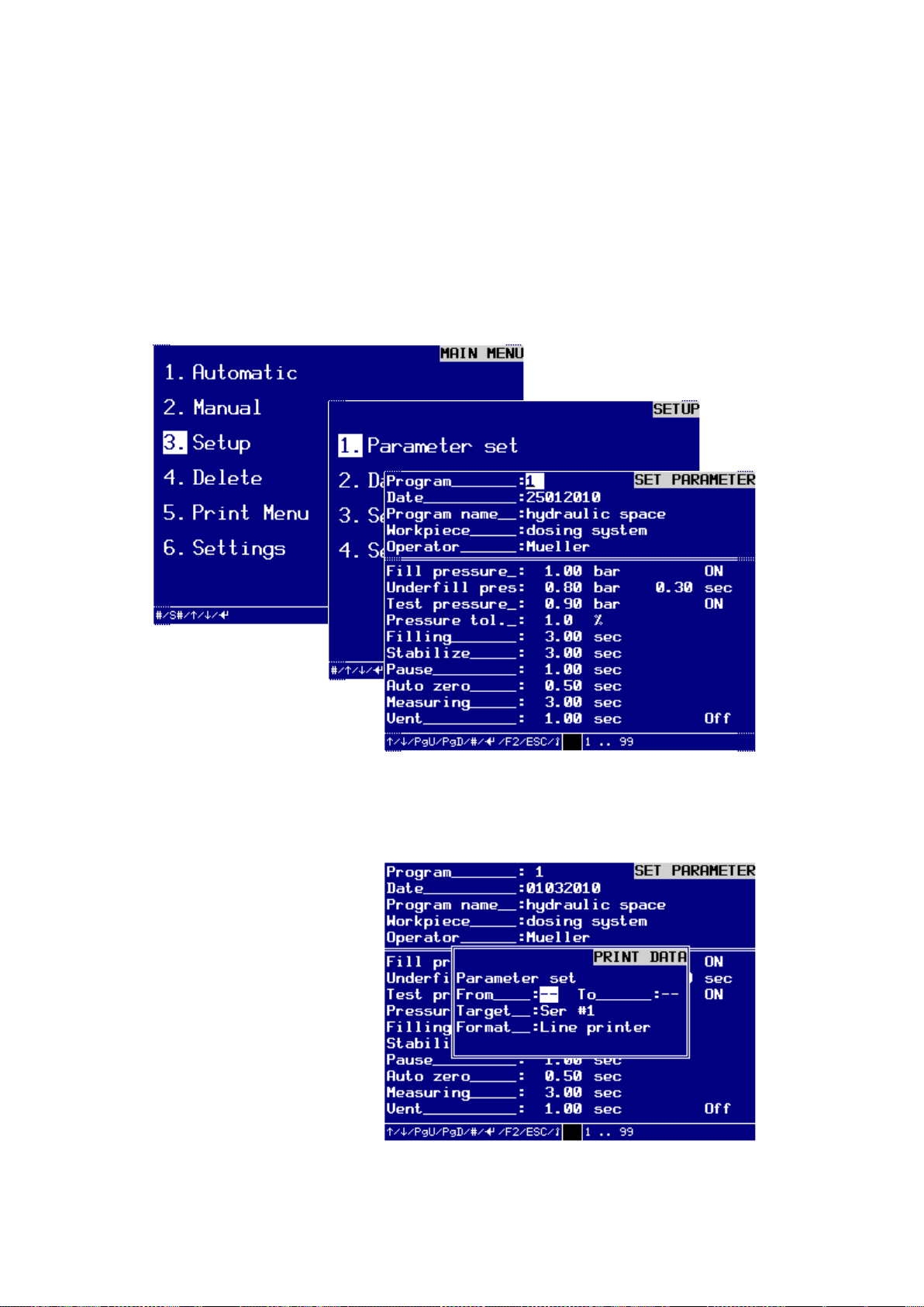
Here you can decide whether the program parameters should be shown on the display
or be printed out via an interface. Additional you can select which program parameters should be displayed or printed out.
In the MAIN MENU / 3. Setup you will find the dialog menu SETUP.
In the Menü SETUP / 1. Parameter set you can select the program number. The program parameters will be shown in the display.
Dialog window SET PARAMETER
Press key F2 to activate the dialog window PRINT DATA for data transfer via in-
terface.
On the display appears the window Print Data.
Set Parameter – Print Data
EN 3925-0060 V207-00 MANUAL R03.doc
HeMaTech
Prüftechnik
Page 52

Menu 3. SETUP Command reference
52
NOTE!
With a data output to a USB stick or external hard drive a file will be
automatically generated. The file name consists of the serial number
and the ending PAR.
e.g. 10100100.PAR.
If a file with same file name already exists, the file will be opened and
the data append to the file.
from: / to:
Enter the range of previous program parameter you want to output into the text
fields from: und to:, and confirm these individually with the ENTER-key.
Possible entries range from 1 … 99.
Target:
Press the keys – and + to determine the desired TARGET for the data output:
You can select between:
Ser #1,
Ser #2,
USB-Stick.
Confirm the selection by pressing the ENTER-key.
Format:
Press the keys – and + to determine the desired FROMAT for the data output:
You can select between:
LINE printer.
Confirm the selection by pressing the ENTER-key.
You can output the selected program parameter through the selected interface by
pressing the F2-key.
The message Print data is active! is display in the display.
Press the ESC-key to exit the menu.
EN 3925-0060 V207-00 MANUAL R03.doc
HeMaTech
Prüftechnik
Page 53
Command reference Menu 3. SETUP
53
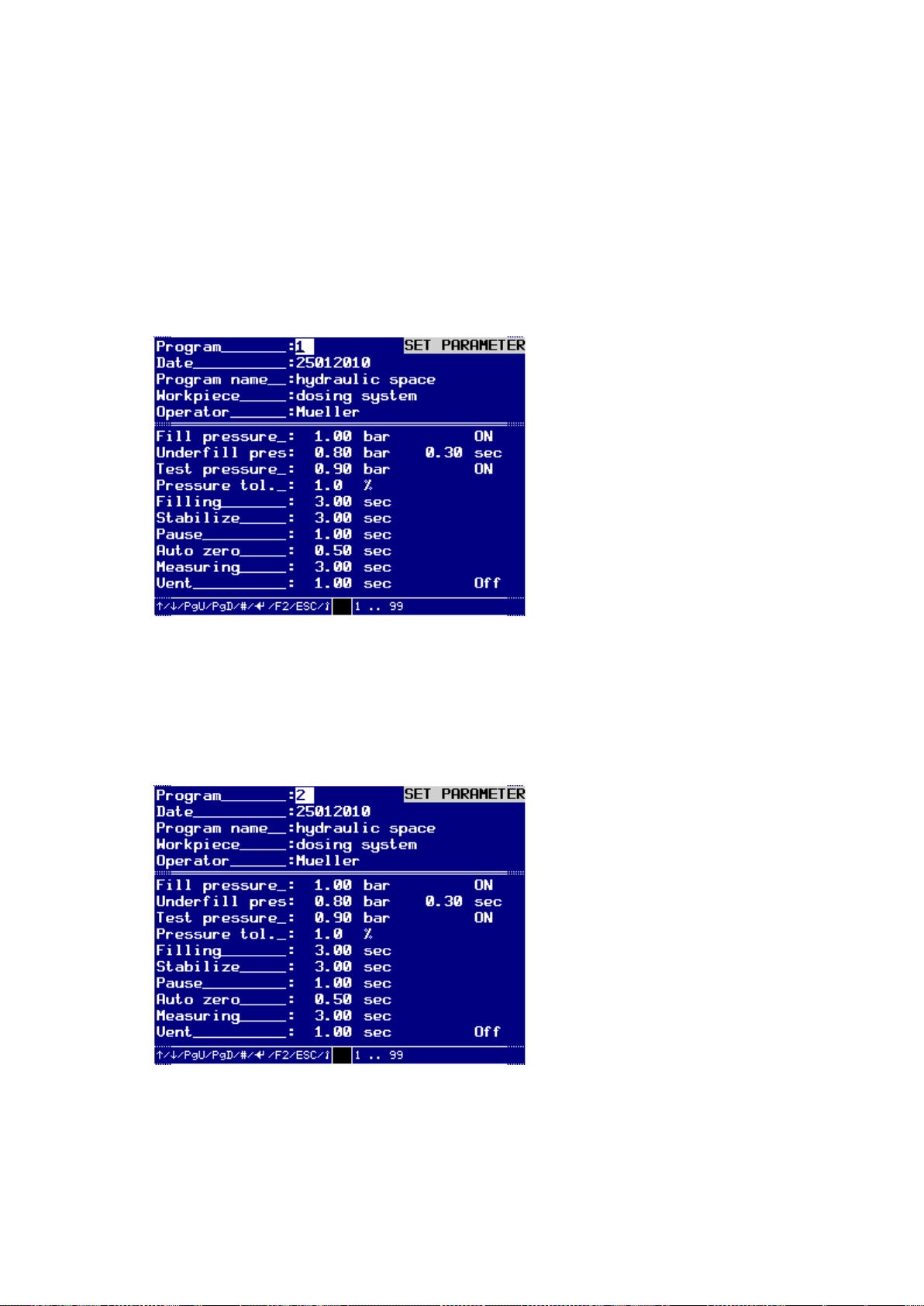
1.2 Copying an existing test program
If you would like to copy an existing test program, you must save it under a different
program number. To do so
Make sure that the key switch is in vertical write protection position.
Select the program to be copied from the dialog window TEST PROGRAMS by
Edit the number (1 … 99) into the field Program and confirm the selection by
pressing the ENTER-key.
The desired test program is displayed.
Test program to be copied
Turn the key switch clockwise to input mode.
Enter the new program number (1 …99) into the "Program" field.
Turn the key switch anti-clockwise to switch the write protection ON.
An audible signal will sound and the device saves the changed data to the RAM
memory.
Copied test program
Press the ESC-key to exit the menu.
EN 3925-0060 V207-00 MANUAL R03.doc
HeMaTech
Prüftechnik
Page 54
Menu 3. SETUP Command reference
54
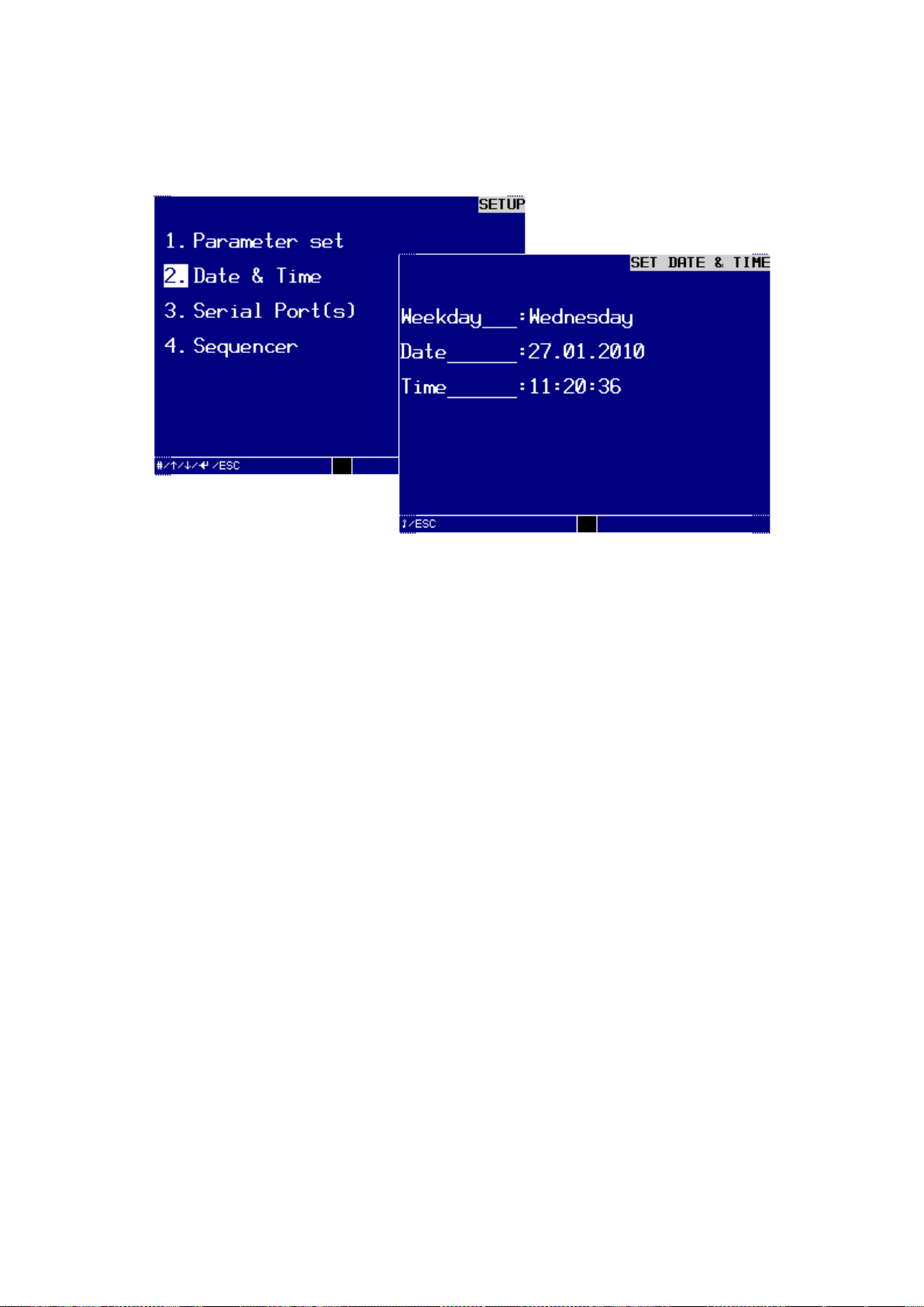
2. Date & Time.
In the dialog window SETUP DATE & TIME you can set or change data and time
Dialog window SETUP DATE & TIME
Turn the key switch clockwise to input mode, make the following entries and con-
firm each of them by pressing the ENTER-key:
Week day:
You can select the week day with the keys – or +.
Date:
Enter the day from 1 … 31 using the numerical keys.
Enter the month from 1 … 12 using the numerical keys.
Enter the year as a four-digit numerical value (e.g. 2010).
Time:
Enter the hour from 0 … 23 using the numerical keys.
Enter the minutes from 0 … 59 using the numerical keys.
Enter the seconds from 0 … 59 using the numerical keys.
Make sure that you have also confirmed the last entry for the seconds with the
ENTER-key.
Turn the key switch back to write protection ON.
An audible signal will sound and the device saves the changed data to the RAM
memory.
Press the ESC-key to exit the menu.
EN 3925-0060 V207-00 MANUAL R03.doc
HeMaTech
Prüftechnik
Page 55
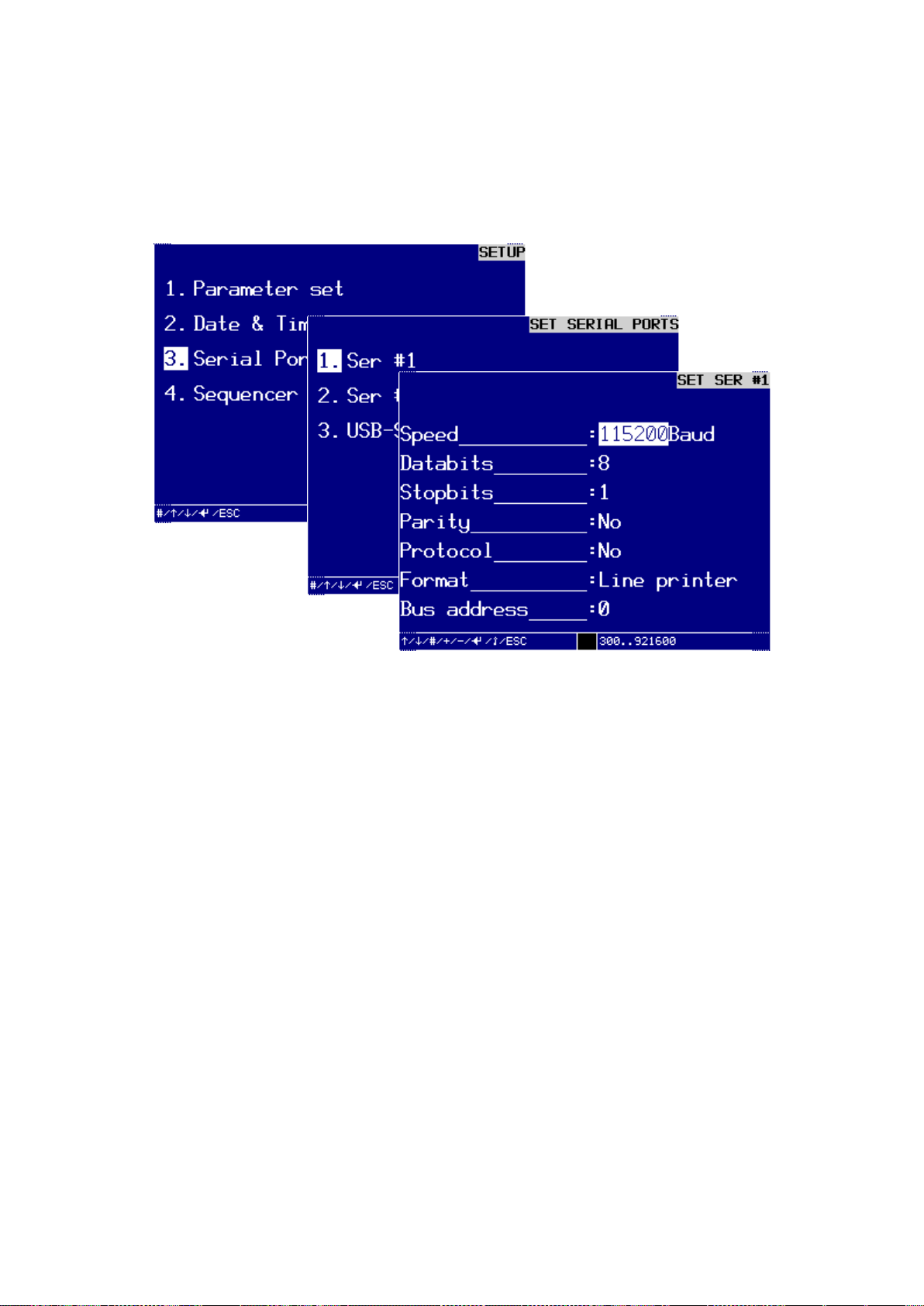
Command reference Menu 3. SETUP
55
3. Serial ports
In the dialog window SET SERIAL PORTS you can set up or change interface(s). The
interface Ser #1 is available as standard. The interfaces Ser # 2 … USB-Stick are op-
tional.
Dialog window SET SER #1
Output format line printer
Setting up an interface for a line printer
This section uses the interface SER #1 as an example for setting up the output format
for a line printer.
Turn key switch clockwise.
Write protection is disabled, entries can be made.
Make all following entries and confirm these individually by pressing the ENTER-
key. The cursor jumps to the next field.
Speed:
You can select the transfer speed with the keys – and +.
Data bits:
You can use the keys – and + to select the number (7 or 8) of data bits.
Stop bits:
You can use the keys – and + to select the number (1 or 2) of stop bits.
EN 3925-0060 V207-00 MANUAL R03.doc
HeMaTech
Prüftechnik
Page 56

Menu 3. SETUP Command reference
56
NOTE!
The output format File is a simple possibility for the processing of
measuring results on a PC. This will only output the measuring results
of the currently running test.
The following sections contain further information to the individual
interface formats.
NOTE!
The interface type is determined by the hardware and cannot be
changed through the program.
Parity:
You can use the keys – and + to establish the type of parity check. The following are
available to choose from: Without, Even, Uneven.
Protocol:
You can specify the transfer protocol with the keys – and +. The following are availa-
ble to choose from: Without, XonXoff, RtsCts.
Format:
You can specify the transfer format with the keys – and +. The following are available
to choose from: Line printer, File 01, File 02 , Record and optional special formats,
such as REGISTER, REGISTER+TO, REGISTER+TO+CS.
Once you have made and checked all entries, you can save these data.
Turn the key switch back to the vertical write protection position.
An audible signal will sound and the device saves the changed data to the RAM
memory.
The interface has been setup for the line printer output format.
Press the ESC-key to exit the menu.
EN 3925-0060 V207-00 MANUAL R03.doc
HeMaTech
Prüftechnik
Page 57
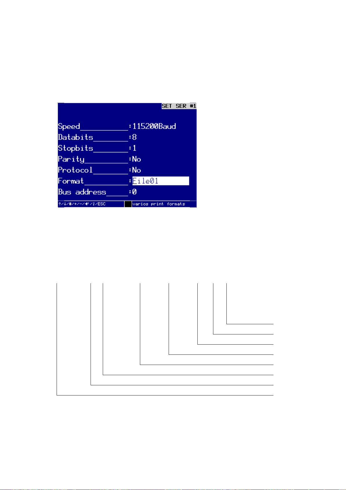
Command reference Menu 3. SETUP
57
00000001;
01;
01022004;
152621;
000000;
01;
01;
00
SerNo;
Pg;
DyMtYear;
HrMnSc;
Measva;
Unt;
Rs;
Er; …
Error number
with 2 digits
Result with 2 digits
Unit with 2 digits
Measuring value with 6 digits
Hour Minute Second with 6 digits
Day Month Year with 8 digits
Program number with 2 digits
Successive number with 8 digits
Output format File01
Set up / change the interface for format File 01 for data output to a PC.
Using the interface SER #1 as an example, this section explains how to set up the out-
put format for the output of File01 and File02 and which data will be output by the test
device.
Setting up an interface for the output of measuring data to a PC
In order to set up an interface for the output of measuring data to a PC, you should
select the Format: File01 or File02.
These two output files differ by the volume of measuring data.
The measuring data of File01
In output format File01 contains 8 measuring results in numerical format, each divided
by a semicolon. Example of a measuring result:
EN 3925-0060 V207-00 MANUAL R03.doc
HeMaTech
Prüftechnik
Page 58

Menu 3. SETUP Command reference
58
Serial number:
The serial number consists of 8 digits and starts with 00000001 when the device is
switched on. Once the counter has reached 99999999, it will automatically restart at
00000001.
Program number:
The number of the executed test program in the range from 01 … 99.
Day Month Year:
The date of testing consists of 8 digits: 2 digits for the day, 2 digits for the months, 4
digits for the year.
Hour Minute Second:
The time of testing consists of 6 digits. 2 digits each for hour, minute and second.
Measuring value:
The measured value with floating point representation matches the chosen unit. The
output width is always 6 digits. Error messages or the measuring result "Coarse Leak"
are represented by 6 minus dashes.
Unit:
The two-digit numerical value specifies the unit of the executed test program:
01 = Pa / ml/min
02 = mbar / ml/h
03 = PSI / l/min
04 = mmWC / l/h
05 = mmHg / m³/min
06 = ml/min / m³/h or %
Result:
The two-digit numerical value specifies the measuring result of the executed test program:
01 = I.O. / I.O.
02 = Rework 1 / LT
03 = Leak / UT
06 = Leak / Coarse Leak (Major leak)
-- = Error messages are identified by 2 minus dashes.
EN 3925-0060 V207-00 MANUAL R03.doc
HeMaTech
Prüftechnik
Page 59

Command reference Menu 3. SETUP
59
00
No Error
01
No operating pressure
02
Memory card missing
03
Program missing
04
Transmitter defective
05
Pressure switch S2 defective
06
Pressure switch S3 defective
07
Pressure not adjustable
08
No pressure in test system
09
No pressure in specimen
10
Coarse leak in reference volume
11
Pressure after filling valve
12
Shut-off valve open
13
Leak in reference volume
14
Series fault
15
Temperature value too low
16
not available
17
Overflow absolute pressure
transducer
18
Limit contact
"Leak" cannot be reached
19
Pressure increases after shutting
off
20
Apex not reached
21
Differential pressure switch not off
22
Differential pressure switch not on
23
Filling pressure too low
24
Filling pressure to high
25
Test pressure too low
26
Test pressure to high
27
Pressure system not adjustable
28
Rated pressure out of range
29
Incorrect pre-selection
30
Hook 1 missing (optional)
31
Hook 2 missing (optional)
32
Hooks 1 +2 missing (optional)
33
Pressure switch S4 defective
34
Pressure correction value too high
35
Pressure in reference volume to
low or flow-in time too short
36
Pressure in reference volume too
high
37
Test pressure in sequence too low
38
Test pressure in sequence too
high
Error number:
The two-digit numerical value specifies the type of the error of the executed test pro-
gram that has occurred:
The output of some of the error numbers depends on device type or options. If the
number of the error is <> 0, minus symbols will be displayed for measuring value and
measuring result.
If a numerical value cannot be displayed in the defined output format, the field will be
output with "" (Code 18H) when exceeded, or with "" (Code 19H)
when fallen short of. The individual positions are separated by semicolon. The data set
is closed with a carriage return and a line feed (CR+LF).
Examples:
No Leak 00000001;01;01022000;152621;000000;01;01;00
Gross leak 00000002;01;01022000;152637;------;01;04;00
Fault 00000003;01;01022000;152718;------;01; --;25
EN 3925-0060 V207-00 MANUAL R03.doc
HeMaTech
Prüftechnik
Page 60
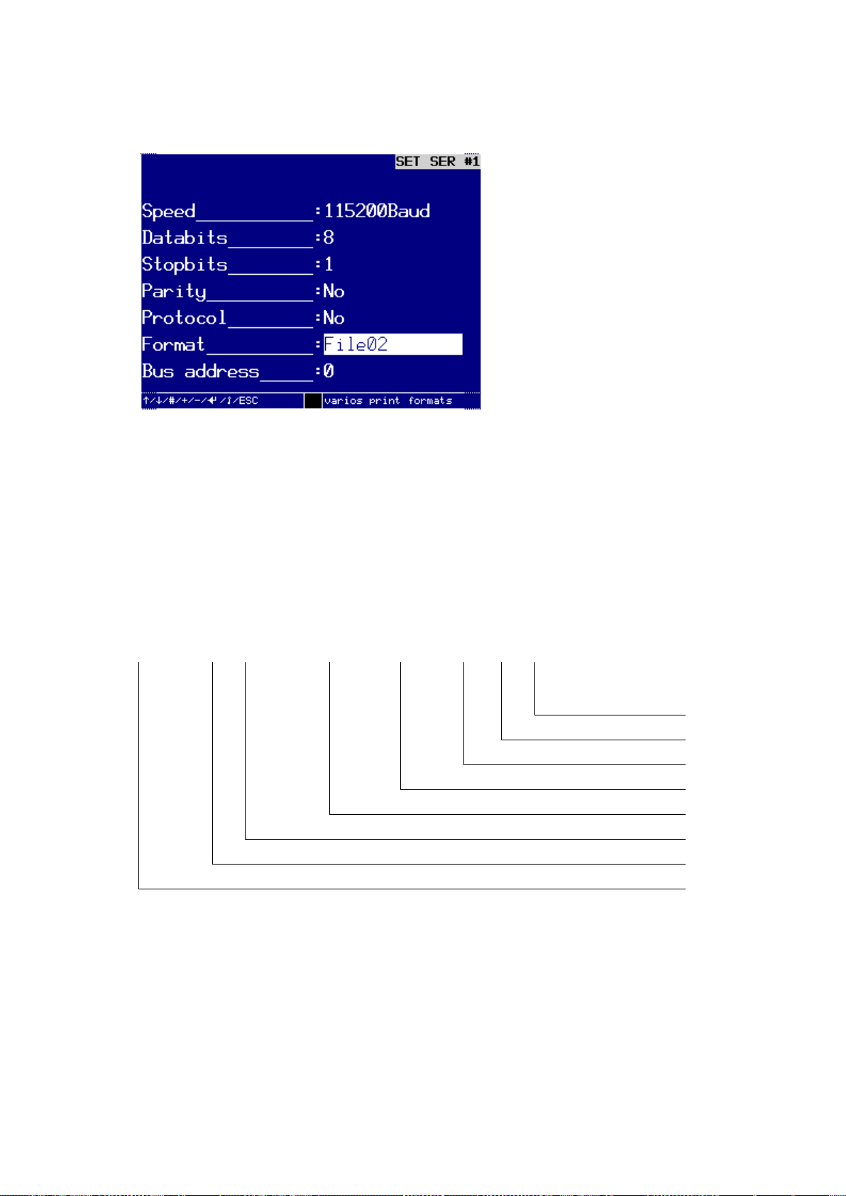
Menu 3. SETUP Command reference
60
SerNo;
Pg;
DyMtYear;
HrMnSc;
Measva;
Unt;
Rs;
Er; …
Error-No. with 2 digits
Result with 2 digits
Unit with 2 digits
Measuring value with 6 digits
Hour Minute Second with 6 digits
Day Month Year with 8 digits
Program number with 2 digits
Successive number with 8 digits
Output format File02
Setting the output format File02
The measuring data of File02
If you choose the format File02 for the data output, five more measuring data will be
output in addition to the measuring data of format File01, i.e. a total of 13, which are
each separated by semicolon.
Example of a measuring result:
00000001;01;24022002;152621;000000;01;01;00;1,00:3,00;1,0000000;50;10
0
(here NO LEAK)
EN 3925-0060 V207-00 MANUAL R03.doc
HeMaTech
Prüftechnik
Page 61

Command reference Menu 3. SETUP
61
… Test
pressure;
Measuring
time;
Volume factor;
Rework;
Leak
Leak with 6 digits
Rework with 6 digits
Volume factor with 9 or 6 digits
Measuring time with 6 digits
Test pressure with 6 digits
Continued
In addition to the measuring data in format Datei01 format Datei02 will also provide
the following data:
Test pressure:
Specifies the test pressure for the test with 6 digit. The output width is always 6 digits.
The unit for the test pressure is bar/ü.
Measuring time:
Shows the entered measuring time in a structured representation. The unit for the
measuring time is seconds.
Volume multiplier:
Shows the volume multiplier, used to calculate the measuring values, in a structured
representation. The output width is always 9 or 6 digits.
Rework:
Specifies the limit contact for rework in the adapted structured representation. The
output width is always 6 digits.
Reject:
Specifies the limit contact for leak in the adapted structured representation. The output
width is always 6 digits.
Examples for the output of measuring data in the format File02.
Accept
00000001;01;24022002;152621;000000;01;01;00;1,00:3,00;1,0000000;50;100
Gross leak (major leak)
00000002;01;24022002;152637;------;01;04;00;1,00:3,00;1,0000000;50;100
Error
00000003;01;24022002;152718;------;01; --;25;1,00:3,00;1,0000000;50;100
EN 3925-0060 V207-00 MANUAL R03.doc
HeMaTech
Prüftechnik
Page 62
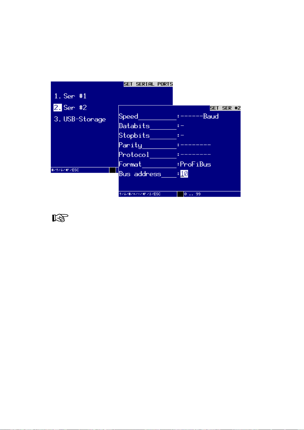
Menu 3. SETUP Command reference
62
NOTE!
Make sure that the hardware for Profibus is installed
View:
6. SETTINGS\2.SYSTEM PARAMETER\SET SER #2:
RS232 57600 8 1 None XON/XOFF Profbus 10
Speed:
9600 … 115200 Baud
Data bits:
8
Stop bits:
1
Parity:
None
Protocol:
None
Format:
Profibus
Bus address:
0 … 99
3.1 Output format Profibus
Setting up the serial interface SER#2 for Profibus (optional)
If you would like to set up the serial interface SER #2 for Profibus, you must call up the
dialog window SET SER #2:
Dialog window SET SER #2 to set up for Profibus
In the dialog window SETUP SER #2:
Format:
You can specify the transfer format with the keys – and +. The following are available
to choose from: Line printer, File 01, File 02, Profibus, Record and optional special
formats, such as REGISTER, REGISTER+TO, REGISTER+TO+CS.
EN 3925-0060 V207-00 MANUAL R03.doc
HeMaTech
Prüftechnik
Page 63

Command reference Menu 3. SETUP
63
Description
Type
Byte/Bit
3925-0050 LEAK
3925-0150
FLOW
3925-0350
VOLUME
Input
1.0
Internal reserved
Input
1.1
Internal reserved
Input
1.2
Internal reserved
Input
1.3
Internal reserved
Input
1.4
Internal reserved
Input
1.5
Internal reserved
Input
1.6
Internal reserved
Input
1.7
Internal reserved
Input
2 . 0
Machine ready
Input
2 . 1
Start
Input
2 . 2
Leak simulation
Reserve
Reserve
Input
2 . 3
Static test (Flooding)
Reserve
Input
2 . 4
Abort
Input
2 . 5
Automatic
Input
2 . 6
Reserve
Input
2 . 7
Reserve
Input
3 .0
BCD 01 (Program selection)
Input
3 . 1
BCD 02 (Program selection)
Input
3 . 2
BCD 04 (Program selection)
Input
3 . 3
BCD 08 (Program selection)
Input
3 . 4
BCD 10 (Program selection)
Input
3 . 5
BCD 20 (Program selection)
Input
3 . 6
BCD 40 (Program selection)
Input
3 . 7
BCD 80 (Program selection)
Input
4.0
External reserve
Input
4.1
External reserve
Input
4.2
External reserve
Input
4.3
External reserve
Input
4.4
External reserve
Input
4.5
External reserve
Input
4.6
External reserve
Input
4.7
External reserve
The Profibus inputs and outputs
If the Profibus is activated, it will take over the following inputs/outputs:
EN 3925-0060 V207-00 MANUAL R03.doc
HeMaTech
Prüftechnik
Page 64

Menu 3. SETUP Command reference
64
Description
Type
Byte/Bit
3925-0050 LEAK
3925-0150
FLOW
3925-0350
VOLUME
5.0
Not used
5.1
Not used
5.2
Not used
5.3
Not used
5.4
Not used
5.5
Not used
5.6
Not used
5.7
Not used
6.0
Not used
6.1
Not used
6.2
Not used
6.3
Not used
6.4
Not used
6.5
Not used
6.6
Not used
6.7
Not used
Output
1.0
Internal reserved
Output
1.1
Internal reserved
Output
1.2
Internal reserved
Output
1.3
Internal reserved
Output
1.4
Internal reserved
Output
1.5
Internal reserved
Output
1.6
Internal reserved
Output
1.7
Internal reserved
2.0
Not used
2.1
Not used
2.2
Not used
2.3
Not used
2.4
Not used
2.5
Not used
2.6
Not used
2.7
Not used
EN 3925-0060 V207-00 MANUAL R03.doc
HeMaTech
Prüftechnik
Page 65

Command reference Menu 3. SETUP
65
Description
Type
Byte/Bit
3925-0050 LEAK
3925-0150
FLOW
3925-0350
VOLUME
Output
3.0
External reserved
Output
3.1
External reserved
Output
3.2
External reserved
Output
3.3
External reserved
Output
3.4
External reserved
Output
3.5
External reserved
Output
3.6
External reserved
Output
3.7
External reserved
4.0
External reserve
4.1
External reserve
4.2
External reserve
4.3
External reserve
4.4
External reserve
4.5
External reserve
4.6
External reserve
4.7
External reserve
5.0
Not used
5.1
Not used
5.2
Not used
5.3
Not used
5.4
Not used
5.5
Not used
5.6
Not used
5.7
Not used
Output
6 . 0
Ready for operation
Output
6 . 1
Fault
Output
6 . 2
Ready for test
O.K.
Output
6 . 3
Rework / LT
Ready for test
Output
6 . 4
Reject / UT
LT (Min)
Output
6 . 5
No leak / O.K.
Reserve
Output
6 . 6
Enveloping curve
Filling n.o.k. (optional)
Measuring active
Output
6 . 7
Measuring active
UT (Max)
EN 3925-0060 V207-00 MANUAL R03.doc
HeMaTech
Prüftechnik
Page 66

Menu 3. SETUP Command reference
66
Description
Type
Byte/Bit
3925-0050 LEAK
3925-0150
FLOW
3925-0350
VOLUME
Output
7 . 0 ... 7
Measuring value identifier
Output
8 . 0 ... 7
1. Digit measuring value
Output
9 . 0 ... 7
2. Digit measuring value
Output
10 . 0 ... 7
3. Digit measuring value
Output
11 . 0 ... 7
4. Digit measuring value
Output
12 . 0 ... 7
5. Digit measuring value
Output
13 . 0 ... 7
6. Digit measuring value
Output
14 . 0 ... 7
7. Digit measuring value
Output
15 – 0 ... 7
7. Digit measuring value
Output
16 . 0 ... 7
9. Digit measuring value
Output
17 . 0 ... 7
10. Digit measuring value
Output
18 . 0 ... 7
11. Digit measuring value
Output
19 .0 ... 7
12. Digit measuring value
Output
20 . 0 ... 7
13. Digit measuring value
Output
21 . 0 ... 7
14. Digit measuring value
Output
22 . 0 ... 7
15. Digit measuring value
Output
23 . 0 ... 7
16. Digit measuring value
The following identifier are possible:
ASCII „0“ = Measuring value invalid
ASCII „1“ = Measuring value in measuring range 1
ASCII „2“ = Measuring value in Measuring range 2
ASCII „3“ = Measuring value in Measuring range 3
ASCII „4“ = Measuring value in Measuring range 4
ASCII „5“ = Measuring value in Measuring range 5
ASCII „6“ = Measuring value in Measuring range 6
ASCII „G“ = Gross leak
ASCII „H“ = Envelop curve leaving
ASCII „F“ = Error
The measuring value occupies 17 output bytes on the Profibus starting from the 7th
output byte. All data outputs take place in the ASCII format.
For devices with Profibus you require the file PLC07v100.GSD for configuring the Profibus Master, this file is delivered on a separate CD.
EN 3925-0060 V207-00 MANUAL R03.doc
HeMaTech
Prüftechnik
Page 67
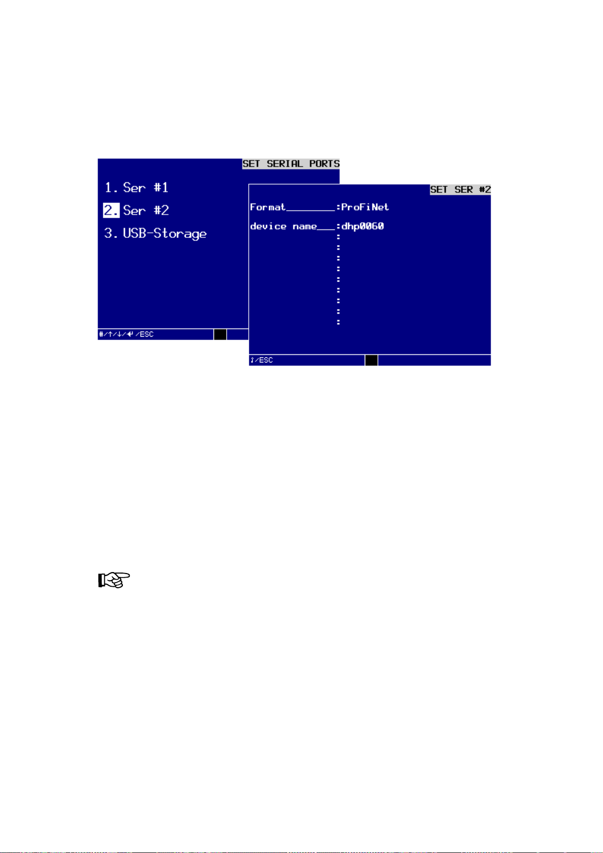
Command reference Menu 3. SETUP
67
Format:
Profinet (not editable)
Device name:
dhp0060
NOTE!
The interface format is defined by the hardware and can not be
changed via the program.
3.2 Output format Profinet
Setting up the serial interface SER#2 for Profinet (optional)
If you would like to set up the serial interface SER #2 for Profinet, you must call up the
dialog window SET SER #2:
Dialog window SET SER #2 to set up for Profinet
Profinet-Functions
The Profinet module supports a maximum data rate of 128 byte input and 128 byte
output data as well as all baud rates from 9.6 kbit / s to 12 Mbps. Baud rate detection
is performed automatically.
The Profinet station address can be accessed via the menu
3. SETUP \ 3. SET SERIAL PORTS \ 2. SER #2
Make the following settings in the dialog window SETUP SER #2:
The test device with Profinet interface has 6 input bytes and 17 output bytes.
The breakdown is as follows.
The naming conventions of Profinet must be observed.
EN 3925-0060 V207-00 MANUAL R03.doc
HeMaTech
Prüftechnik
Page 68

Menu 3. SETUP Command reference
68
Description
Type
Byte/Bit
3925-0060 LEAK
3925-0160
FLOW
3925-0360
VOLUME
Input
1.0
Internal reserved
Input
1.1
Internal reserved
Input
1.2
Internal reserved
Input
1.3
Internal reserved
Input
1.4
Internal reserved
Input
1.5
Internal reserved
Input
1.6
Internal reserved
Input
1.7
Internal reserved
Input
2 . 0
Machine ready
Input
2 . 1
Start
Input
2 . 2
Leak simulation
Reserve
Reserve
Input
2 . 3
Static test (Flooding)
Reserve
Input
2 . 4
Abort
Input
2 . 5
Automatic
Input
2 . 6
Reserve
Input
2 . 7
Reserve
Input
3 .0
BCD 01 (Program selection)
Input
3 . 1
BCD 02 (Program selection)
Input
3 . 2
BCD 04 (Program selection)
Input
3 . 3
BCD 08 (Program selection)
Input
3 . 4
BCD 10 (Program selection)
Input
3 . 5
BCD 20 (Program selection)
Input
3 . 6
BCD 40 (Program selection)
Input
3 . 7
BCD 80 (Program selection)
Input
4.0
External reserve
Input
4.1
External reserve
Input
4.2
External reserve
Input
4.3
External reserve
Input
4.4
External reserve
Input
4.5
External reserve
Input
4.6
External reserve
Input
4.7
External reserve
The Profinet inputs and outputs
If the Profinet is activated, it will take over the following inputs/outputs:
EN 3925-0060 V207-00 MANUAL R03.doc
HeMaTech
Prüftechnik
Page 69

Command reference Menu 3. SETUP
69
Description
Type
Byte/Bit
3925-0060 LEAK
3925-0160
FLOW
3925-0360
VOLUME
5.0
Not used
5.1
Not used
5.2
Not used
5.3
Not used
5.4
Not used
5.5
Not used
5.6
Not used
5.7
Not used
6.0
Not used
6.1
Not used
6.2
Not used
6.3
Not used
6.4
Not used
6.5
Not used
6.6
Not used
6.7
Not used
Output
1.0
Internal reserved
Output
1.1
Internal reserved
Output
1.2
Internal reserved
Output
1.3
Internal reserved
Output
1.4
Internal reserved
Output
1.5
Internal reserved
Output
1.6
Internal reserved
Output
1.7
Internal reserved
2.0
Not used
2.1
Not used
2.2
Not used
2.3
Not used
2.4
Not used
2.5
Not used
2.6
Not used
2.7
Not used
EN 3925-0060 V207-00 MANUAL R03.doc
HeMaTech
Prüftechnik
Page 70

Menu 3. SETUP Command reference
70
Description
Type
Byte/Bit
3925-0060 LEAK
3925-0160
FLOW
3925-0360
VOLUME
Output
3.0
External reserved
Output
3.1
External reserved
Output
3.2
External reserved
Output
3.3
External reserved
Output
3.4
External reserved
Output
3.5
External reserved
Output
3.6
External reserved
Output
3.7
External reserved
4.0
External reserve
4.1
External reserve
4.2
External reserve
4.3
External reserve
4.4
External reserve
4.5
External reserve
4.6
External reserve
4.7
External reserve
5.0
Not used
5.1
Not used
5.2
Not used
5.3
Not used
5.4
Not used
5.5
Not used
5.6
Not used
5.7
Not used
Output
6 . 0
Ready for operation
Output
6 . 1
Fault
Output
6 . 2
Ready for test
O.K.
Output
6 . 3
Rework / LT
Ready for test
Output
6 . 4
Reject / UT
LT (Min)
Output
6 . 5
No leak / O.K.
Reserve
Output
6 . 6
Enveloping curve
Filling n.o.k. (optional)
Measuring active
Output
6 . 7
Measuring active
UT (Max)
EN 3925-0060 V207-00 MANUAL R03.doc
HeMaTech
Prüftechnik
Page 71

Command reference Menu 3. SETUP
71
Description
Type
Byte/Bit
3925-0060 LEAK
3925-0160
FLOW
3925-0360
VOLUME
Output
7 . 0 ... 7
Measuring value identifier
Output
8 . 0 ... 7
1. Digit measuring value
Output
9 . 0 ... 7
2. Digit measuring value
Output
10 . 0 ... 7
3. Digit measuring value
Output
11 . 0 ... 7
4. Digit measuring value
Output
12 . 0 ... 7
5. Digit measuring value
Output
13 . 0 ... 7
6. Digit measuring value
Output
14 . 0 ... 7
7. Digit measuring value
Output
15 – 0 ... 7
7. Digit measuring value
Output
16 . 0 ... 7
9. Digit measuring value
Output
17 . 0 ... 7
10. Digit measuring value
Output
18 . 0 ... 7
11. Digit measuring value
Output
19 .0 ... 7
12. Digit measuring value
Output
20 . 0 ... 7
13. Digit measuring value
Output
21 . 0 ... 7
14. Digit measuring value
Output
22 . 0 ... 7
15. Digit measuring value
Output
23 . 0 ... 7
16. Digit measuring value
The following identifier are possible:
ASCII „0“ = Measuring value invalid
ASCII „1“ = Measuring value in measuring range 1
ASCII „2“ = Measuring value in Measuring range 2
ASCII „3“ = Measuring value in Measuring range 3
ASCII „4“ = Measuring value in Measuring range 4
ASCII „5“ = Measuring value in Measuring range 5
ASCII „6“ = Measuring value in Measuring range 6
ASCII „G“ = Gross leak
ASCII „H“ = Envelop curve leaving
ASCII „F“ = Error
The measuring value occupies 17 output bytes on the Profinet starting from the 7th
output byte. All data outputs take place in the ASCII format.
For devices with Profinet you require the GSDML-file for configuring the Profinet Master, this file is delivered on a separate USB-Stick.
EN 3925-0060 V207-00 MANUAL R03.doc
HeMaTech
Prüftechnik
Page 72
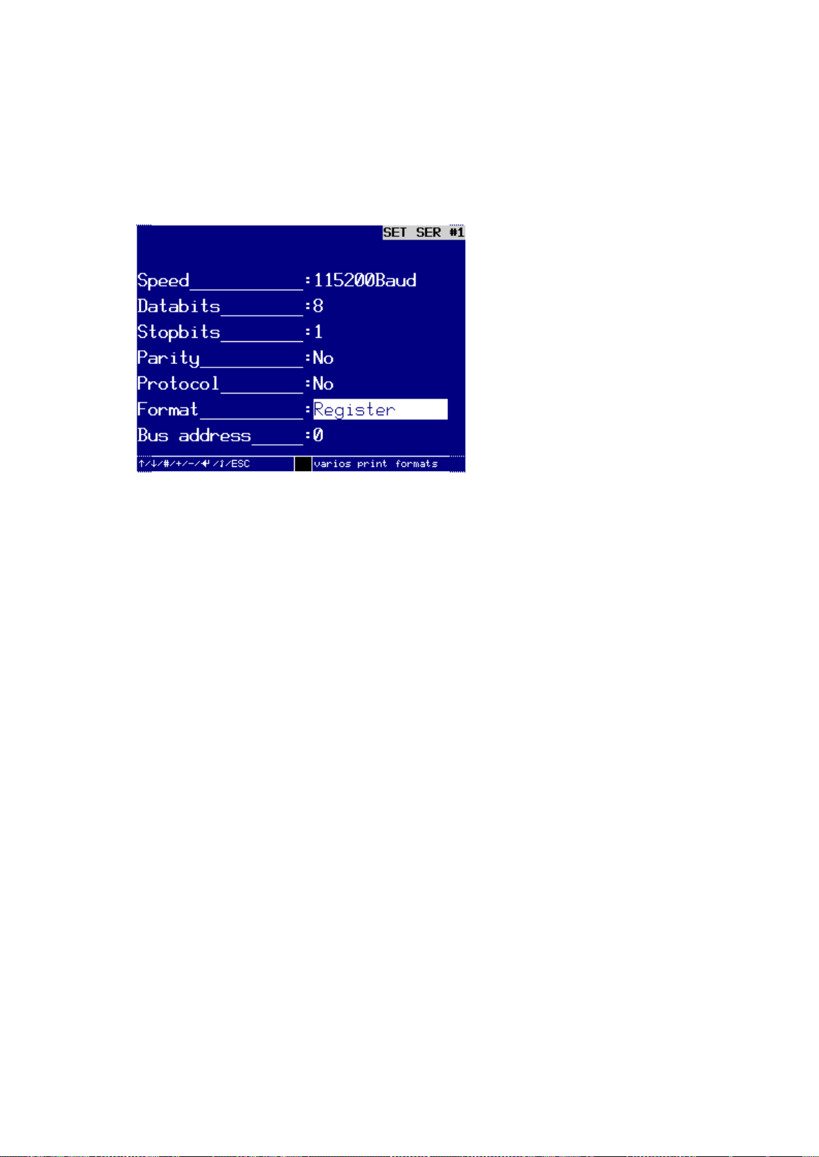
Menu 3. SETUP Command reference
72
Remote control via serial interface
Setting up or changing the interface for remote controlling of the device
This section uses the interface SER #1 as an example for setting up the output format
REGISTER or REGISTER+TO or REGISTER+TO+CS.
Dialog windows for setting up an interface for a special format
In order to set up an interface for the output of data to a PC in a special format, you
should select the Format: REGISTER or REGISTER+TO or REGISTER+TO+CS.
These three output formats are special formats and serve the remote controlling of the
tester via the serial interface. For remote controlling purposes the user is provided with
a powerful set of commands.
Protocol for the complete control for all functions and parameters for the
test device. The following information describes the functions in detail:
EN 3925-0060 V207-00 MANUAL R03.doc
HeMaTech
Prüftechnik
Page 73

Command reference Menu 3. SETUP
73
Command
Function
Access
AINnnn
Analog input (Analog INput)
Read
AOUnnn
Analog output (Analog OUtput)
Read
DINnnn
Digital input (Digital INput)
Read/partially write
DOUnnn
Digital output (Digital OUtput)
Read
FILnnn
Filling curve (FILling curve)
Read
HSPnnn
Hardware system parameter
(Hardware SystemParameter)
Read
PVRnnn,nnn
Test program variable (Program VaRiables)
Read/write
REFnnn
Reference curve (REFerence curve)
Read/write
RSVnnn
Result storing variable (ResultStore Variables)
Read
RVRnnn
Result variable (Result VaRiables)
Read
SPVnnn,nnn
Sequencer parameter variables
(Sequencer Parameter Variables)
Read/write
SSPnnn
Program specific parameter
(Software SystemParameter)
Read
STAnnn
Status variable (STAtus variables)
Read
List of commands in alphabetical order
EN 3925-0060 V207-00 MANUAL R03.doc
HeMaTech
Prüftechnik
Page 74

Menu 3. SETUP Command reference
74
Structure of commands
Syntax:
For the query of values:
RegisterName<(Start)Indize>|[-<EndIndize>]|[;<Indize>;<Indize>;…][;CS]<CR>
For the setting of values:
RegisterName<Indize>=<Wert>[;CS]<CR>
or
RegisterName<StartIndize>-<EndIndize>=<Wert>;<Wert>;<Wert>;….[;CS]<CR>
or
RegisterName<Indize>;<Indize>;…=<Wert>;<Wert>;….[;CS]<CR>
Register names generally consist of 3 non-numerical characters.
Register names are accepted in upper and lower case letters.
A register name is always followed by an index, which can also be two-
dimensional. The dimensions are separated by a colon.
If a range is specified for two-dimensional indexes, both the start and the end in-
dex must be specified in two dimensions.
A register sequence must be terminated with <CR> at the latest after 127 characters.
Characters with an ASCII-value of less than 32 will be ignored or, in case of con-
trol characters, interpreted accordingly.
If a format is activated with time monitoring function and a started command se-
quence is not followed by the terminating <CR> at the latest after 100 msec, the
complete sequence will be ignored.
If the format is activated with checksum, only sequences with correct checksum will
be evaluated. The checksum is generated by non-transfer addition of all utilization
data via 8 bit and final formation of the one's complement. For output purposes
the checksum is appended to the utilization data as a two-digit hexadecimal number in form of ASCII-characters, separated by semicolon. For inputs the same format is expected.
Non-existing register sequences are ignored without any feedback (the correct execu-
tion of setting commands can be monitored by querying the corresponding register).
If the <Value> is a string, it will be transmitted in “ “ and, in case of a transfer,
this format is also expected.
There is no monitoring of whether values are inside the permissible range.
The transfer of impermissible values can lead to unexpected reactions of the device!
Parameters with "Read" access can be released for writing, if desired.
EN 3925-0060 V207-00 MANUAL R03.doc
HeMaTech
Prüftechnik
Page 75

Command reference Menu 3. SETUP
75
Command
Feedback
DOU1<CR>
0<CR>
Or
1<CR>
Command
Feedback
DOU1-2<CR>
0,0<CR>
Or
Or
DOU1;2<CR>
0,1<CR>
Or 1,0<CR>
Or
1,1<CR>
Command
DOU1=1<CR>
Command
DOU1-2=1;1<CR>
Or
DOU1;2=1;!<CR>
Examples:
Single enquiry of the status of test pressure valve "Y2" on
leak tester 3925-0050:
Multiple enquiry of the status of test pressure valve "Y2" and shut-off valve "Y3" on
leak tester 3925-0050:
Single setting of the status of test pressure valve "Y2" on
leak tester 3925-0050:
Multiple setting of the status of test pressure valve "Y2" and shut-off valve "Y3" on
leak tester 3925-0050:
Further information concerning the command reference can be found in the command
reference manual for the leak tester (PLC95).
EN 3925-0060 V207-00 MANUAL R03.doc
HeMaTech
Prüftechnik
Page 76
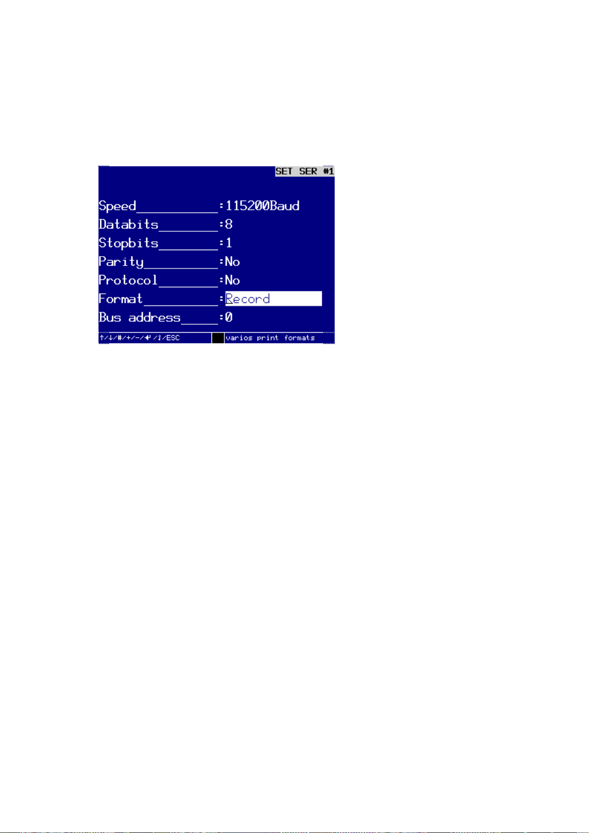
Menu 3. SETUP Command reference
76
Output format Record (Filling curve)
Setting up or changing the interface for record (filling curve) output
This section uses the interface SER #1 as an example for setting up the output format
for the record output.
Dialog window to set up the interface for Record data output
In order to set up an interface for the output of record data to a PC, you should select
the Format: Record.
EN 3925-0060 V207-00 MANUAL R03.doc
HeMaTech
Prüftechnik
Page 77
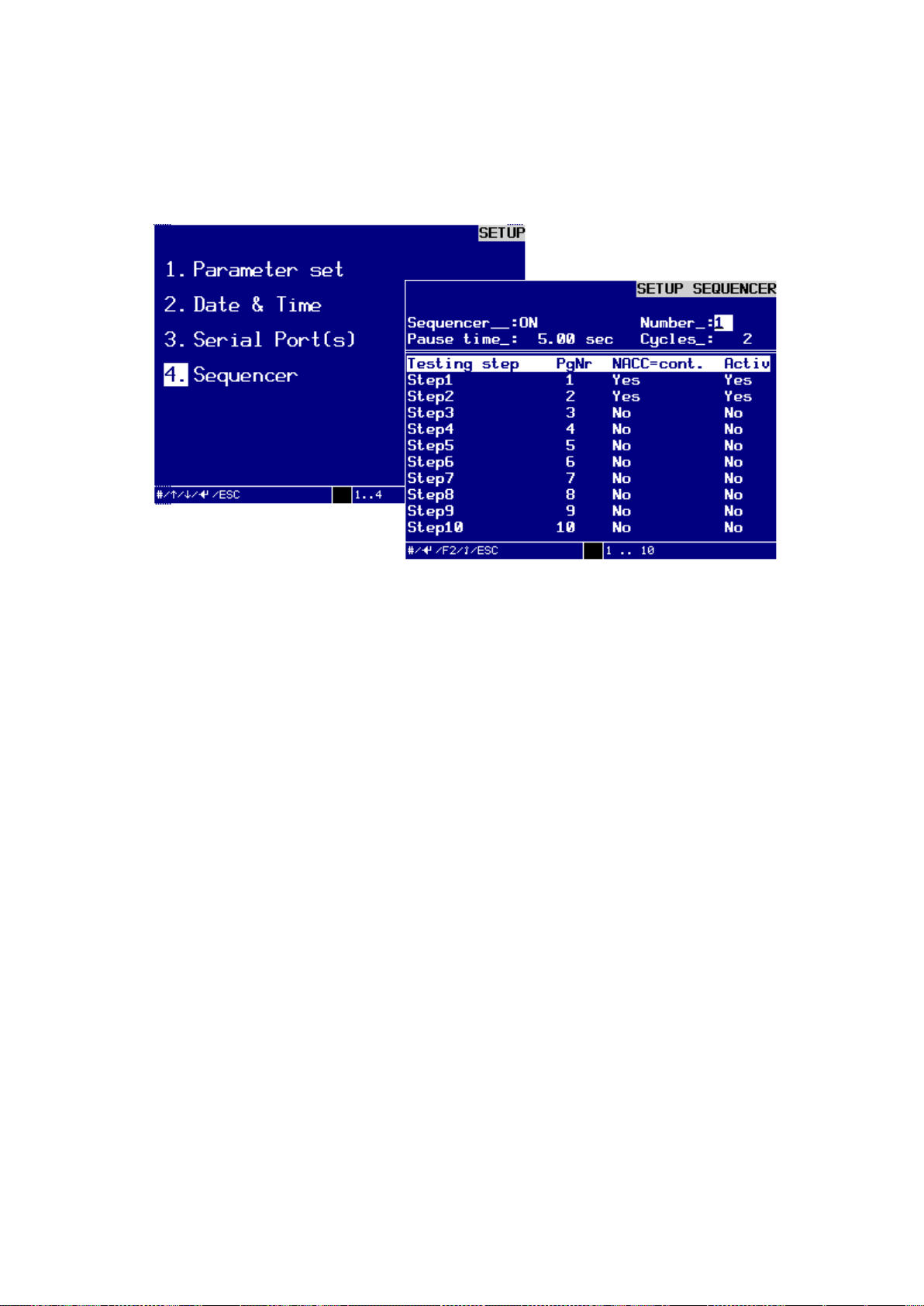
Command reference Menu 3. SETUP
77
4. Sequencer
In the dialog window SETUP SEQUENCER you can set up or change a testing se-
quence with max. 10 test steps.
Dialog window SETUP SEQUENCER
Turn the key switch clockwise to input mode, make the following entries and con-
firm each of them by pressing the ENTER-key:
Sequencer:
You can switch the sequencer to ON or OFF with the – and + keys.
The default setting is OFF.
Number:
Enter the sequence number using the numbers 1 … 10.
Pause time:
Enter the pause time in seconds from 0.10 … 999.99.
The default value is 0.00 sec.
The pause time is the time period to the start of the next sequencer cycle
Cycles:
Enter the cycles from 1 … 9999.
The default value is 1.
With the sequencer activated the sequences are repeated as often as specified under the
item "Cycles" when setting up the sequencer for the corresponding sequencer program.
Step 1 … 10:
For the steps of the test sequence enter a test program number using the numbers 1 … 99.
N.O.K. continue:
For each step of the test sequence you can, in case of N.O.K.=continue with YES or
NO, use the keys - and + to decide whether the next step of the test sequence should
be performed.
EN 3925-0060 V207-00 MANUAL R03.doc
HeMaTech
Prüftechnik
Page 78

Menu 3. SETUP Command reference
78
ACTIVE:
For each step of the test sequence you can, in case of ACTIVE, use the keys - and +
for YES or NO to decide whether the step of the test sequence is to be performed.
Turn the key switch back to write protection ON.
An audible signal will sound and the device saves the changed data to the RAM
memory.
Press the ESC-key to exit the menu.
EN 3925-0060 V207-00 MANUAL R03.doc
HeMaTech
Prüftechnik
Page 79
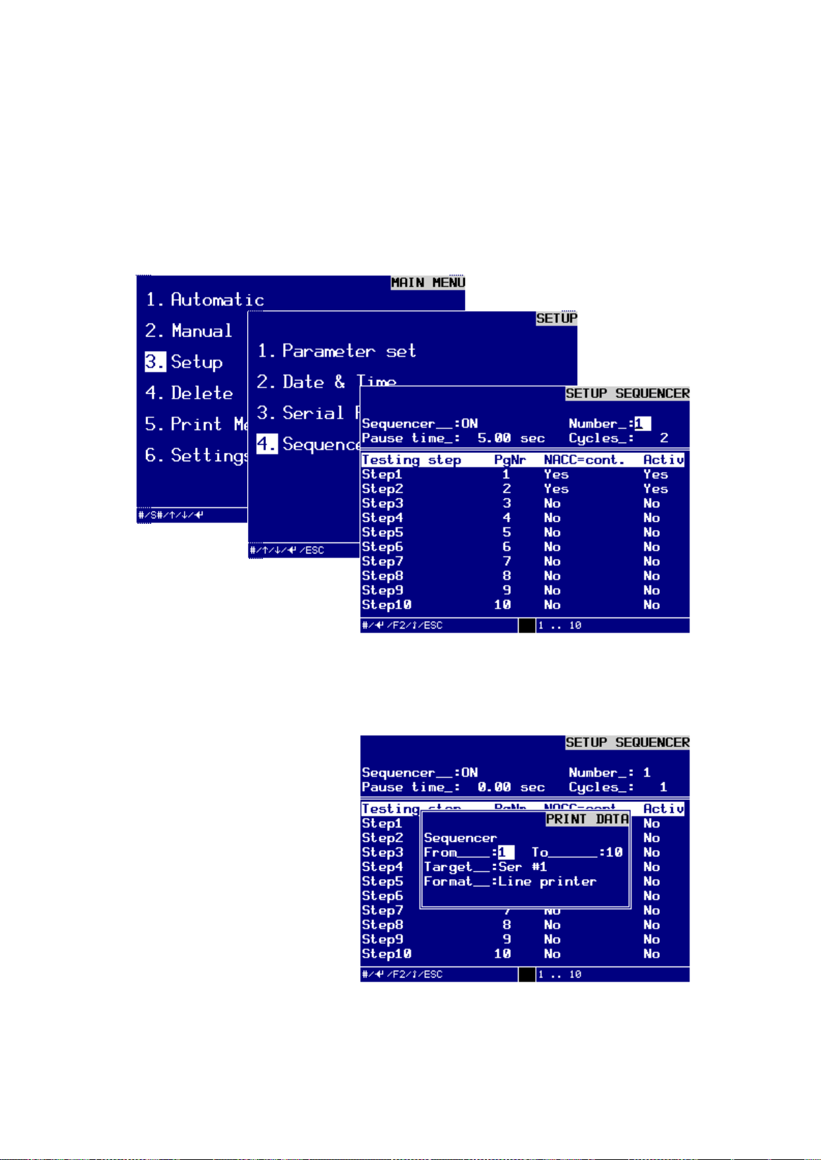
Command reference Menu 3. SETUP
79
4.1 Printout SEQUENCER PARAMETER
Here you can decide whether the program parameters should be shown on the display
or be printed out via an interface. Additional you can select which program parameters should be displayed or printed out.
In the MAIN MENU / 3. Setup you will find the dialog menu SETUP.
In the Menü SETUP / 1. Parameter set you can select the program number. The program parameters will be shown in the display.
Dialog window SET PARAMETER
Press key F2 to activate the dialog window PRINT DATA for data transfer via in-
terface.
On the display appears the window Print Data.
Set Parameter – Print Data
from: / to:
Enter the range of previous program parameter you want to output into the text
EN 3925-0060 V207-00 MANUAL R03.doc
HeMaTech
Prüftechnik
Page 80

Menu 3. SETUP Command reference
80
NOTE!
With a data output to a USB stick or external hard drive a file will be
automatically generated. The file name consists of the serial number
and the ending SEQ.
e.g. 10100100.SEQ
If a file with same file name already exists, the file will be opened and
the data append to the file.
fields from: und to:, and confirm these individually with the ENTER-key.
Possible entries range from 1 … 10.
Target:
Press the keys – and + to determine the desired TARGET for the data output:
You can select between:
Ser #1,
Ser #2,
USB-Stick.
Confirm the selection by pressing the ENTER-key.
Format:
Press the keys – and + to determine the desired FROMAT for the data output:
You can select between:
LINE printer.
Confirm the selection by pressing the ENTER-key.
You can output the selected program parameter through the selected interface by
pressing the F2-key.
The message Print data is active! is display in the display.
Press the ESC-key to exit the menu.
EN 3925-0060 V207-00 MANUAL R03.doc
HeMaTech
Prüftechnik
Page 81
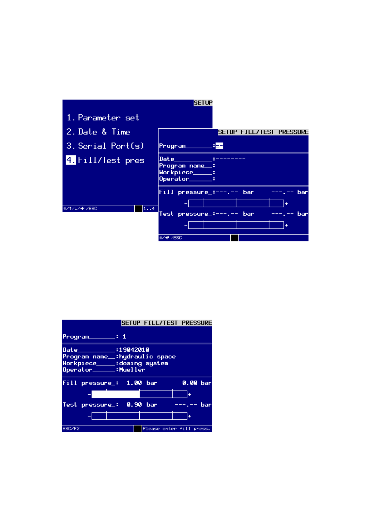
Command reference Menu 3. SETUP
81
5. Adjusting the filling/testing pressure manually (option 0050-04)
This optional menu can be opened from the dialog window SETUP FILLING
PRESSURE. It is used to set or change the filling and testing pressures for an already
existing program manually.
Dialog window SETUP FILLING/TESTING PRESSURE
To open the program in which you want to adjust the filling and testing pressures
manually:
enter the number of the desired program (in this example: 1) into the top line and
confirm the entry with the ENTER-key.
The program appears in the display and you can directly adjust the filling pressure.
Press F2 to toggle between the lines Filling pressure and Testing pressure.
Dialog window for manual adjustment of filling and testing pressure
EN 3925-0060 V207-00 MANUAL R03.doc
HeMaTech
Prüftechnik
Page 82
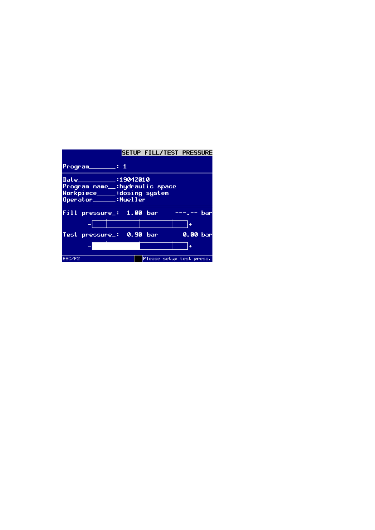
Menu 3. SETUP Command reference
82
Setting the filling pressure for a program manually
Make sure that "Filling pressure" is highlighted.
Keep changing the filling pressure controller, until the filling pressure indicator bar
is inside the tolerance range or corresponds with the nominal value.
Press the ESC-key to exit the menu.
If you want to adjust the testing pressure for the program, you must proceed as follows.
Setting the testing pressure for a program manually
Highlight "Testing pressure" by pressing the F2-key.
Dialog window for manual setting of testing pressure
Keep changing the testing pressure controller, until the testing pressure indicator
bar is inside the tolerance range or corresponds with the nominal value.
Press the ESC-key to exit the menu.
EN 3925-0060 V207-00 MANUAL R03.doc
HeMaTech
Prüftechnik
Page 83
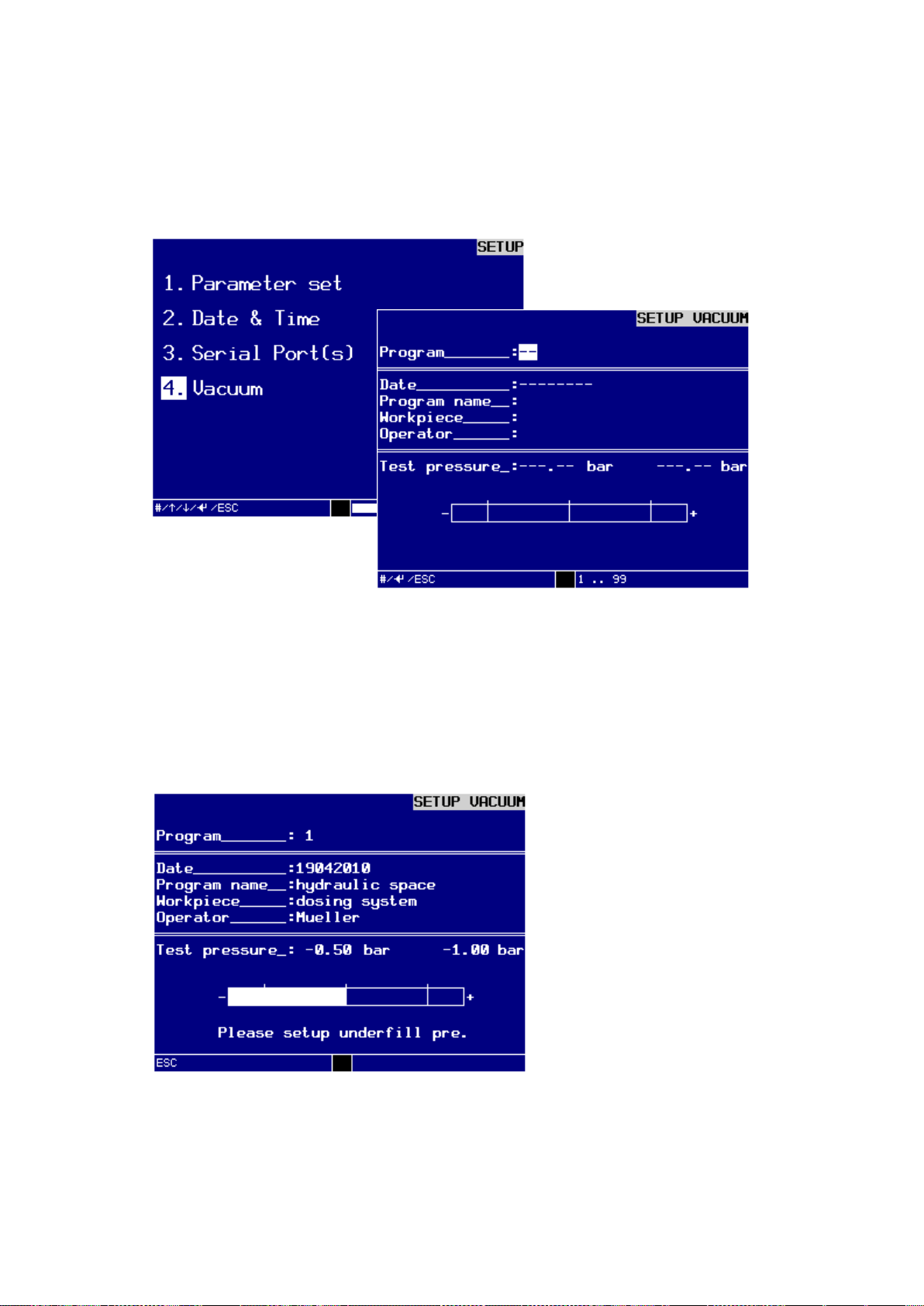
Command reference Menu 3. SETUP
83
6. Adjusting the vacuum manually (option 0050-01)
This optional menu can be opened from the dialog window SETUP/VACUUM. It is
used to set or change the vacuum testing pressures for an already existing program
manually.
Dialog window SETUP VACUUM
Adjusting the testing pressure (vacuum) manually
To open the program in which you want to adjust the vacuum testing pressures manu-
ally:
Enter the number of the desired program (in this example: 1) into the top line and
confirm the entry with the ENTER-key.
The test program appears in the display and you can directly adjust the testing pressure.
Setting the vacuum of the test program manually
Keep changing the testing pressure controller, until the testing pressure indicator
bar is inside the tolerance range or corresponds with the nominal value.
Press the ESC-key to exit the menu.
EN 3925-0060 V207-00 MANUAL R03.doc
HeMaTech
Prüftechnik
Page 84
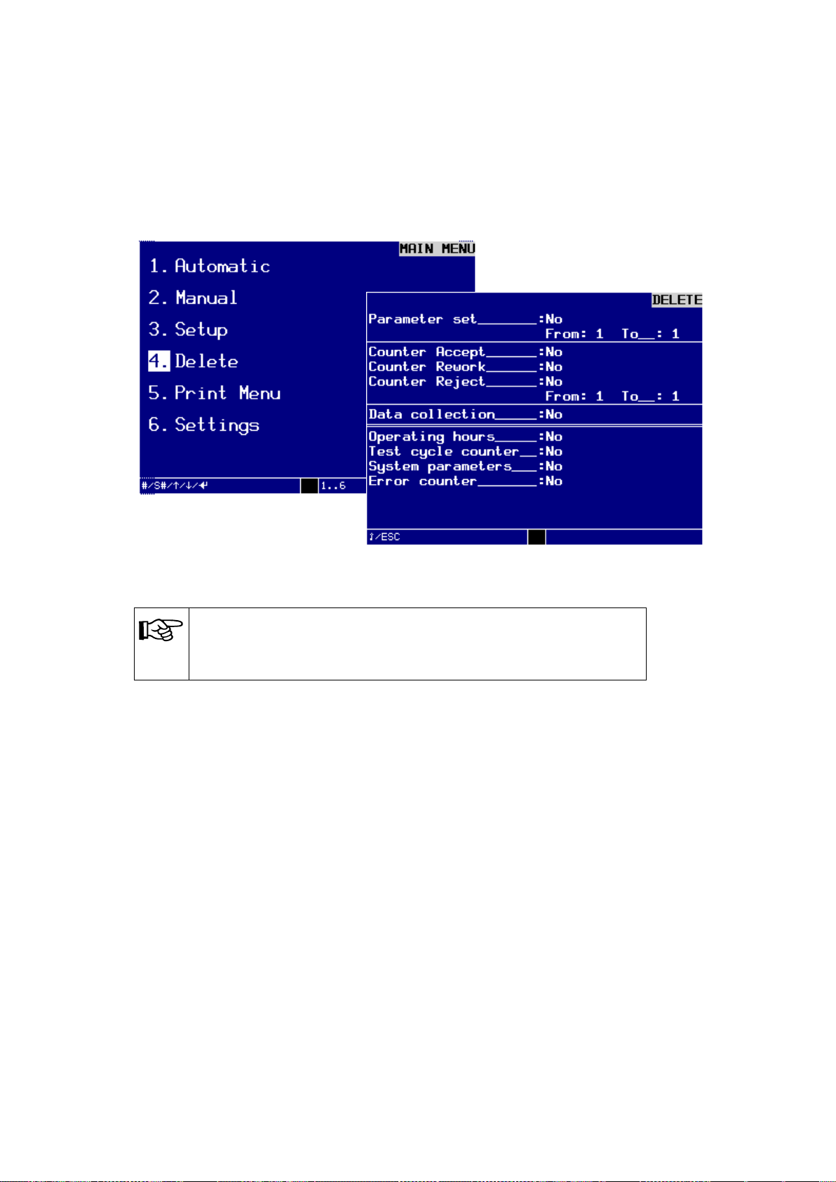
Menu 4. DELETE Command reference
84
NOTE!
Operating hours, test counter, system parameters and error counts
cannot be deleted by the operator.
Menu 4. DELETE
In the MAIN MENU / 4. Delete you find the dialog window DELETE. In this menu
you can delete data from the system, e.g. test programs, result memories and counters
for the results No Leak, Rework and Leak.
Dialog window DELETE
Turn key switch clockwise.
The write protection is disabled and you can start to delete the desired parameters.
Use the arrow keys to select the desired entries and press the keys – and + to tog-
gle between Yes to delete and No not to delete.
Specify the test programs from which you would like to delete these data by Edit
the corresponding program numbers into the text fields from: and to: and confirming these individually by pressing the ENTER-key.
The insertion point jumps to the next field.
Once you have made and checked all entries, you can delete the selected data.
Turn the key switch back to the vertical write protection position.
An audible signal will sound and the device will delete the data from the RAM
memory.
Press the ESC-key to exit the menu.
EN 3925-0060 V207-00 MANUAL R03.doc
HeMaTech
Prüftechnik
Page 85
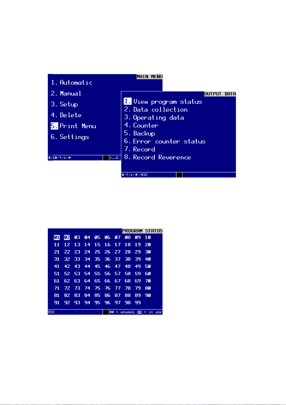
Command reference Menu 5. PRINT MENU
85
Menu 5. PRINT MENU
In the MAIN MENU / 5. Print Menu you find the dialog window OUTPUT DATA. In
this menu you can specify where the data should be transferred to.
Dialog window DATA OUTPUT
In the sub-menus you can determine the output of the different data:
1. View Program Status
In the dialog window PROGRAM STATUS you can view all program numbers, which
are already occupied, in the display. Program locations already used appear inversed.
Dialog window PROGRAM OVERVIEW
EN 3925-0060 V207-00 MANUAL R03.doc
HeMaTech
Prüftechnik
Page 86
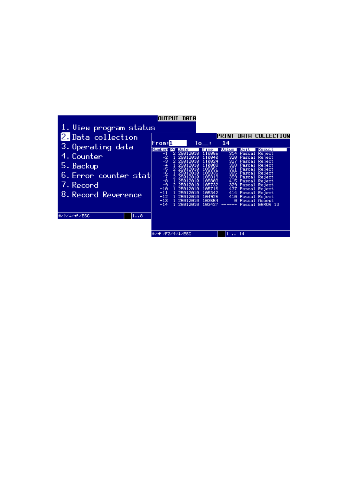
Menu 5. PRINT MENU Command reference
86
2. Data Collection
Here you specify whether the test results from the data collection are to be output on
the display or are to be transferred to a interface, and which results the output should
contain.
In the Menü OUPUT DATA / 2. Data collection you can select the range of data collection. The selected data collection will be shown in the display.
Dialog window DATA COLLECTION
from: / to:
Enter the range of previous date collection you want to output into the text fields
from: und to:, and confirm these entries with the ENTER-key.
Possible entries range from 1 … 7000 (depending on the memory size).
To confirm your input, press ENTER and the first 20 results will be shown in the
display.
You can press ENTER to view the next 20 results.
Press the key F2, to activate the dialog window PRINT DATA for data transfer via
interface.
On the display appears the window Print Data.
EN 3925-0060 V207-00 MANUAL R03.doc
HeMaTech
Prüftechnik
Page 87
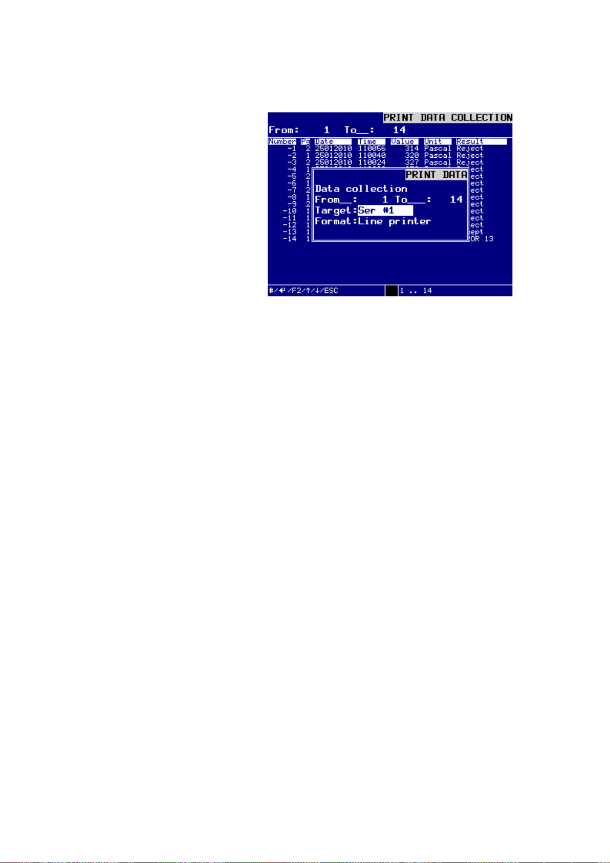
Command reference Menu 5. PRINT MENU
87
2.1 Print Data Collection
Dialog window – Print Data Collection
from: / to:
Enter the range of previous date collection you want to output into the text fields
from: und to:, and confirm these entries with the ENTER-key.
Possible entries range from 1 … 7000 (depending on the memory size).
Target:
Press the keys – and + to determine the desired TARGET for the data output:
You can select between:
Ser #1,
Ser #2 (optional),
USB-Stick.
Confirm the selection by pressing the ENTER-key.
Format:
Press the keys – and + to determine the desired FROMAT for the data output:
You can select between:
LINE printer.
Confirm the selection by pressing the ENTER-key.
You can output the selected program parameter through the selected interface by
pressing the F2-key.
The message Print data is active! is display in the display.
Press the ESC-key to exit the menu.
EN 3925-0060 V207-00 MANUAL R03.doc
HeMaTech
Prüftechnik
Page 88
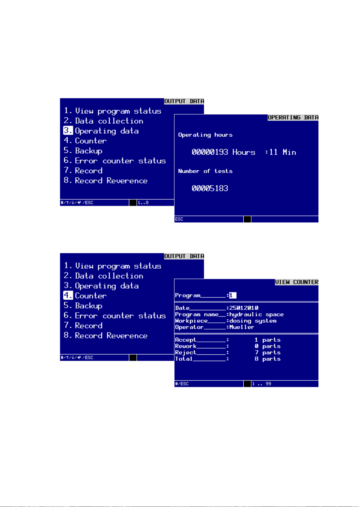
Menu 5. PRINT MENU Command reference
88
3. Operating data
Here you can view the complete operating hours and the number of all tests the test
device has performed.
Dialog window OPERATING DATA
Press the ESC-key to exit the menu.
4. Counter
Here you can view the data of the test program result counter on the display.
Dialog window VIEW COUNTER
Enter the number of the test program into the field Program: and press the
ENTER-key to confirm.
The result counters of the desired program are displayed.
Press the ESC-key to exit the menu.
EN 3925-0060 V207-00 MANUAL R03.doc
HeMaTech
Prüftechnik
Page 89
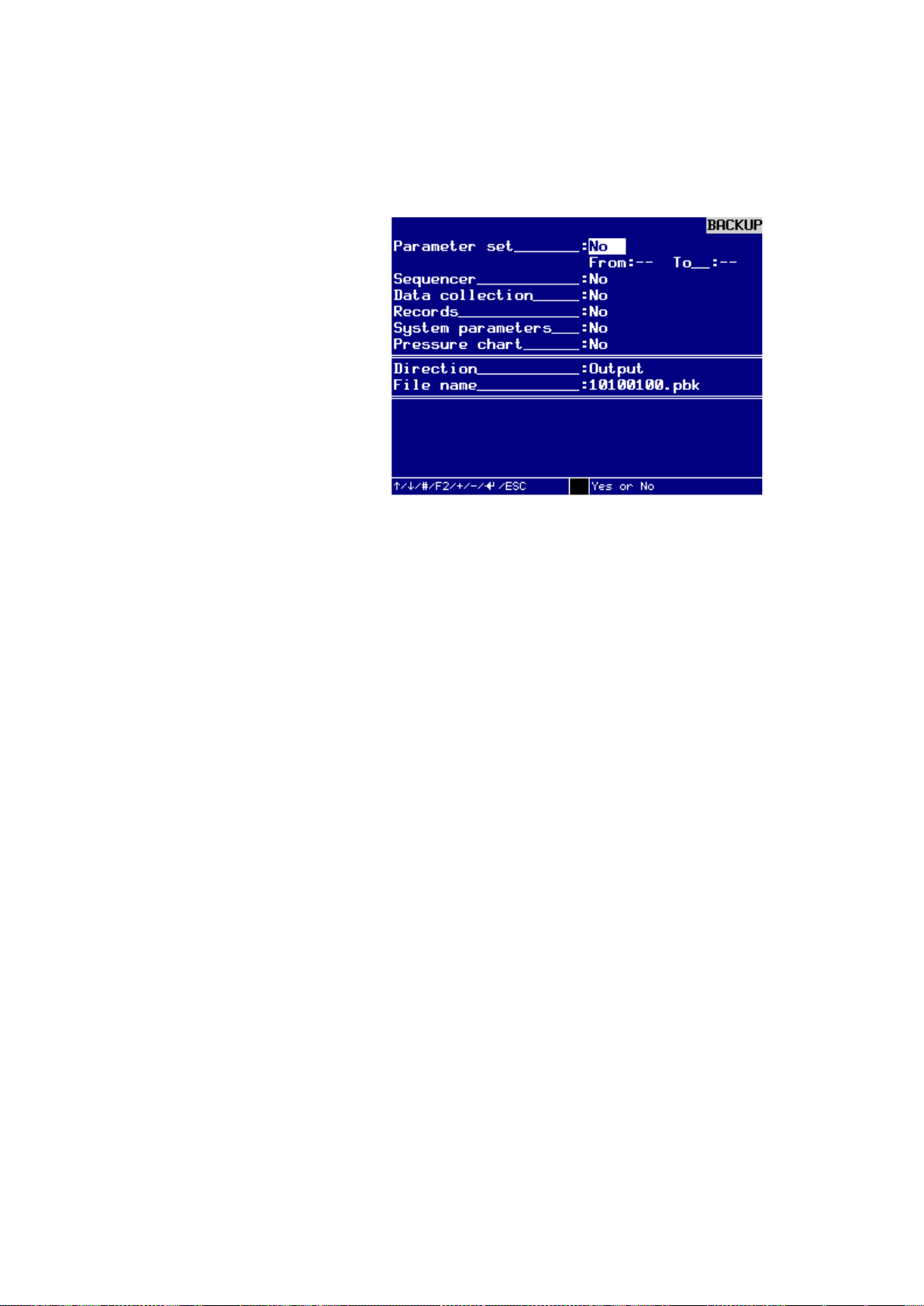
Command reference Menu 5. PRINT MENU
89
5. Backup
Here you can output or read in all data regarding the device, program and result data
via the USB interface.
Dialog window ERROR COUNTER STATUS
The concept of data backup is based on the register programming. This allows additional to the pure backup a editing of the data with a standard text editor. Since each
value by clearly defined by a register name and registration number, the values can
passed in any order.
To change the following values, just turn the key to the right, in horizontal position. If
you have choosen your backup parameters, just turn the key back in vertical position.
The Backup will start.
Parameter set_: YES/NO
You can use the buttons – and + to choose YES or NO. The proposed entry is NO.
From_: - Here you can select from which program number, the data will be stored. For selection
of the data being backed up, you can enter a test program number with digits from 1
... 99th. The proposed entry is 1.
To_: - Here you can select from which program number, the data will be stored. For selection
of the data being backed up, you can enter a test program number with digits from 1
... 99th. The proposed entry is 99.
Sequencer_: YES/NO
You can use the buttons – and + to choose YES or NO. The proposed entry is NO.
Data collection_: YES/NO
You can use the buttons – and + to choose YES or NO. The proposed entry is NO.
Records_: YES/NO
You can use the buttons – and + to choose YES or NO. The proposed entry is NO.
System parameters_: YES/NO
You can use the buttons – and + to choose YES or NO. The proposed entry is NO.
EN 3925-0060 V207-00 MANUAL R03.doc
HeMaTech
Prüftechnik
Page 90
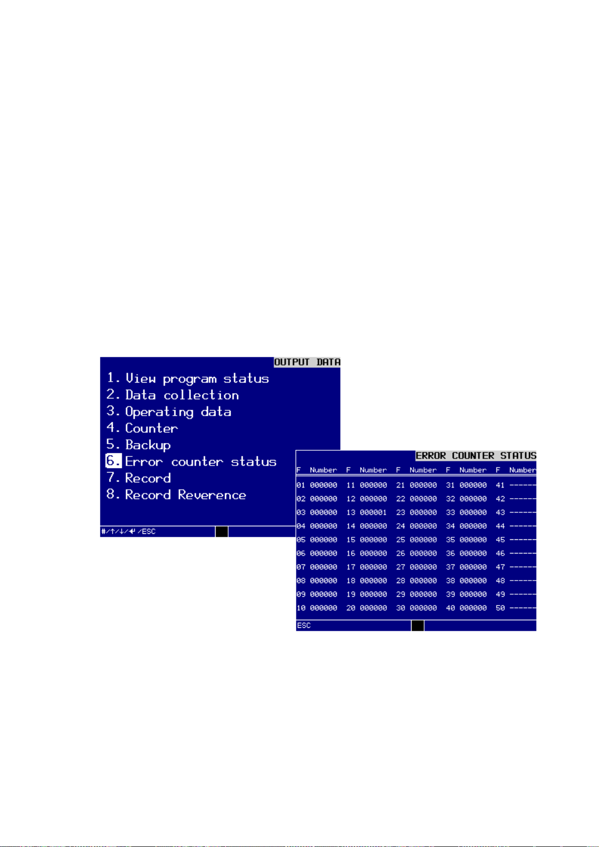
Menu 5. PRINT MENU Command reference
90
Pressure chart_: YES/NO
You can use the buttons – and + to choose YES or NO. The proposed entry is NO.
Direction_: - Here you can select the direction for data backup. You can use the buttons – and + to
choose Output or Input. The proposed entry is output.
Output to output the data.
Input to receive data.
File name_: - Here you can enter the file name for the backup. The file name can max. Be 8 charac-
ters long. The file extension .pbk is predefined for the file. The proposed entry is the
serial number of the device e.g. 10100100.
6. Error counter status
In this menu you can view the error counters on the display. Unoccupied error num-
bers are identified by dashes.
Dialog window ERROR COUNTER STATUS
EN 3925-0060 V207-00 MANUAL R03.doc
HeMaTech
Prüftechnik
Page 91
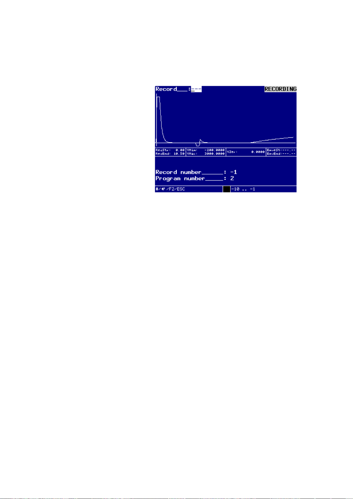
Command reference Menu 5. PRINT MENU
91
7. Record
In this menu you can view the recorded reference curve in the display.
Dialog window RECORDING
The output of the stored recording can be made.
Enter the number of the record into the field Record: and confirm the entered rec-
ord number with the ENTER-key.
The selected recording appears on the display.
Possible entries range is from -10 … -1.
The possible range is displayed dynamically in the help bar of the menu.
The stored recordings are chronologically reversed.
This means, -1 shows the recording of the last (most up-to-date) test process,
-2 the recording of the test process before this one, etc.
After the tenth test process the recording memory works as a loop memory and thus
the eleventh test will overwrite the recording of the first test.
If no recording is stored, no entries can be made.
Enter the number of the record into the field Record: and confirm the entered rec-
ord number with the ENTER-key.
The selected recording appears on the display.
Possible entries range is from -10 … -1.
The possible range is displayed dynamically in the help bar of the menu.
Press the ESC-key to exit the menu.
Press the key F2, to activate the dialog window PRINT DATA for data transfer via
interface.
On the display appears the window Print Data.
EN 3925-0060 V207-00 MANUAL R03.doc
HeMaTech
Prüftechnik
Page 92
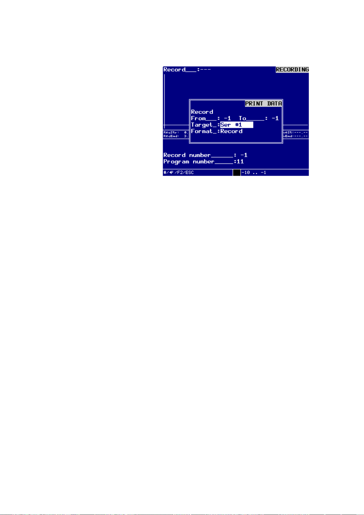
Menu 5. PRINT MENU Command reference
92
Dialog window – Print Recording
from: / to:
Enter the range of previous date collection you want to output into the text fields
from: und to:, and confirm these entries with the ENTER-key.
Possible entries range from -1 … -10.
Target:
Press the keys – and + to determine the desired TARGET for the data output:
You can select between:
Ser #1,
Ser #2 (optional),
USB-Stick.
Confirm the selection by pressing the ENTER-key.
Format:
Press the keys – and + to determine the desired FROMAT for the data output:
You can select between:
Record.
Confirm the selection by pressing the ENTER-key.
You can output the selected recording via the selected interface by pressing the
F2-key.
The message Print data is active! is display in the display.
Press the ESC-key to exit the menu.
EN 3925-0060 V207-00 MANUAL R03.doc
HeMaTech
Prüftechnik
Page 93
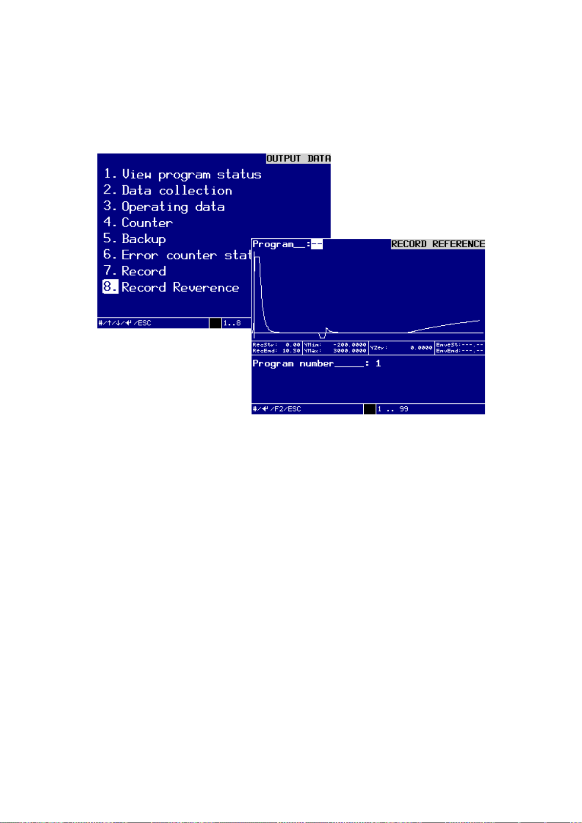
Command reference Menu 5. PRINT MENU
93
8. Record Reverence
In this menu you can view the last 10 saved filling curves on the display.
Dialog windows FILLING CURVES
Here you can output of the saved record reference.
Enter the number of the program into the field Program: and confirm the entered
program number with the ENTER-key.
The selected recording appears on the display.
Possible entries range is from 1 … 99.
Press the ESC-key to exit the menu.
Press the key F2, to activate the dialog window PRINT DATA for data transfer via
interface.
On the display appears the window Print Data.
EN 3925-0060 V207-00 MANUAL R03.doc
HeMaTech
Prüftechnik
Page 94
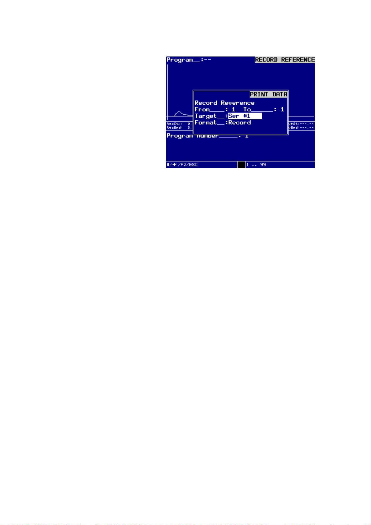
Menu 5. PRINT MENU Command reference
94
Dialog window – Print Recordi Reference
from: / to:
Enter the range of previous date collection you want to output into the text fields
from: und to:, and confirm these entries with the ENTER-key.
Possible entries range from 1 … 99.
Target:
Press the keys – and + to determine the desired TARGET for the data output:
You can select between:
Ser #1,
Ser #2 (optional),
USB-Stick.
Confirm the selection by pressing the ENTER-key.
Format:
Press the keys – and + to determine the desired FROMAT for the data output:
You can select between:
Record.
Confirm the selection by pressing the ENTER-key.
You can output the selected recording via the selected interface by pressing the
F2-key.
The message Print data is active! is display in the display.
Press the ESC-key to exit the menu.
EN 3925-0060 V207-00 MANUAL R03.doc
HeMaTech
Prüftechnik
Page 95
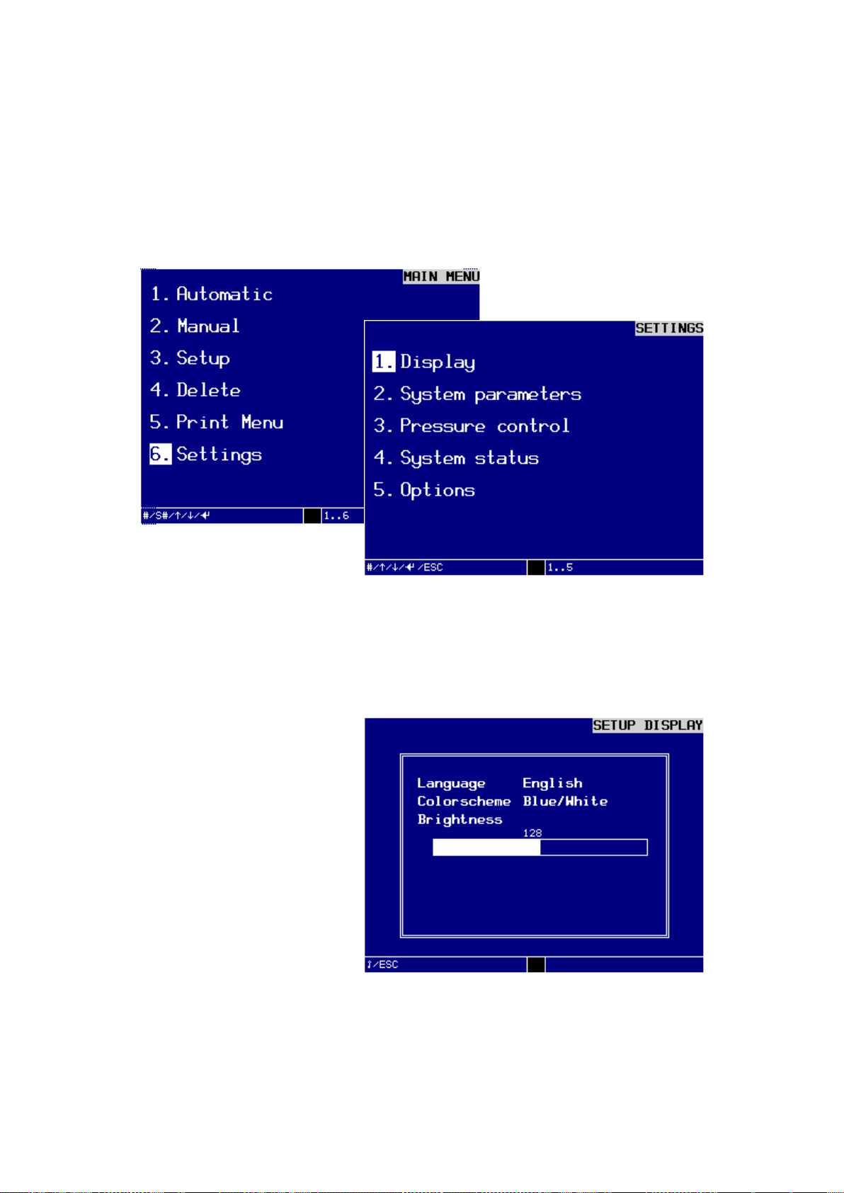
Command reference Menu 6. SETTINGS
95
Menu 6. SETTINGS
In the MAIN MENU/ 6. Settings you find SETTINGS.
In this menu you can set the display, view and output system parameters, change the
pressure control, view the input and output signals and set the switch-on masks and
the machine control.
Dialog window SETTINGS
You can make the individual settings in the sub-menus:
1. Display
In this dialog window you can make the necessary display settings like language,
mode, brightness and contrast.
Dialog window SETUP DISPLAY
Turn key switch clockwise.
The write protection is disabled and you can start with the settings.
Press the keys – or + to select the desired setting and press ENTER to confirm.
The insertion point jumps to the next subject.
EN 3925-0060 V207-00 MANUAL R03.doc
HeMaTech
Prüftechnik
Page 96

Menu 6. SETTINGS Command reference
96
Language
Here you select the language for the text display.
Mode
Here you specify the appearance of the display:
− black text on white background (standard)
− white text on black background (inverse)
Brightness
Here you can make the display lighter or darker. The corresponding brightness value
is represented by the bar with numbers ranging from 0 … 255.
Changes are directly visible on the display.
Contrast
Here you can change the contrast of the display. The corresponding contrast value is
represented by the bar with numbers ranging from 0 … 255.
Changes are directly visible when changing.
Make sure you have made all necessary settings.
Turn the key switch back to the vertical write protection position.
An audible signal will sound and the device saves the changed data to the RAM
memory.
Press the ESC-key to exit the menu.
EN 3925-0060 V207-00 MANUAL R03.doc
HeMaTech
Prüftechnik
Page 97
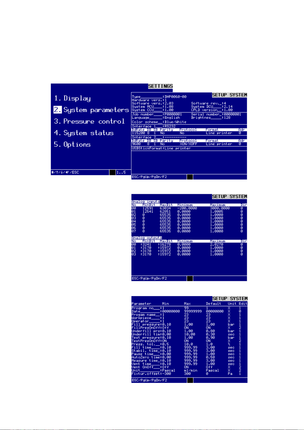
Command reference Menu 6. SETTINGS
97
2. System parameters
In this menu you can view the settings of all system parameters and output these
through the interface Ser #1.
Press key or to scroll through the following five pages:
The first dialog window SETTING SYSTEM
The second dialog window SETTING SYSTEM
The third dialog window SETTING SYSTEM
EN 3925-0060 V207-00 MANUAL R03.doc
HeMaTech
Prüftechnik
Page 98
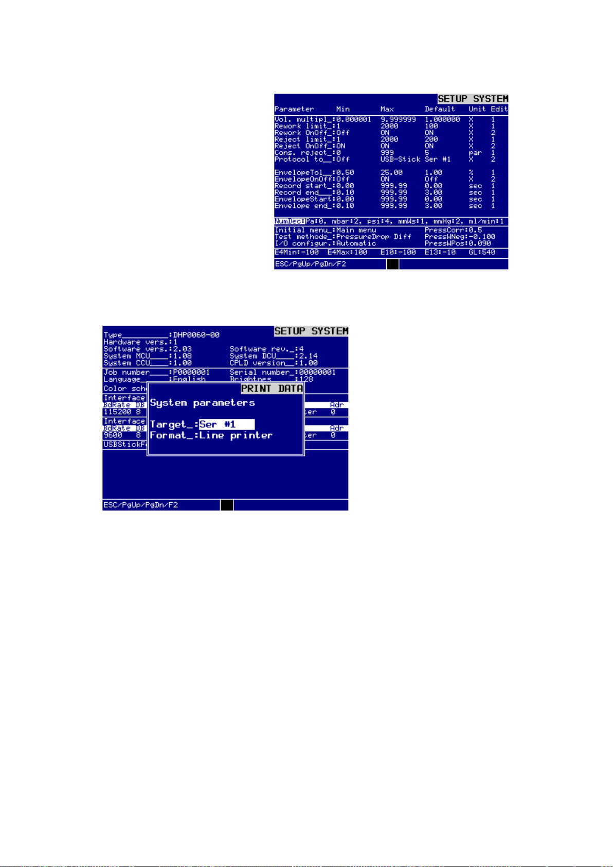
Menu 6. SETTINGS Command reference
98
The fourth dialog window SETTING SYSTEM
Press key F2 to output the system parameters via interface .
The dialog window SETTING SYSTEM – PRINT DATA
Press the ESC-key to exit the menu.
EN 3925-0060 V207-00 MANUAL R03.doc
HeMaTech
Prüftechnik
Page 99
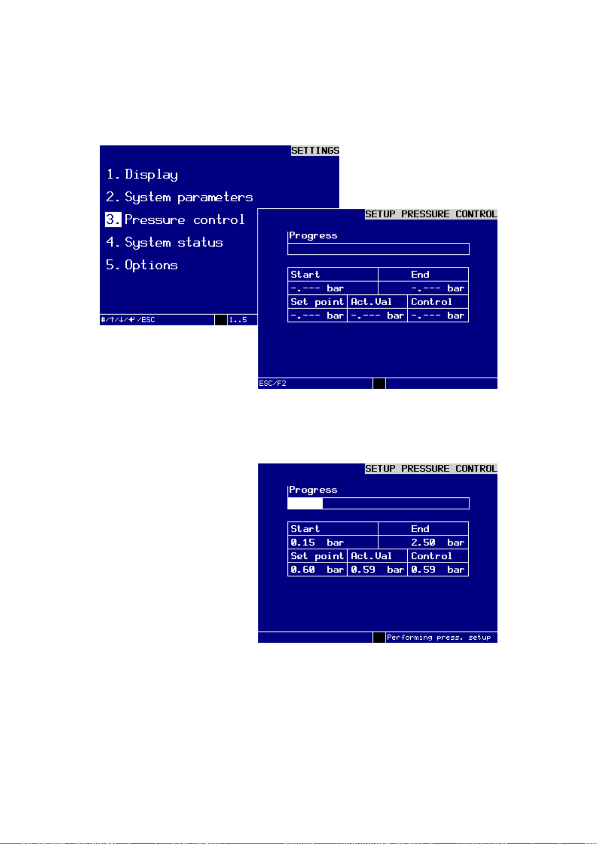
Command reference Menu 6. SETTINGS
99
3. Pressure control
In this menu you can redetect the settings for the pressure control
(electronic pressure control).
Dialog window SETUP PRESSURE CONTROL before start
Press key F2 to redetect the parameters for the pressure system.
This process takes a few minutes.
You can follow the sequence by the progress bar.
Dialog window SETUP PRESSURE SYSTEM during detection
Once the test device has determined the parameters for the pressure system, the device is reset and rebooted.
After the boot process the display will show the dialog window specified under
EN 3925-0060 V207-00 MANUAL R03.doc
HeMaTech
Prüftechnik
Page 100
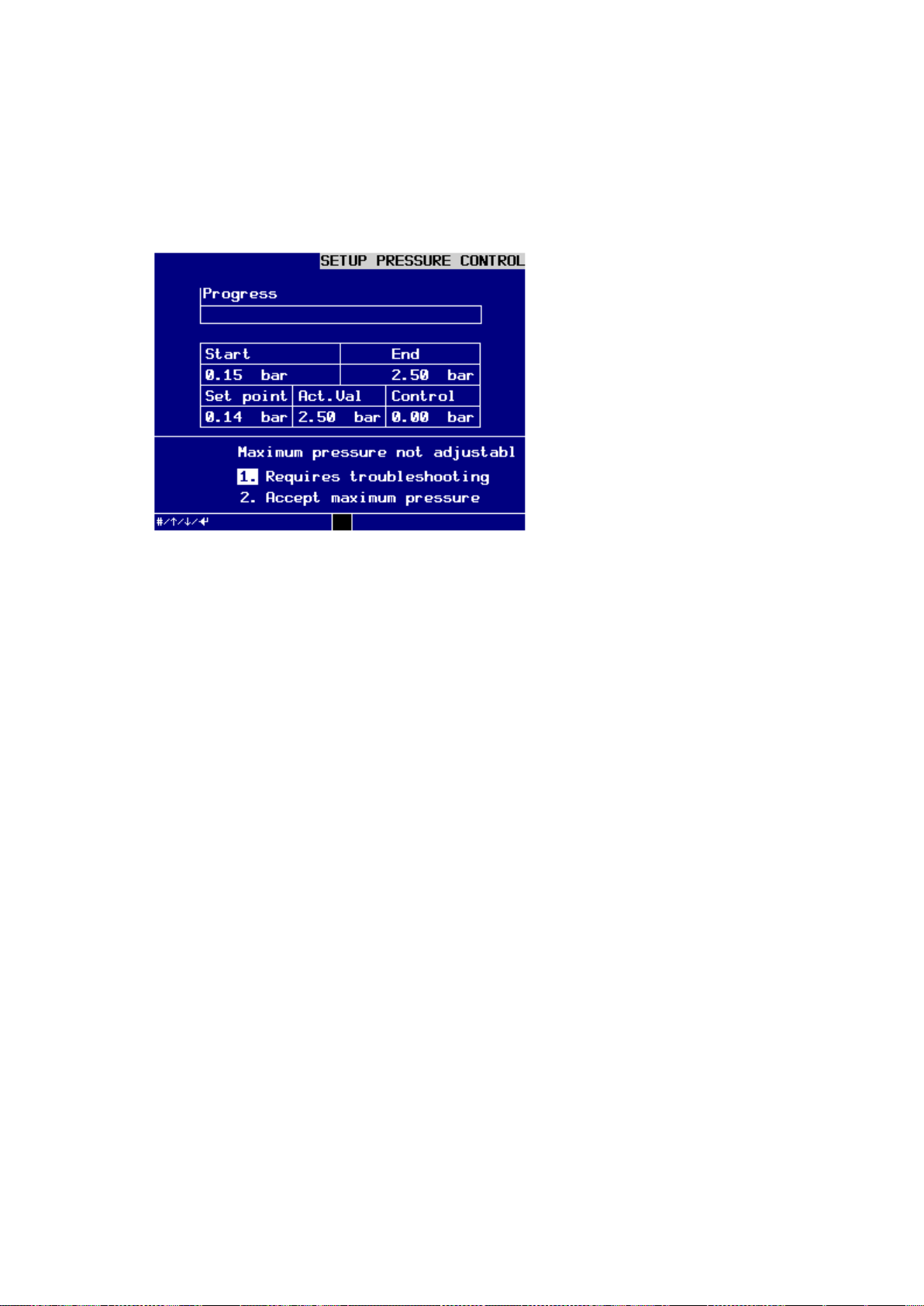
Menu 6. SETTINGS Command reference
100
Error in pressure detection
If there should be problems with the pressure detection, the following dialog window
will appear:
Dialog window SETUP PRESSURE CONTROL WINDOW with error message
This dialog window offers two possibilities to respond to this error message:
− Eliminate the cause of the fault.
Further information can be found under position 27 of the
chart
in chapter
Maintenance
.
Trouble shooting
− Accept maximum pressure.
The system determines the pressure table new up to the currently possible
maximum pressure. If higher pressure than the determined maximum pressure
is programmed during setup, the tester will submit the error 28
sure out of range
Maintenance
. In this case refer to the
.
Trouble shooting chart
Nominal pres-
in chapter
EN 3925-0060 V207-00 MANUAL R03.doc
HeMaTech
Prüftechnik
 Loading...