

Page 1
P e o p l e | I n n o v a t i o n s | S o l u t i o n s
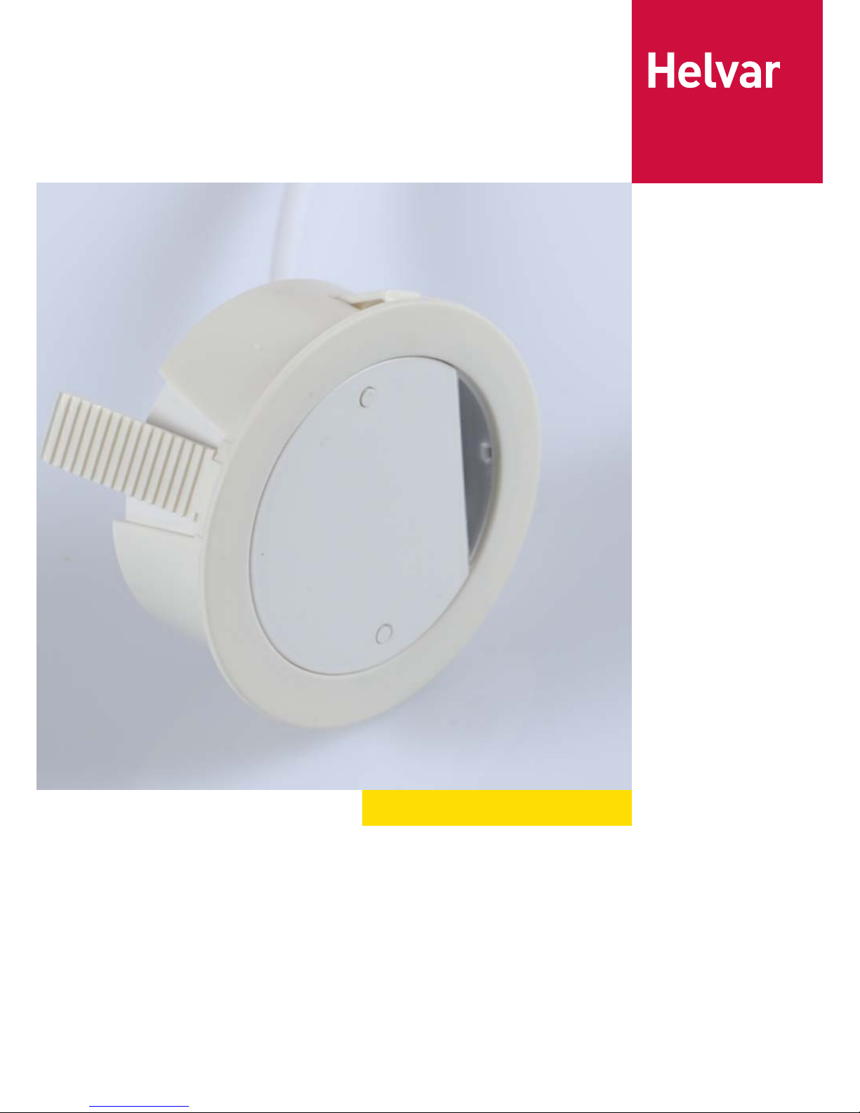
µDim Microwave Sensors User Manual
Page 2
2
µDim
1. Introduction
Doc No: T13 144 1C
Data is subject to change without notice. More information at: www.helvar.com
µDim Microwave Sensors
The µDim series of miniature microwave presence detectors provide automatic control of lighting loads with optional manual control. The unit comes
complete with a selection of fixing clips, allowing unobtrusive flush mounting of the sensor head into ceiling tiles or on to solid surfaces. It has been
designed so that it can be used for ceiling mounted or wall mounted applications. As microwave radiation penetrates plastic and glass, this unit has
been specifically designed to be mounted inside a luminaire.
Three versions are available: switched, 1-10V analogue, and DALI. All of which will switch incandescent, fluorescent and compact fluorescent
lighting.
The unit detects movement using a microwave sensor and turns the load on. When an area is no longer occupied the load will switch off after an
adjustable time out period has elapsed.
Table of Contents Page
Introduction 2
Technical data 3
Dimensions and mounting options 9
Connections 10
Setup 11
Programmming 12
Fault finding 14
Feature SL-MW-SW SL-MW-AN SL-MW-DA
Up to 8m microwave sensing
Lux sensor
Presence detection
Infrared remote setting
Relay output
1-10 V Dimming output - -
DALI Dimming output - -
Page 3
3
µDim
2. Technical Data
Doc No: T13 144 1C
Data is subject to change without notice. More information at: www.helvar.com
SL-MW-SW µDim Microwave Switching Sensor
The SL-MW-SW miniature microwave presence detector
provides automatic control of lighting loads. The unit comes
complete with a flush-mount bracket, allowing unobtrusive
mounting of the sensor head into ceiling tiles or onto solid
surfaces. It has been designed so that it can be used for
luminaire mounted or ceiling mounted applications. As
microwave radiation penetrates plastic and glass, this unit has
been specifically designed to be mounted inside a luminaire.
The product consists of the following :
• Sensor head with integral RJ11 sensor lead
• Power supply unit
• Flush mount bracket
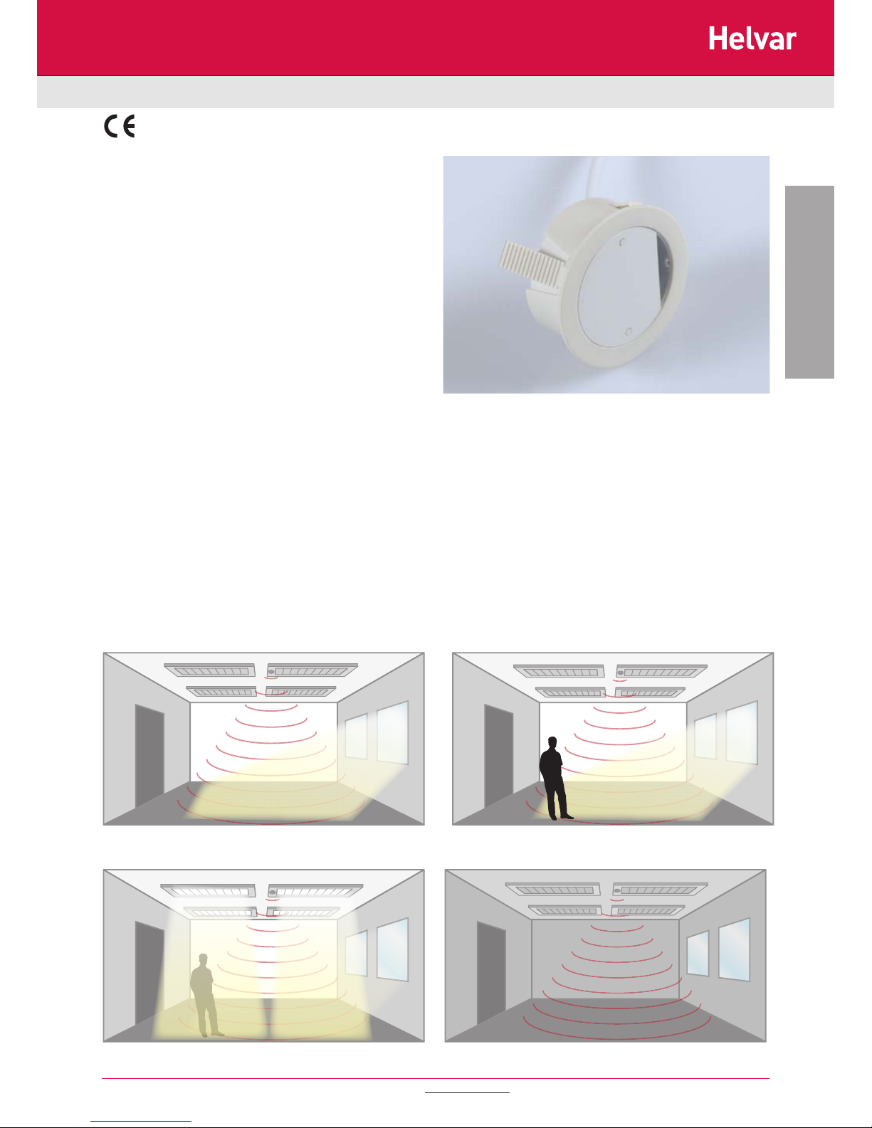
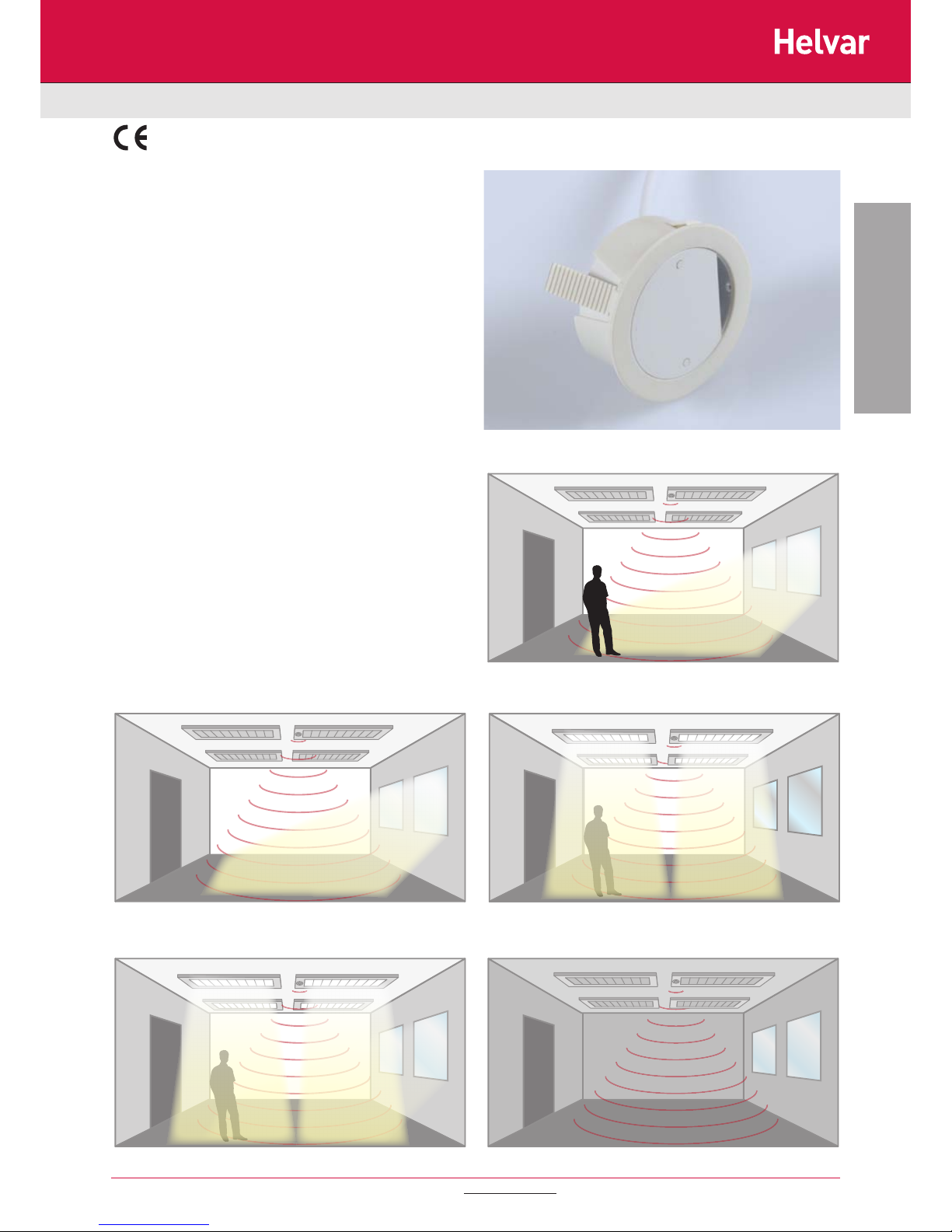
Presence detection: when movement is detected the load will
automatically turn on; when the area is no longer occupied the
load will automatically switch off after an adjustable time period.
1) No presence detected, daylight, lights OFF
3) Presence detected, insufficient daylight, lights ON 4) No presence detected, night time, lights OFF
2) Presence detected,sufficient daylight, lights OFF
Page 4
4
µDim
2. Technical Data
Doc No: T13 144 1C
Data is subject to change without notice. More information at: www.helvar.com
SL-MW-SW µDim Microwave Switching Sensor
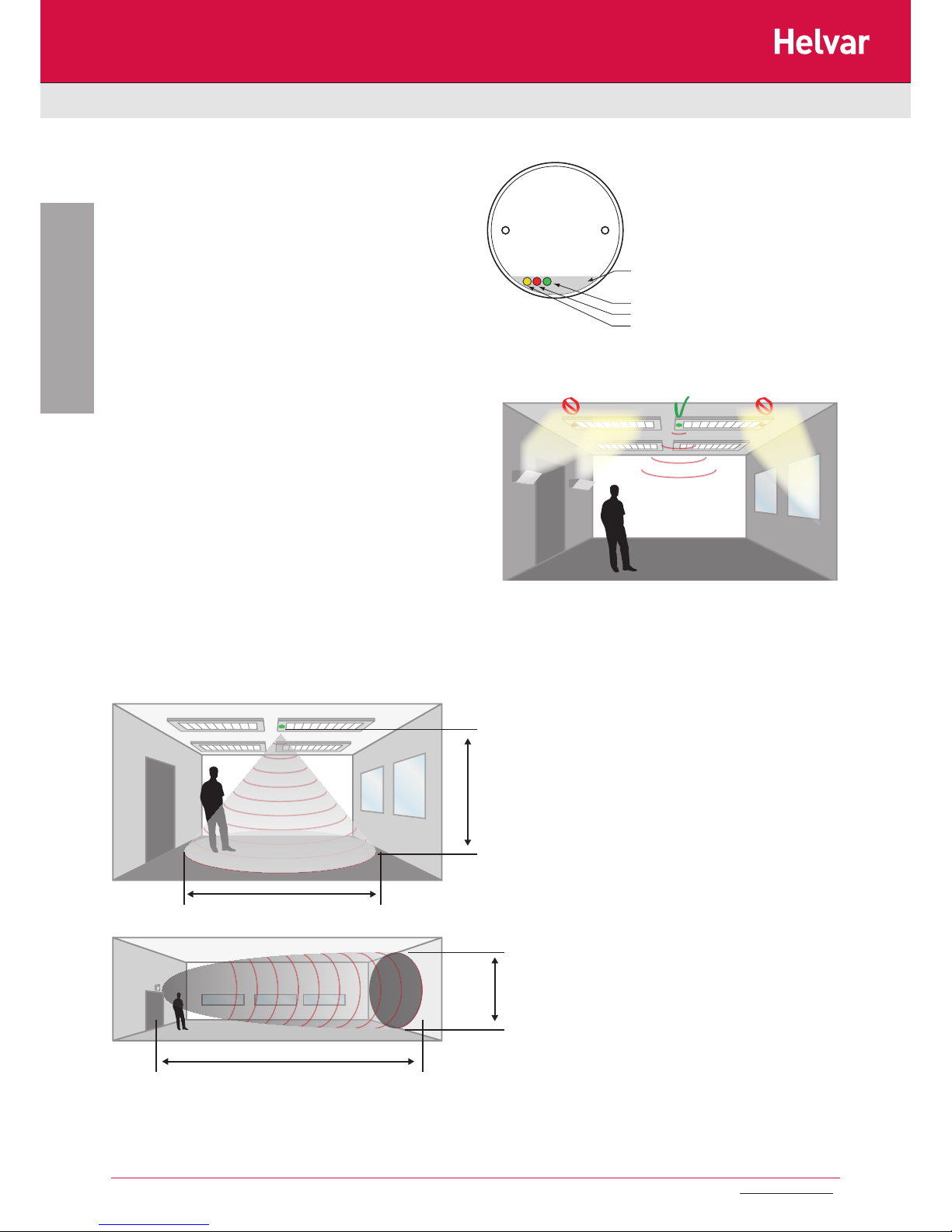
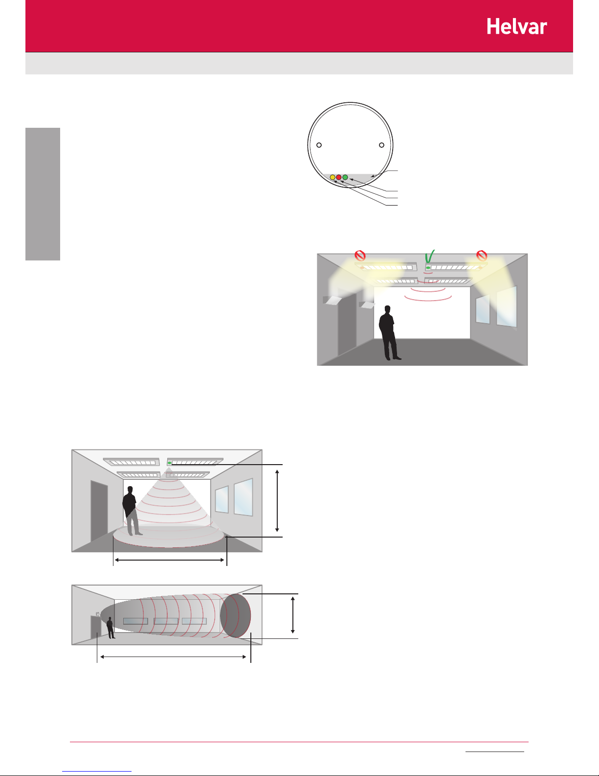
5m
12m
8m
2.8m
Recommended mounting location
Detection area
Sensor head
• Avoid direct sunlight entering the sensor
• Do not site within 1m of forced air heating or ventilation.
• Do not fix to a vibrating surface.
• Avoid metallic objects directly in front of the sensor head.
• Do not fit to a suspended luminaire
• When installing the sensor head behind a glass /
polycarbonate diffuser will reduce the detection range by
approximately 20%.
Note: On maximum sensitivity, the detector unit is extremely sensitive
to movement and may detect through glass, thin walls or partitions.
If this causes a problem, reduce its sensitivity using the SA-IR-PROG
Programmer.
Technical specifications
• Supply voltage 220 - 240 V AC, 50 Hz
• Max load capacity 2 A
• Light level Light to dark
• Connections Integral RJ11 cable between
supply unit and sensor head
• Terminals (supply unit) 1.5mm
2
(solid core cable only)
Material
• Sensor head, surface mount baseplate ,
flush bracket — Flame retardant ABS
• Flange mount bracket & Lens—PMMA (Clear acrylic)
• Power supply unit housing — Flame retardant polycarbonate
• Type Class 2
• Operating Temperature -10°C to 50°C
SAFETY
The microwave radiation emitted by these units is extremely
low power. At a distance of > 50mm the power density is <6%
of the ANSI IEEE C95.1 –1991 recommended microwave
power density. At a distance of 5mm from the unit it is <84% of
recommended power density.
Conformity EMC-89/336/EEC
LVD-73/23/EEC
Lens
Green LED - time
Red LED - lux / presence setting indicator
Yellow LED - sensitivity / absence setting indicator
Page 5
5
µDim
2. Technical Data
Doc No: T13 144 1C
Data is subject to change without notice. More information at: www.helvar.com
SL-MW-AN µDim Microwave 1-10V Sensor
The SL-MW-AN miniature microwave presence detector provides
automatic control of lighting loads. The unit comes complete
with a flush-mount bracket, allowing unobtrusive mounting of
the sensor head into ceiling tiles or onto solid surfaces. It has
been designed so that it can be used for luminaire mounted or
ceiling mounted applications. As microwave radiation penetrates
plastic and glass, this unit has been specifically designed to be
mounted inside a luminaire.
The product consists of the following :
• Sensor head with integral RJ11 sensor lead
• Power supply unit
• Flush mount bracket
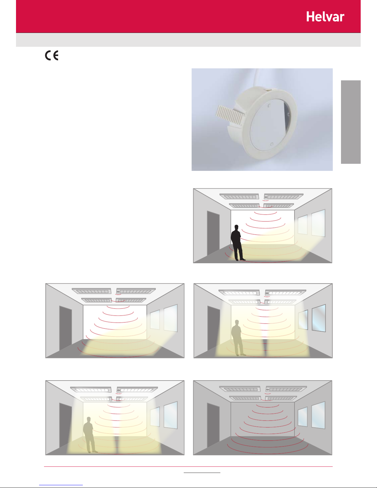
Presence detection: when movement is detected the load will
automatically turn on; when the area is no longer occupied the
load will automatically switch off after an adjustable time period.
1) No presence detected, daylight, lights OFF 4) Presence detected, insufficient daylight. Detector measures
and implements maintained illumininance
3) Presence detected some daylight.
Lights on and dimmed to maintain lux level
5) No presence detected, night time, lights OFF2) Presence detected,sufficient daylight, lights OFF
Page 6
6
µDim
2. Technical Data
Doc No: T13 144 1C
Data is subject to change without notice. More information at: www.helvar.com
SL-MW-AN µDim Microwave 1-10V Sensor
5m
12m
8m
2.8m
Recommended mounting location
Detection area
Sensor head
• Avoid direct sunlight entering the sensor
• Do not site within 1m of forced air heating or ventilation.
• Do not fix to a vibrating surface.
• Avoid metallic objects directly in front of the sensor head.
• Do not fit to a suspended luminaire
• When installing the sensor head behind a glass /
polycarbonate diffuser will reduce the detection range by
approximately 20%.
Note: On maximum sensitivity, the detector unit is extremely sensitive
to movement and may detect through glass, thin walls or partitions.
If this causes a problem, reduce its sensitivity using the SA-IR-PROG
Programmer.
•
Lens
Green LED - time
Red LED - lux / presence setting indicator
Yellow LED - sensitivity / absence setting indicator
Technical specifications
• Supply voltage 220 - 240 V AC, 50 Hz
• Max load capacity Relay Output - 2 A
Dimmed Output - 4 x 1-10V ballasts
• Light level Light to dark
• Connections Integral RJ11 cable between
supply unit and sensor head
• Terminals (supply unit) 1.5mm
2
(solid core cable only)
Material
• Sensor head, surface mount baseplate ,
flush bracket — Flame retardant ABS
• Flange mount bracket & Lens—PMMA (Clear acrylic)
• Power supply unit housing — Flame retardant polycarbonate
• Type Class 2
• Operating Temperature -10°C to 50°C
SAFETY
The microwave radiation emitted by these units is extremely
low power. At a distance of > 50mm the power density is <6%
of the ANSI IEEE C95.1 –1991 recommended microwave
power density. At a distance of 5mm from the unit it is <84% of
recommended power density.
Conformity EMC-89/336/EEC
LVD-73/23/EEC
Page 7
7
µDim
2. Technical Data
Doc No: T13 144 1C
Data is subject to change without notice. More information at: www.helvar.com
SL-MW-DA µDim Microwave DALI Sensor
The SL-MW-DA miniature microwave presence detector provides
automatic control of lighting loads. The unit comes complete
with a flush-mount bracket, allowing unobtrusive mounting of
the sensor head into ceiling tiles or onto solid surfaces. It has
been designed so that it can be used for luminaire mounted or
ceiling mounted applications. As microwave radiation penetrates
plastic and glass, this unit has been specifically designed to be
mounted inside a luminaire.
The product consists of the following :
• Sensor head with integral RJ11 sensor lead
• Power supply unit
• Flush mount bracket
Presence detection: when movement is detected the load will
automatically turn on; when the area is no longer occupied the
load will automatically switch off after an adjustable time period.
1) No presence detected, daylight, lights OFF 4) Presence detected, insufficient daylight. Detector measures
and implements maintained illumininance
3) Presence detected some daylight.
Lights on and dimmed to maintain lux level
5) No presence detected, night time, lights OFF2) Presence detected,sufficient daylight, lights OFF
Page 8
8
µDim
Doc No: T13 144 1C
2. Technical Data
Data is subject to change without notice. More information at: www.helvar.com
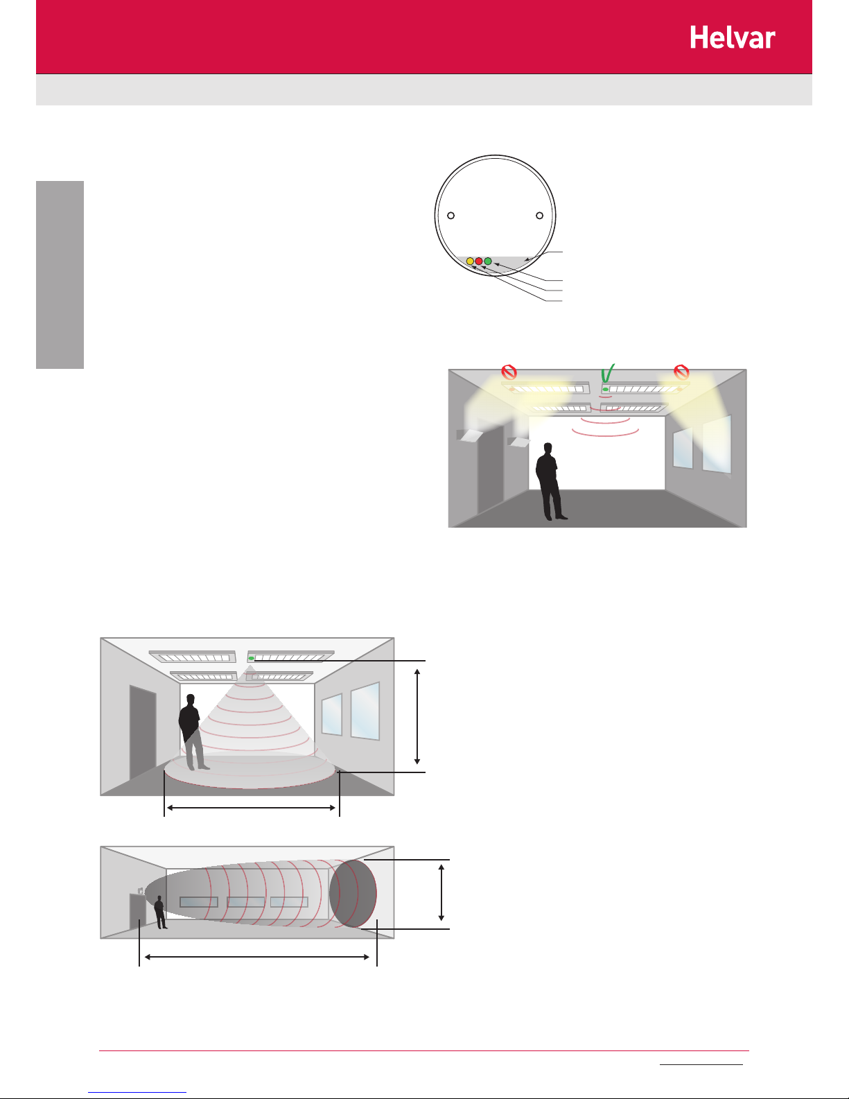
5m
12m
8m
2.8m
Recommended mounting location
Detection area
Sensor head
• Avoid direct sunlight entering the sensor
• Do not site within 1m of forced air heating or ventilation.
• Do not fix to a vibrating surface.
• Avoid metallic objects directly in front of the sensor head.
• Do not fit to a suspended luminaire
• When installing the sensor head behind a glass /
polycarbonate diffuser will reduce the detection range by
approximately 20%.
Note: On maximum sensitivity, the detector unit is extremely sensitive
to movement and may detect through glass, thin walls or partitions.
If this causes a problem, reduce its sensitivity using the SA-IR-PROG
Programmer.
Lens
Green LED - time
Red LED - lux / presence setting indicator
Yellow LED - sensitivity / absence setting indicator
SL-MW-DA µDim Microwave DALI Sensor
Technical specifications
• Supply voltage 220 - 240 V AC, 50 Hz
• Max load capacity Relay Output - 2 A
Dimmed Output - 4 x DALI ballasts
• Light level Light to dark
• Connections Integral RJ11 cable between
supply unit and sensor head
• Terminals (supply unit) 1.5mm
2
(solid core cable only)
Material
• Sensor head, surface mount baseplate ,
flush bracket — Flame retardant ABS
• Flange mount bracket & Lens—PMMA (Clear acrylic)
• Power supply unit housing — Flame retardant polycarbonate
• Type Class 2
• Operating Temperature -10°C to 50°C
SAFETY
The microwave radiation emitted by these units is extremely
low power. At a distance of > 50mm the power density is <6%
of the ANSI IEEE C95.1 –1991 recommended microwave
power density. At a distance of 5mm from the unit it is <84% of
recommended power density.
Conformity EMC-89/336/EEC
LVD-73/23/EEC
Page 9
9
µDim
3. Dimensions
Doc No: T13 144 1C
Data is subject to change without notice. More information at: www.helvar.com
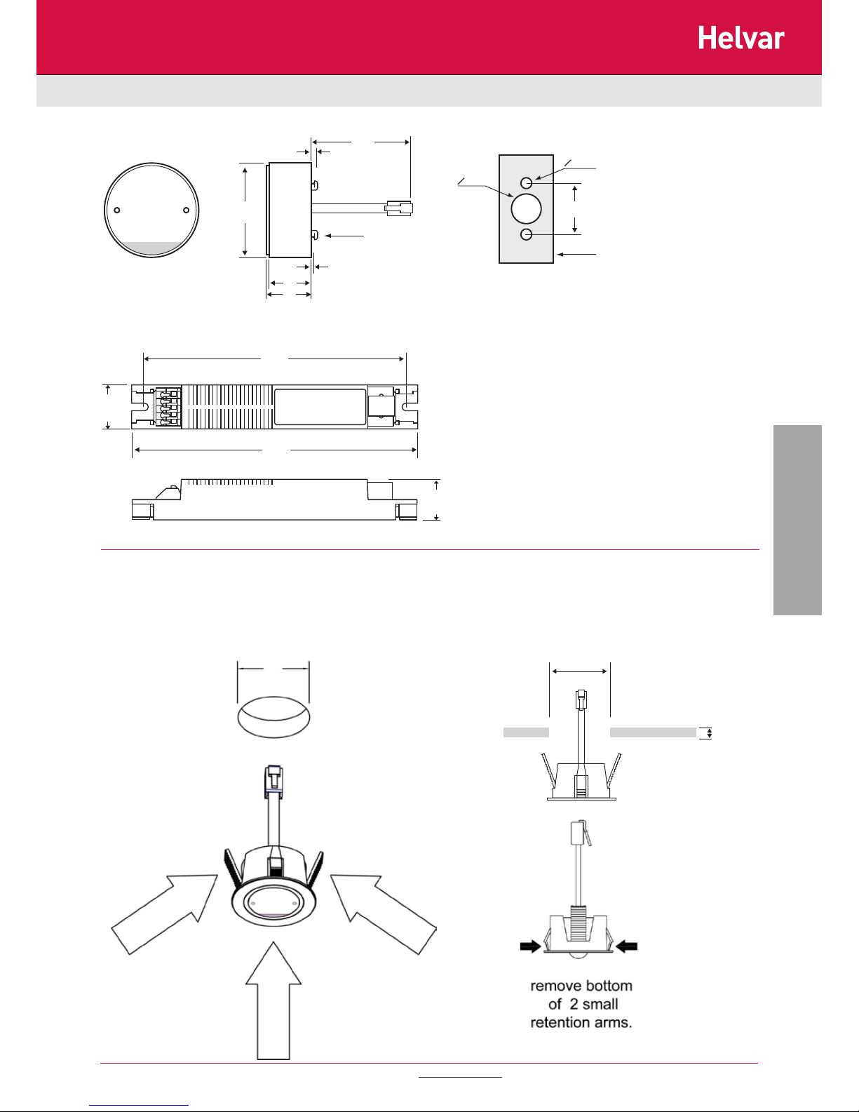
Dimensions & Mounting options
Flush mounting the sensor head using the flush mount bracket
Sensor head
Power supply unit
39
18
3
1.5
19
300
Fixing lugs for
bulkhead fitting
Details for using bulkhead fixing lugs
Bulkhead plate
max. thickness 1mm
o 4mm
o 11mm
19
22.5
20.5
133
145
44 mm
6 mm
The product can be mounted into a flat panel of a luminaire using the flush mount bracket as shown below. If flush mounting in a panel that is
greater than 6mm thick, remove bottom of retention arms with side cutters. A 44mm diameter hole will be required in the panel to mount the
flush mount bracket.
44
Page 10
10
4. Connections
µDim
Doc No: T13 144 1C
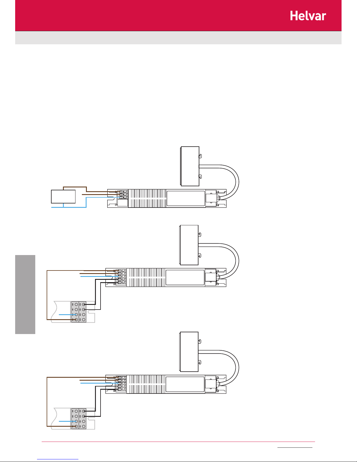
Connections
Sensor head
LOAD
max 2A
N
L
SL-MW-SW
Power supply unit
Sensor head
LOAD max 2A
N
L
1-10V
Ballast
C1(+)C0(-)
L
N
SL-MW-AN
Power supply unit
Sensor head
LOAD max 2A
N
L
DALI
Ballast
DA-DA+
L
N
SL-MW-DA
Power supply unit
• Connect the power supply via the terminal block on the power supply unit as shown overleaf. Live supply to the L terminal,
Neutral to the N terminal and the load to the LIVE OUT (L/out) terminal.
• Connect the sensor head to the power supply unit using the RJ11 connector, ensuring it “clicks” in place.
• In the case of dimming applications, connect the D+ and D_ connections to the corresponding terminals on the luminaire
dimming ballast.
• On power up, the load should come on immediately.
• Vacate the room or remain very still and wait for the load to switch off (on the factory preset, this should take approximately
15 minutes, but the timing out period can be adjusted down to 1 minute to help speed up the setup procedure — please
see next section for details on set-up & adjustment).
• Check that the load switches on when movement is detected.
Data is subject to change without notice. More information at: www.helvar.com
Page 11
11
5. Setup
µDim
Doc No: T13 144 1C
Setup
Positioning
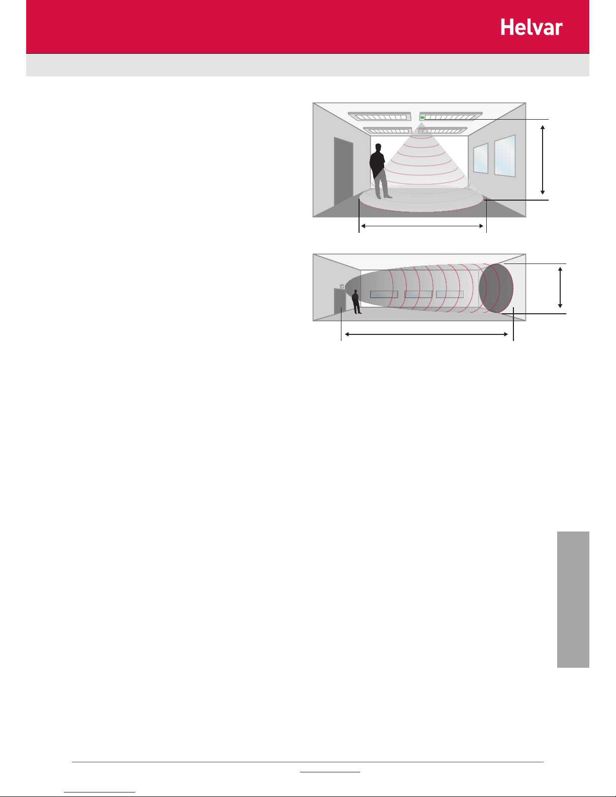
• The detector should be sited so that the occupants of the
room fall inside the detection pattern shown in picture. Please
note that when ceiling mounting, the recommended ceiling
height of the sensor head is 2.4m. Note that the lower the
sensor is installed the smaller the detection range will be,
subject to the parameters shown on the diagram.
• Avoid direct sunlight entering the sensor.
• Do not site within 1m of forced air heating or ventilation.
• Do not fix to a vibrating surface.
• Avoid metallic objects directly in front of the sensor head.
• Do not fit to a suspended luminaire.
Settings adjustment:-
• On initial power up, the factory set default settings are:-
• Time = 20 minutes.
• Lux = Maximum (i.e. lights will switch on in full daylight on
detection).
• Sensitivity = Maximum.
Time
All versions — set the time period using the programming handset (see
section 6). The factory default is 20 minutes.
Lux
SL-MW-SW — the switch level on lux setting determines the ambient
light level at which the lights turn on. This can be set using the
programming handset (see section 6). Setting to maximum (level 7)
ensures that lights always come on (this is also the default setting).
SL-MW-AN/DA — switch level on described above is available using
the programming handset only. The push button lux adjustment
determines the dimming output level and can be set using push button
the programming handset light level and works as follows:
• During operation the output level varies very gradually.
However when the level is changed the unit automatically
enters setup mode: in this mode the output level varies rapidly.
After the setup time the unit reverts to normal.
• When adjusting, allow the output level to settle by changing
very gradually.
• To disable the constant light function completely, set the level
to maximum.
Data is subject to change without notice. More information at: www.helvar.com
5m
12m
8m
2.8m
Page 12
12
Preset
functions
0 1 2 3 Description
Button Activation
On / Raise On Raise
Turn lights on or to raise lights .
Off / Lower Off Low er
Turn lights off or t o lower lights.
Walk tes t On Off
When s et to On this causes a red LED t o flash on the sens or
when it det ect s mov ement. Us e this f eature to check f or
adequate s ensit iv ity lev els.
Time Out
(Time
adjustment)
1, 10 &
20
minutes
5, 15 &
30
minutes
10
seconds
Once t he det ect or is t urned on, this v alue sets how long the
lights will st ay on once movement has ceas ed.
Lux on
level
(Switch
level on)
2, 5 & 7 4, 6 & 9
Lux lev el setting to prevent the lum inaires being s witched on if
the am bient light level is suffic ient (adjust able between 1
and 9). The luminaires will al way s be switc hed on at level 9.
Light Level 2 (200)
5 (500)
7 (700)
4 (400)
6 (600)
9 (900)
Sets a t arget light level to be m aintained by t he lighting syst em.
Lux off
level
(Switch
level off)
2, 5 & 7 4, 6 & 9
Lux lev el setting to switc h the lum inaires off during occ upancy if
the am bient light level goes above the setting (adjus table
between 1 and 9). Lev el 9 will alway s keep the lights on. This
sett ing c an be used for “window row s witching”.
Sensitivity 1, 5 & 9 3, 6 & 8
Sensitiv ity level for detecting mov ement .
1 = low s ensit iv ity
9 = high sens itiv ity
Defaults D
Returns t he unit to the def ault settings .
Burn-in
0 50 100
Determ ines how long t he out put will be at 100% s o that lamps
‘burn-in’. The ’b urn-in’ time is not aff ected by power s upply
interruptions .
Shift
Use this but ton to selec t the set tings in red and blue signif ied
by t he ‘Shif t 1’ and ‘Shift 2’ LEDs
Number of Shift key pr esses
SHIFT 1 SHIFT 2 SHIFT 1 SHIFT 2 SHIFT 1 SHIFT 2 SHIFT 1 SHIFT 2
µDim
6. Programming
Doc No: T13 144 1C
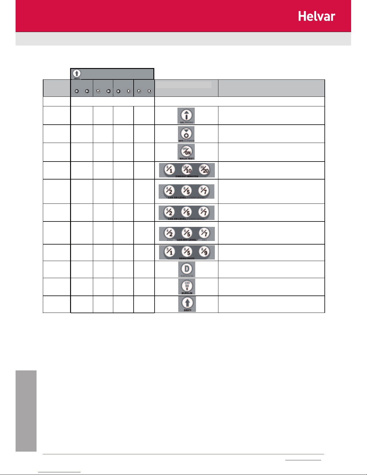
Programmer Graphics
All the following functions can be programmed using the SA-IR-PROG handset:
Data is subject to change without notice. More information at: www.helvar.com
Programming
Page 13

13
µDim
Doc No: T13 144 1C
Data is subject to change without notice. More information at: www.helvar.com
Page 14

14
µDim
Doc No: T13 144 1C
LOAD DOES NOT COME ON
Check to see if the live supply to the circuit is good. Strap across the L
and LIVE OUT (where used) terminal to turn the load on.
If the supply and wiring are good, check the LUX level setting. Increase
the LUX level setting to allow the controller to turn on at higher ambient
natural light level.
If the detection range is smaller than expected, check the diagram
above. Rotating the sensor slightly may improve the range.
LIGHTS DO NOT GO OFF
Ensure that the area is left unoccupied for longer than the selected timer
setting.
Make sure that the sensor is not adjacent to circulating air, heaters or
lamps.
If the unit “false triggers” reduce the sensitivity using the sensitivity
settings (see section 4 and 5).
Data is subject to change without notice. More information at: www.helvar.com
Fault finding
Part numbers
Helvar Oy Ab
Yrittäjäntie 23, P.O.Box 100
FI-03601 Karkkila
Finland
www.helvar.com
FI: +358 9 56 54 1
UK: +44 1322 222 211
SE: +46 8 545 239 70
FR: +33 1 3418 1281
IT: +39 02 55 30 10 33
DE: +49 6104 78075
RU: +7 (495) 728 82 91
HU: +36 1 2393 136
CN: + 86 512 6763 3078
Product: µDim Microwave sensors User Manual
Doc No. T13 144 1C
Issue 2
Product not to be used in the U.S.A.
SL-MW-SW Miniature PIR with switched (relay) output
SL-MW-AN Miniature PIR with 1-10V Analogue and switched (relay) output
SL-MW-DA Miniature PIR with DALI and switched (relay) output
Accessories
SA-IR-PROG IR programming handset
IMPORTANT NOTICE!
This device should be installed by a qualified
electrician in accordance with the latest
edition of the IEE wiring regulations.
 Loading...