

HELTUN HE-RS01 User Manual

RELAY SWITCH QUINTO
HE-RS01
USER MANUAL V1.0

Table of Contents
Overview......................................................................................................................................................................... 3
Technical Specicaons.................................................................................................................................................. 3
Funcons & Features...................................................................................................................................................... 4
Installaon...................................................................................................................................................................... 4
Disassembly.................................................................................................................................................................... 5
Operaon........................................................................................................................................................................ 6
Scenarios......................................................................................................................................................................... 6
Factory Reset (RES)......................................................................................................................................................... 6
Power and Energy Consumpon.....................................................................................................................................7
Z-Wave Network............................................................................................................................................................. 7
Adding HE-RS01 to a Z-Wave network....................................................................................................................... 7
Removing HE-RS01 from a Z-Wave network..............................................................................................................7
Security...................................................................................................................................................................... 8
SmartStart..................................................................................................................................................................8
Firmware OTA Update............................................................................................................................................... 8
Associaons............................................................................................................................................................... 8
Gateway Compability Requirement.......................................................................................................................10
Z-Wave Plus v2 Specicaons..................................................................................................................................10
HE-RS01 Se:ngs Using Z-Wave Protocol (Gateway)...............................................................................................11
Time Conguraon............................................................................................................................................. 11
Sensor Conguraon..........................................................................................................................................11
Limited Warranty..........................................................................................................................................................15
2

Overview
This is the user manual for the HELTUN HE-RS01 Advanced Programmable Relay Switch ‘Quinto’ (i.e. five-channel). It
is designed to fit inside standard round, square, or rectangular electrical junction boxes installed behind an existing inwall switch or inside a circuit breaker panel. Relay Switch Quinto enables On/Off controls of lights, dimmers, blinds,
doors, gates, valves, and motors either manually by a direct-connected switch, or remotely through a Z-Wave™
network.
Thanks to the HE-RS01 five-channel relays it can manage up to five On/Off devices, or three On/Off devices and one
two-direction motors, or one On/Off device and two two-direction motors. It has two independent inputs for relay
channels which allow it to control systems with different power sources or to use relay outputs as dry contacts. Each
relay can be loaded up to five amps and uses the HELTUN Advanced Zero-Cross Technology to increase the life of
the device and connected system.
The HE-RS01 can also be used to manage motorized systems; e.g. garage doors, window blinds, etc. It allows
association with relay switches and roller shutters to control the opening and closing of the system.
The HE-RS01 has an onboard Real Time Clock (RTC) that enables scenarios where connected devices can be
triggered on a schedule.
The HE-RS01 has five fully configurable inputs for external switches. Each input can be configured to control the relay
output state (from one to five) in any of nine different modes. The inputs also can be used to activate scenes on a ZWave Controller.
The HE-RS01 integrates a Z-Wave Plus™ v2 700 platform module allowing it to be used with Z-Wave home
automation systems. It supports Z-Wave ‘S0’ and ‘S2’ security protocols, SmartStart technology, and can be connected
(i.e. “associated”) with up to 15 other Z-Wave devices, such as relays, switches, dimmers, motor controllers, etc.
The HE-RS01 is also an excellent choice for managing lighting systems, allowing association to Z-Wave dimmers
controlling both On and Off—as well as smooth brighten (Up) and smooth dim (Down)—states using external switches
connected to HE-RS01 inputs.
Technical Specifications
Dimensions: 50mm (H) х 50mm (W) х 27mm (D)
Materials: Flame retardant plastic
LED indicator for device status
Five-channel relay outputs, resistive load up to 5A each
Two independent relays inputs, dry contact
Operating temperature: 0°С to 50°С
Power supply: 85-265VAC 50Hz/60Hz, or 24-48VDC
Power consumption: 1W
Active elements: Electromagnetic Relay Switch
Relay switching with HELTUN Advanced Zero-Cross Technology
Relay life: 100.000 switches
Device control
o Through Z-Wave network
o Directly with pilot wires
IP class: IP21
Z-Wave Plus V2 SDK: V7.11
Z-Wave module: ZGM130S
Requires mounting to flush electrical junction box:
round, square, or rectangular type – min. depth 40mm
3
Functions & Features
Options for Inclusion/Exclusion to/from Z-Wave network
o Non-Secure
o S0 Secure
o S2 Unauthorized, S2 Authorized with Key
Association control of 15 devices from the network
Schedule mode
Motorized device control (i.e. roller shutter mode)
Each of five external inputs can control any relay output
Up to five different relay channels can be controlled by one external input
Each external input can be set up to control devices from associated groups
Each external input & relay output can be managed by a gateway or associated device
Each external input can trigger scenes (i.e. acts like scene controller)
Any relay channel may be excluded from control
Nine modes available for each relay:
1. Switch-ON
2. Switch-OFF
3. Timer: ON>OFF
4. Timer Reversed: OFF>ON
5. Inverse
6. Two-Relay Inverse
7. Momentary
8. Momentary Reversed
9. Roller Shutter
Adjustable periodic measurements from:
o Energy consumption meter
Software energy consumption logic
Factory reset function
SmartStart technology for quick addition to Z-Wave networks
OTA (Over The Air) encrypted firmware update
Installation
HELTUN recommends the HE-RS01 relay switch be installed by a licensed electrician in a
manner that conforms to local regulations and building codes. Provide these instructions to the
licensed electrician who is installing the HE-RS01.
WARNING: Electrical power must be switched off during installation.
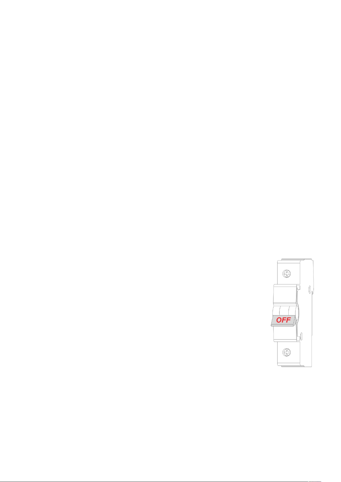
1. FIRST ENSURE THE POWER IS OFF at the main circuit breaker (Fig. 1), and then test the
wires with a probe or multimeter to verify.
2. Insert power wires into the HE-RS01 “POWER” terminals by inserting a small Phillips-head
screwdriver in the slot beneath each terminal and unscrew to open. Follow Fig. 2: Connection
Diagram and instructions below:
• Power wires: for AC power (85-265VAC) connect Line & Neutral lead wires to L & N
terminals labeled “POWER”. For DC power (24-48VDC) connect “+” wire to terminal L and “–”
wire to terminal N.
• Source 1 wire: connect the required power source for relays 1, 2, and 3 to the terminal
labeled “IN 1-3”.
• Source 2 wire: connect the required power source for relays 4 and 5 to the terminal labeled
“IN 4-5”.
• Loads: connect the required loads to the relay output terminals labeled “OUT-1”, “OUT-2”, “OUT-3”,
“OUT-4”, “OUT-5”.
Note: HELTUN recommends installing cord terminals (electric wire ferrules) on the ends of wires before connecting
them to the HE-RS01 outputs (various colors terminals are included).
Note: Zero-Cross technology is unavailable if the device uses DC voltage (24-48VDC).
4
Figure 1:
Circuit Breaker
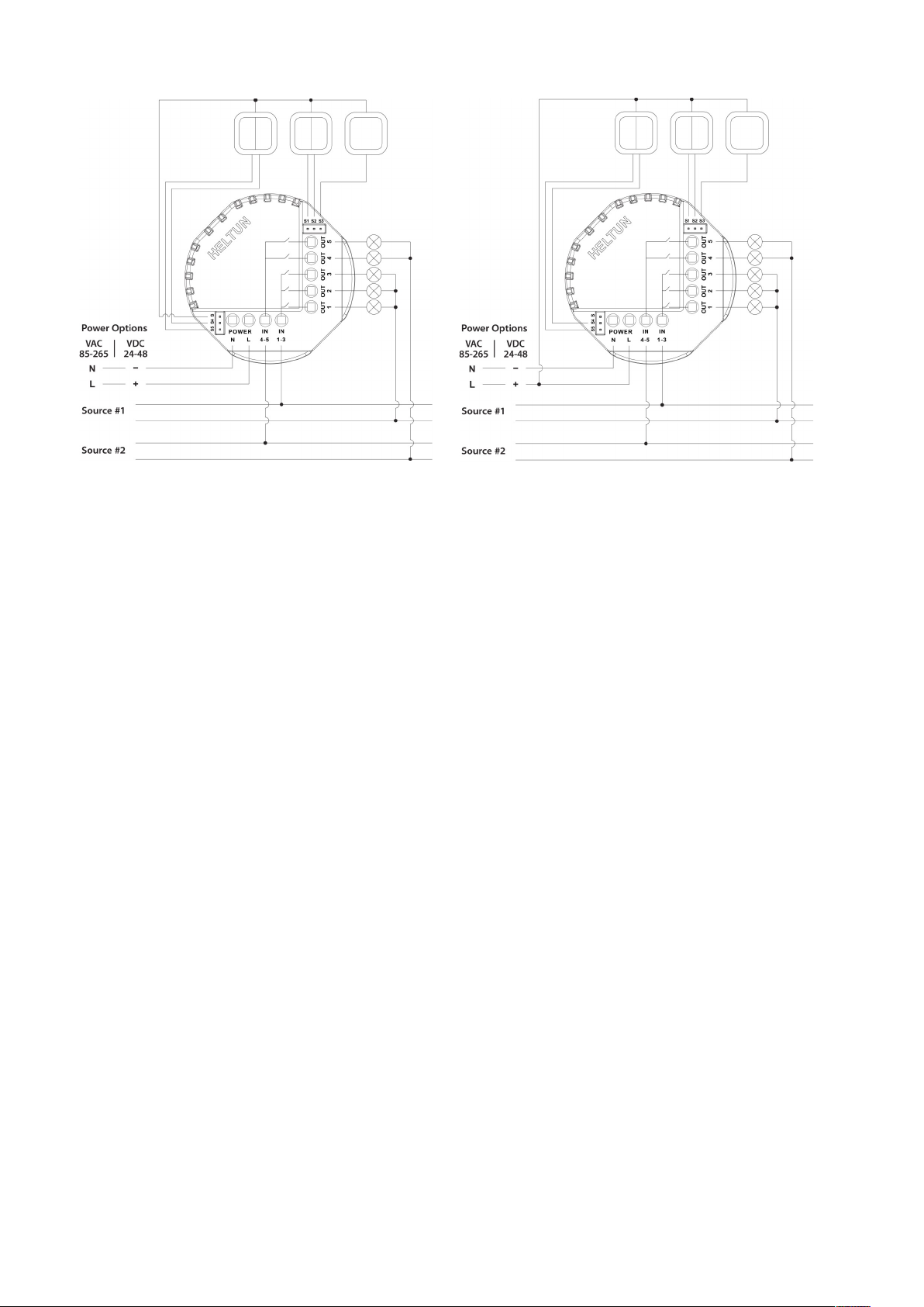
Figure 2: Power, Loads & External Switches Connection Diagram
3. Next, connect terminals S1, S2, S3, S4, S5 to external control keys (switches) following Fig. 2 left diagram or
Fig. 2 right diagram.
Note: In case of using Figure 2 right diagram, it is MANDATORY to connect external switches to the same wire
connected to terminal L on the device.
4. Switch on the main power at the circuit breaker. The HE-RS01 will start up with original default factory settings
and the LED indicator will blink red slowly meaning the device is excluded from a
Z-Wave network.
Disassembly
1. ENSURE POWER IS SWITCHED OFF at the main circuit breaker AND THE LED INDICATOR IS OFF.
2. Disconnect the wires by inserting a small Phillips-head screwdriver into the slot beneath each wire, then
unscrew to release.
5
 Loading...