

Helo WE-50, WE-52, WE-51 User And Installation Manual
Contactor box WE - 50 (2005 – 50) 400-415V 3N~
WE - 51 (2005 – 51) 400-415V 3N~
WE - 52 (2005 – 52) 230-240V 3~
Control panels
- Premium Wifi (1601 – 33)
- Trend (1601 – 31)
Premium Wifi Trend
Contactor box WE - 50
314 SYWE 31-3 A
User and installation manual
REWARD YOURSELF

Contents Page
1.1. Check before taking a sauna bath 3
1.2. Sauna room 3
1.3. Operation of the sauna heater controls 3
1.4. Operation of the sauna heater controls 3
1. Preparing for sauna heater installation 4
2. Installation 4
3. Safety clearances for sauna heaters 1101 and 1105 – XX …….. 5
4. Safety clearances for sauna heaters 1106 – XX (SKLF / Octa) 6
5. Cables and fuses for heaters 1105 – XX (SKLE / Laava) 7
6. Cables and fuses for heaters 1101 – XX (SKLA / Magma) 7
7. Cables and fuses for heaters 1106 – XX (SKLF / Octa) 7
8. Using the contactor cases 8
9. Locating the connecting box for the connection cable in the sauna room 8
10. Door switch 9
11. Remote controlling 9
12. Wiring diagram WE - 50 and 52 10
13. Wiring diagram WE - 51 11
14. Principle diagram 12
15. Connection principle 13
16. Internal connection for sauna heaters SKLE / LAAVA 14
17. Circuit board RJ connectors 15
18. Installation of two SKLA/Magma heaters in a sauna room. 16
19. ROHS 17
Figure and Tables
Figure 1. Installation location of the OLET 31 ……… 5
Figure 2. Alternative installation location of the OLET 31 sensor…… 5
Figure 3. Safety clearances to heater SKLF / Octa 6
Figure 4. Location for the connection box 8
Figure 5. Pin layout of a RJ10 circuit 9
Figure 6. Installing the door switch 9
Figure 7. Wiring diagram for contactor box WE - 50 and 52 10
Figure 8. Wiring diagram for contactor box WE - 51 11
Figure 9. Principle diagram of connection 12
Figure 10. Principle diagram of connections 13
Figure 11. Internal connection for sauna heaters SKLE / Laava 14
Figure 12. Internal connection for sauna heaters SKLF / Octa 14
Figure 13. Internal connection for sauna heaters SKLA / Magma 15
Figure 14. Installation of two heaters in a sauna room. 16
Figure 15. Installation of the sensors of two sauna heaters……… 16
Table 1. Safety clearancest to heater 1105 – xx (SKLE / Laava) 5
Table 2. Safety clearances 1101 – xx (SKLA / Magma) 6
Table 3. Safety clearances to heater 1106 – xx (SKLF / Octa) 7
Table 4. Kables and fuses for heater 1105 – XX (SKLE / Laava) 7
Table 5. Kables and fuses for heater 1101 – XX (SKLA / Magma) 7
Table 6. Kables and fuses for heater 1106 – XX (SKLF / Octa) 7
Table 7. Connecting the door switch to an RJ10 connector. 9
Table 8. Instructions for connecting OLEA 103 RJ 10 circuit board for remote control 9
Table 9. Circuit board RJ connectors 15
Table 10. Safety distances in a two-heater installation. 17
User and installation manual
2
WARNINGS
1.1. Check before taking a sauna bath
1. The sauna room is suitable for taking a sauna bath.
2. The door and the window are closed.
3. The sauna heater is topped with stones that comply with the manufacturer's
recommendations, the heating elements are covered with stones, and the stones
are piled sparsely.
NOTE! Ceramic rocks are not allowed.
The heater's main switch is located at the bottom of the heater, on the right side as
seen from the front.
The main switch is marked with a 0 – 1 sticker.
1.2. Sauna room
The walls and ceiling of a sauna room should be thermally well insulated. All
surfaces that store heat, such as tiled and plastered surfaces must be insulated. It is
recommended to use wooden panel cladding inside the sauna room. If there are
heat storage elements in the sauna room, such as decorative stone, glass etc., note
that these elements may extend the pre-heating period even though the sauna room
is otherwise well insulated (see page 4, section 1. Preparing for sauna heater
installation).
1.3. Operation of the sauna heater controls
This appliance may not be used by children aged less than eight years, by persons
with reduced physical, sensory or mental capabilities, or by persons lacking
experience and knowledge regarding its operation only if such have been given
instructions on the safe use of the device and the risks involved. Children must not
be allowed to play with the appliance or to clean and service it without supervision.
(7.12 EN 60335-1:2012)
1.4. Operation of the sauna heater controls
Refer to the specific control panel operating instructions.
Rearrange the sauna stones at least once a year and replace any weathered
stones. This enhances air circulation between the stones, which extends the useful
life of the thermal resistors.
If you encounter any problems, please contact the manufacturer's warranty service
shop.
For additional information about enjoying a sauna bath, please visit our website at :
www.tylohelo.com
User and installation manual
3
1. Preparing for sauna heater installation
Check the following before installing the sauna heater.
- The ratio of the heater's input (kW) and the sauna room's volume (m3). Volume recommendations are presented
in Tables 1, 2 and 3 on page 5, 6 and 7. The minimum and maximum volumes must not be exceeded.
- The height of the sauna room must be at least 1900 mm or 2200 mm depending on the heater power.
- Uninsulated and masonry stone walls extend the preheating time. Each square metre of plastered ceiling or wall
surface adds 1.2 m3 to the sauna room's volume.
- Check page 7 Table 4, 5 and 6 for a suitable fuse size (A) and the correct diameter of the power supply cable
(mm²) for the sauna heater in question.
- Conform to the specified safe clearance around the sauna heater.
- There should be enough room around the control panel for maintenance purposes. Also a doorway can be
considered as a maintenance area.
2. Installation
Follow the safety clearance specifications on pages 5, 6 and 7 on tables 1, 2 and 3 when installing the sauna
heater.
The sauna heater is a floor-standing model. The base must be solid, because the sauna heater weighs
about 80-130 kg.
The sauna heater is levelled by the adjustable legs.
The sauna heater is fixed on the floor from its legs by the provided metal fasteners (2 pcs). This will keep the safety
clearances intact during use.
Walls or ceilings must not be clad with fibre-reinforced plaster board or other light-weight cladding, because they
may cause a fire hazard.
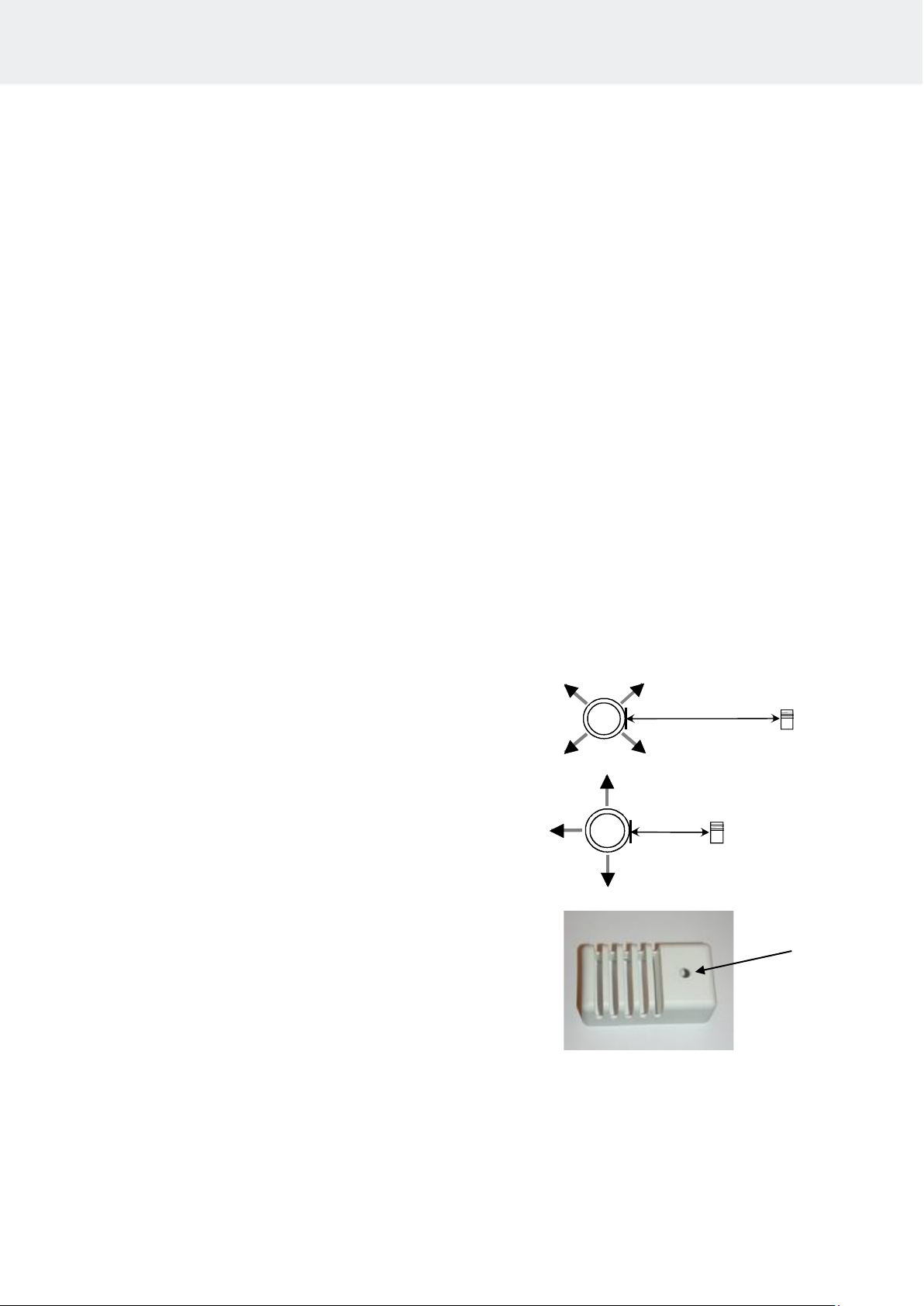
Installing the sensor near a supply air vent
The sauna room air should be exchanged six times in an
hour. The diameter of the supply air pipe should be
between 50 and 100 mm.
A circular air supply vent (360°) must be
installed at least 1000 mm away from the sensor.
An air supply vent with a flow-directing panel
(180°) must be installed at least 500 mm away from
the sensor. Air flow must be directed away from the
sensor.
Ceiling installation of the sensor
In ceiling installation, a 5-mm hole must be drilled to the
sensor case to allow any condensed water to drain.
Do not spray water directly towards the sensor or splash
water at it with a sauna scoop.
Installing the Extra NTC sensor
The additional OLET 31 sensor is connected to the Ext NTC connector on the RJ10 circuit board. For more details,
refer to the switch diagram. The additional sensor is installed on the sauna room wall no more than 500 mm from
the ceiling. Once the additional sensor has been connected to the circuit board, it is automatically activated. This
means that the temperature shown on the control panel is measured by the additional sensor.
The primary sensor installed above the sauna heater only has the limiter circuit that limits the maximum temperature to 110 °C. Even if the temperature is set to 110 °C on the control panel, the maximum temperature that can be
shown on the panel is approximately 90 °C, as the primary sensor above the heater limits the maximum temperature to 110 °C. Depending on individual preferences, the temperature of a sauna room is typically set between 70
and 80 °C.
Ø 5mm
User and installation manual
4
360°
1000 mm
180°
500 mm
Sensor
Sensor

3. Safety clearances for sauna heaters 1101 and 1105 – XX (SKLE / Laava and
SKLA / Magma)
Power
kW
Sauna volum
Minimum distances
Adequate amount
of stones
Approx. kg
Min.
Max.
Minimi
-
height
To the side
wall
To the
front
To the cei-
ling
To the
back
m3 m3
H
A
mm D mm F mm
C
mm
mm
9,0
8
13
1900
80
80
1200
110
60
10,5
9
15
1900
80
80
1200
110
60
12,0
10
18
2100
120
120
1400
120
60
15,0
14
24
2100
120
120
1400
120
60
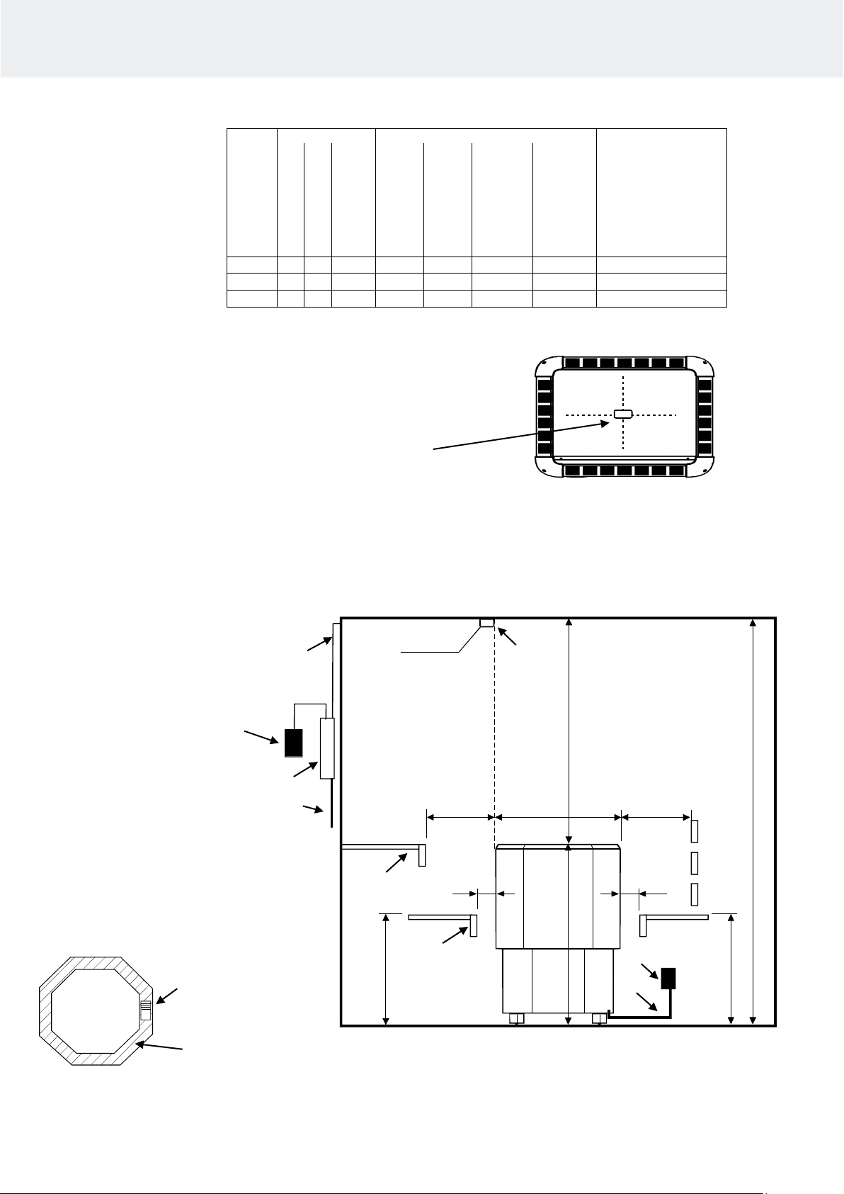
Table 1 Safety clearancest to heater 1105 – xx (SKLE / Laava)
1 3 4 9 H A D
Max
500 mm
Min
100mm
40 mm
2
F
Figure 1. Installation location of the OLET 31 sensor
40 mm from the ceiling in the centre of the heater.
The safety distance between the heater and the wall
behind the heater must be at least the minimum distance listed in tables 1 SKLE / Laava and tables 2 for
the SKLA and Magma heaters.
Figure 2. Alternative installation location of
the OLET 31 sensor on a ceiling in the
centre above the heater.
1105-… SKLE / Laava
1. Contactor box WE - 50
2. Sensor OLET 31
3. Temperature resistant cable for sensor
4. Feed cable to the sauna heater
5. Connection box
6. Connection cable to the sauna heater
7. Lower bench or railing
8. Upper bench or railing
9. Control centre Trend or Premium wifi
Note! Alternative installation location of
the OLET 31 sensor on a ceiling in the
centre above the heater.
User and installation manual
5
6 D H 5 7 8 2 F
C > min
Power
kW
Sauna volum
Minimum distances
Adequate amount
of stones
Approx. kg
Min.
Max.
Minimi-
height
To the side
wall
To the
front
To the cei-
ling
To the
back
m3 m3
H
A
mm D mm F mm
C
mm
mm
18
18
30
2100
140
160
1400
160
100
21
24
36
2100
140
160
1400
160
100
26
30
46
2200
140
160
1500
160
100
Table 2 Safety clearances 1101 – xx (SKLA / Magma)
4. Safety clearances for sauna heaters 1106 – XX (SKLF / Octa)
Figure 3. Safety clearances to heater SKLF / Octa
User and installation manual
6
1. Contactor box WE - 50
2. Sensor OLET 31
3. Temperature resistant cable for sensor
4. Feed cable to the sauna heater
5. Connection box
6. Connection cable to the sauna heater
7. Lower bench or railing
8. Upper bench or railing
9. Control centre Trend or Premium wifi
A min 560 D min
10 10
max
500
max
500
min
H
min
F
760
OLET 31
1
2 3 4
7
8
9
5
6
1106-… Octa
NOTE: The OLET 31
sensor is installed
directly on the ceiling,
in line with the side of
the heater.
Sensor installation area
Heater
1101-… SKLA / Magma
Note! Alternative installation location of
the OLET 31 sensor on a ceiling in the
centre above the heater.
 Loading...