

Helo T2 Installation And User Manual

OH
CONTROL CENTRE RA – 28 (T2)
314 SYRA 67-3 C
OK
Installation and User's Manual Helo T2

Contents
1. General 2
1.1 Check the following before taking a sauna bath 2
1.2 General information on the control panel 2
2. Circuit diagram 3
3. Basic schematic of the terminal connections and the installation 4
4. Installation and use of control panel T2 5
4.1 Control panel T2 6
4.2 Control panel functions 7
5. External switch function 10
6. RoHS 11
1. General
1.1 Check the following before taking a sauna bath
1. The sauna room is in an appropriate condition for taking a sauna bath.
2. The sauna room door and the window are closed.
3. The sauna heater is topped with stones that comply with the manufacturer's recommendations; the stones
cover the heating elements; the stones are piled in the sauna heater leaving copious amounts of space in
between.
4. Temperatures approaching 70°C assure a pleasant, smooth sauna bath experience.
1.2 General information on the control panel
Control centre 1601 – 28 (T2) and contactor case 2005 – 14 (WE – 14) can be used with the following sauna
heaters:
- SKLE - .… 1105 - ….
- SKLA - …. 1112 - ….
The Contactor case should be installed outside the sauna room. The cables should be installed using the
protocols for permanent installation. A split box with a semi-permanent installation into the sauna heater should
be attached inside the sauna room. Caution: not adhering to the minimum distances indicated in the Installation
manual may cause a fire hazard.
To ensure that that it is in an appropriate condition for bathing, always check the sauna room before switching
on the sauna heater.
Installation and User’s Manual Helo T2
2
2. Connection diagram
1.
Syöttö / Nätet / Stromnetz / Power input. / Puissance absorbée / Vermogensingang /
Entrada de alimentación /
2. Kiuas / Bastuugn / Sauna heater / Saunaofen / Calentador de sauna / Chauffe-sauna /
Elektryczny piec /
3.
Ohjauskeskus / Styrpanel / Steuergerät / Control panel. / Panneau de commande /
Bedieningspaneel / Panel de control / / min.LiYY 4x0.25mm
2
4. Termostaatti / Sensor / Fühler / Sensor / Capteur / Sensor / Czujnik /
5. Ovikytkin / Dörrströmbrytare / Door switch / Türschalter / Interrupteur de porte /
Interruptor de puerta /
Входное напряжение / Wejście zasilania.
Пульт управления / Panel sterujący
Датчи к
ЭЛЕКТРОКАМЕНКА
354 SYWE 19 D
1a.
1b.
2a.
2b.
F2
10 A
N L1 L2 L3 N U1 V1 W1
N L1 L2 L3
N U2 V2 W 2
N
L
R9 R7 R5
Securityrelay
R8 R6 R3
OLEA 97
Lamp
SR3
SR4
R1
R2
SR1
SR2
17
18
3.
4.
N 55 N
400V - 415V 3N~
F1
1 AT
Si
Va
Pu
Ke
Ru
Va
Vi
Ke
5.
N L1 L2 L3
1a.
230V 3~
Max 21 kW
A
B
1
1
1
2
5
1
5
2
Mu
Ru
N L1 L2 L3
1b.
A
B
1
1
1
2
Дверно й вы ключатель / Rozłącznik na drzwiach
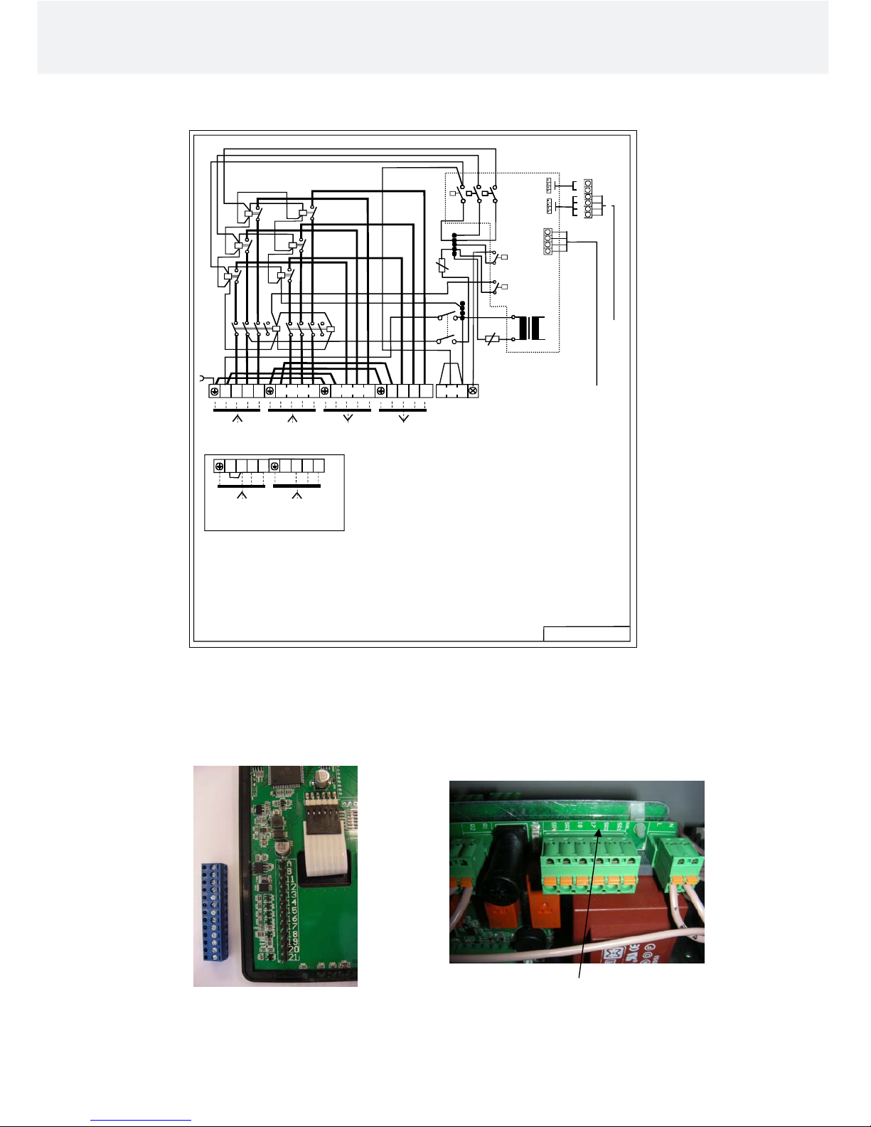
2.1 Connecting the control cables and the circuit board
NOTE: The cable connecting the Contactor case WE-14 to the Control centre must be screened, e.g. LiYY 4 x
0.25mm². Maximum length of the cable is 50m.
Connecting terminal markers A, B, 11 Sensor markers SR1 and SR2 as well as
and 12 of the Control panel T2 17 and 18 of the circuit board
Installation and User’s Manual Helo T2
3
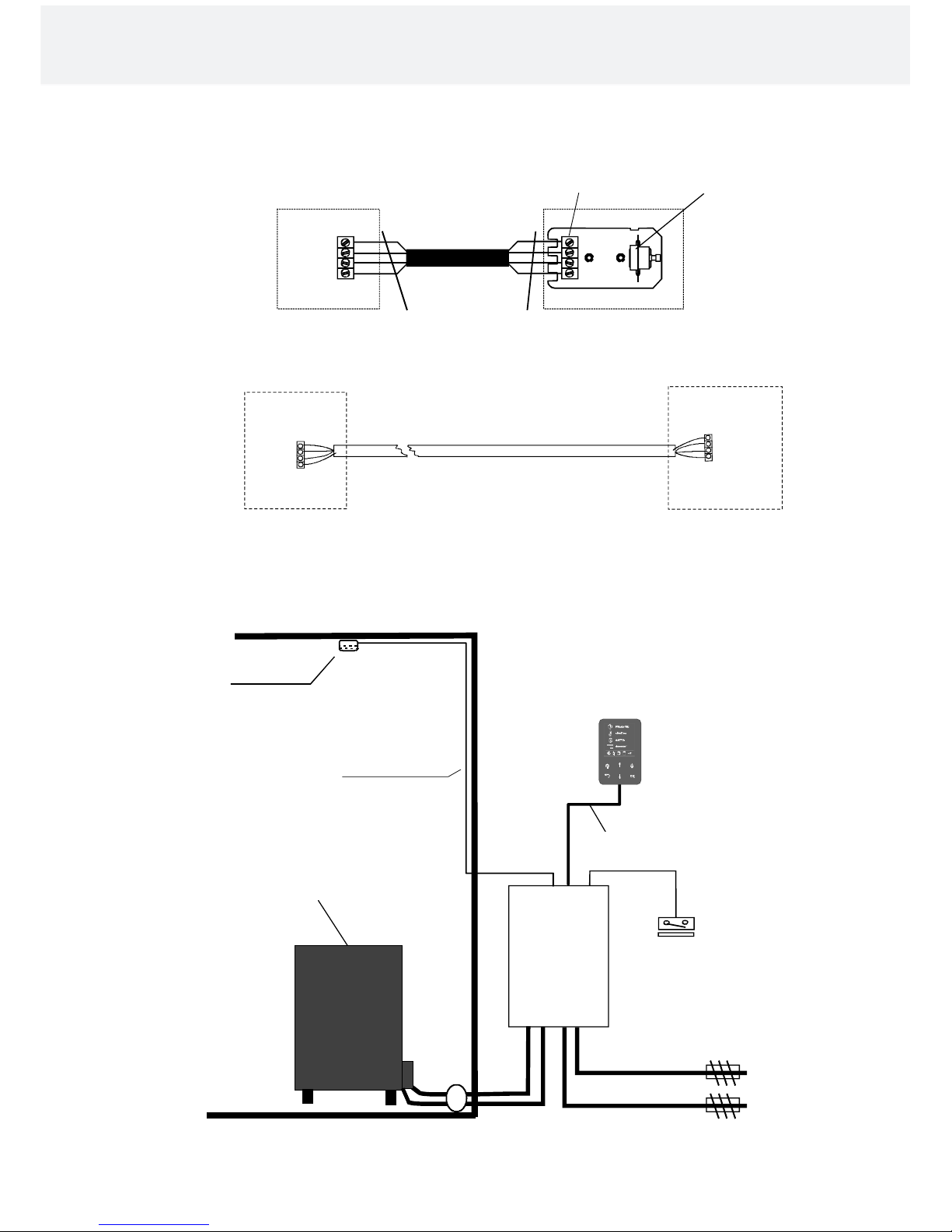
3. Basic schematic of the terminal connections and the installation
SR 1
SR 2
17
18
1
2
3
4
A
B
11
12
A
B
11
12
Installation and User’s Manual Helo T2
4
SR 1. Blue
SR 2. White
17. Red
18. Yellow
Limiter
Connector strip
Contactor box
Sensor cable
Control panel
1601-28 (T2)
Sensor
OLET 28
Sauna heater
Silicone 4 x 0.25
Control panel
1601-28 (T2)
LiYY 4 x 0.25
Power supply
400V – 415 V 3N~
230 V 3~
A. Ruskea Brun Brown Braun
B. Valk Vit White Weiss
11. Vihreä Grön Green Grün
12. Kelt Gul Yellow Gelb
1. Blue
2. White
3. Red
4. Yellow
Contactor box
Door switch
Contactor box
WE 14
 Loading...