

Helo Saunatonttu 8, Saunatonttu 4, Saunatonttu 6, Saunatonttu 3 Instructions For Installation And Use Manual
GENUINE SAUNA & STEAM
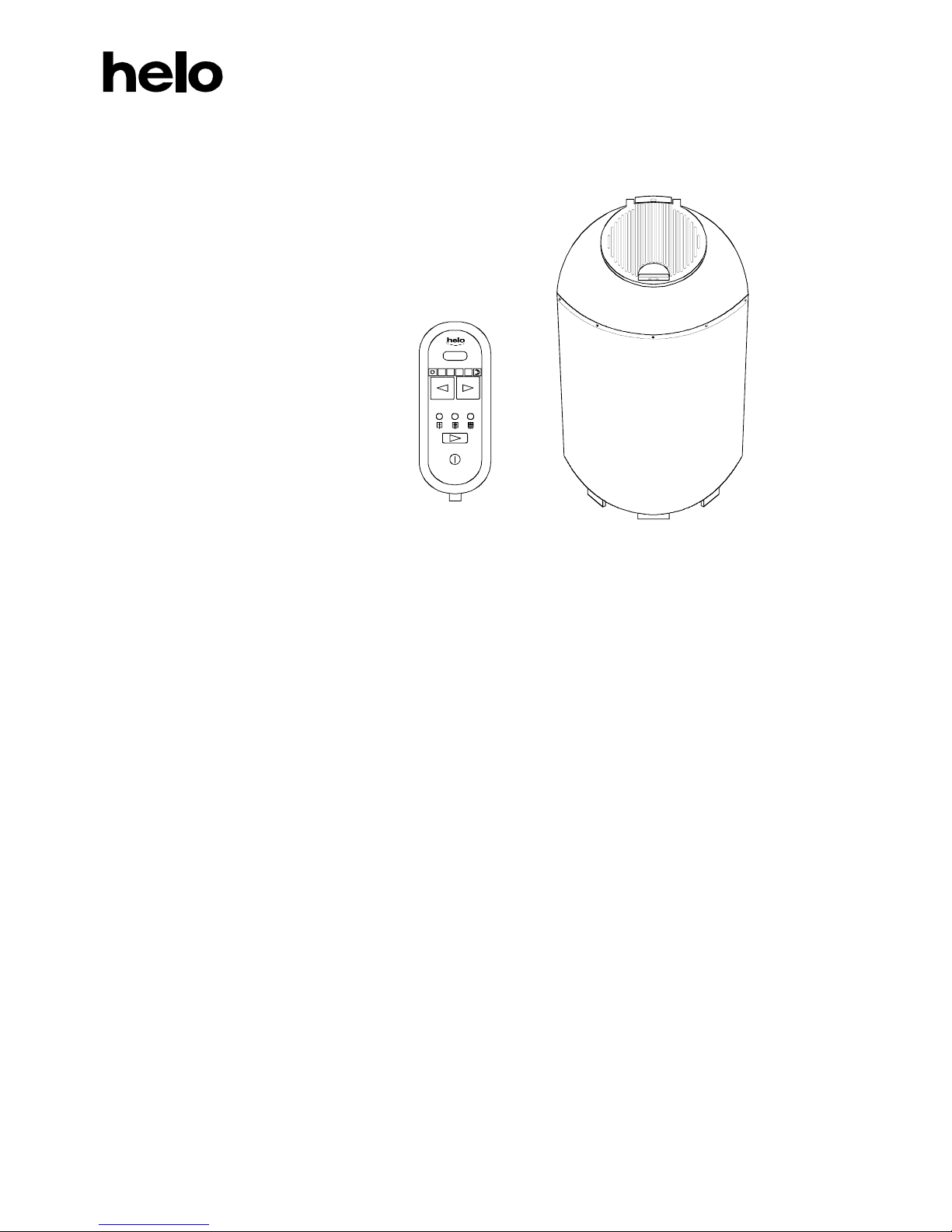
HEAT STORING ELECTRIC SAUNA HEATER
Saunatonttu 8, 6, 4 and 3
INSTRUCTIONS FOR
INSTALLATION AND USE
400V~ 3N
Model 2000780 8.0 kW
Model 2000764 6.4 kW
Model 2000748 4.8 kW
3.4 kW
230V~ 1N
Model 2000734 3.4 kW
2.0 kW
HEAT STORING SAUNA HEATERS ARE TECHNICALLY ADVANCED WITH SEVERAL OPTIONS FOR
USE. THEREFORE, PLEASE READ THIS MANUAL CAREFULLY.
THE PERSON INSTALLING THE SAUNA HEATER SHOULD LEAVE THESE INSTRUCTIONS TO THE
PREMISES FOR THE FUTURE USER.
CONTENTS
General information before use 2
Preparing for sauna heater installation 2
Sauna room 2
Sauna room ventilation 3
Sauna heater installation 3
Mains connection 4
Electric heating toggle 4
Sauna heater thermostat 4
Temperature limiter 4
Sauna heater stones 4
Connection of control current 5
Heating the sauna heater to standby mode 5
Taking a sauna bath 6
Table for selecting a sauna heater 7
Table for electrical connections and fuses 7
Images 8
Circuit diagrams 9
Saunatonttu 8 10
Using the control panel 11
7013977 314 SKLH 16D
ON OFF
0153060

2
You are now using an electric sauna heater that is manufactured in accordance with the best knowhow and
experience in the world.
Helo Oy group has its roots in 1919. We've been manufacturing electric sauna heaters for more than 50 years.
Over the decades, several hundred work years have been used for developing sauna heaters. This experience and
knowhow is known around the world: several testing institutes in the world's sauna countries have given their approval
to Helo Oy's electric sauna heaters.
GENERAL INFORMATION
1. Please read the instructions for use carefully.
2. Wash and pile the stones.
3. Before turning the sauna heater on, make sure the sauna room is suitable for taking a sauna bath.
4. Preheat the sauna heater in full power for at least 3 hours. The heating removes any storage grease. If
an odour still persists, continue heating until it stops.
Remember adequate airing between heatings. The door or window must be kept closed during
heating.
5. Persons with reduced physical and mental capacity, sensory handicap, or little experience and
knowledge about how the device is operated (e.g. children), should only operate the device while
supervised or according to instructions given by the persons in charge of their safety. Make sure that
children are not playing with the sauna heater.
6. If any problems occur, please contact the nearest authorised service.
Contact information is available at www.helo.fi
.
PREPARING FOR SAUNA HEATER INSTALLATION
When you get these instructions, a suitable sauna heater is usually selected already. However, the following points
should be considered and checked before installing and using the sauna heater.
1. The ratio of the heater's input (kW) to the sauna room's volume (m³). The minimum and maximum
volumes stated must not be exceeded.
2. The sauna room must be at least 1900 mm high.
3. The heat storing surfaces in the sauna room ceiling and walls (brick, tiles, plaster, timber, or such) must
be insulated with e.g. mineral wool.
4. The fuse size and the power supply cable diameter must be adequate for the sauna heater's power rating.
5. Adequate space must be reserved for the sauna heater. See Installation on page 8.
6. The control panel must be placed so that is easily accessible. See instructions for installation on page 8.
SAUNA ROOM
The walls and especially the ceiling of a sauna room should be thermally well insulated. All heat storing surfaces (brick,
plaster and such) must be insulated, using also aluminium paper (bright side inwards).
Timber surfaces must also be insulated.
Fire authority regulations must be considered when covering chimney flues. Always check adequate insulation in
different surfaces and structures with a professional (an architect or a structural engineer).
Uninsulated heat storing surfaces will slow down the rising of temperature. Apart from that, they may first release steam
into the sauna room, because with the Saunatonttu sauna heater, the sauna room temperature is raised rapidly by
throwing water on the sauna heater.
1 m² of uninsulated stone surface in the ceiling and upper walls increases the measured volume of the sauna room by
1.5–2 m³, and a similar surface of timber wall a half of that. However, the specified minimum and maximum volume of
the sauna room must be adhered to. Steam room boarding (wood panel) must extend all the way to the ceiling, so that
the hot air near the ceiling does not flow into the air passage behind the boarding and heat up the insulation. Moreover,
hot air carries a lot of water, which will condensate into liquid water when the air cools down behind the panel.
Appropriate sauna room height is 2–2.1m. When the sauna room is not too high, the upper seat can be installed at 1050–
1100mm from the ceiling, and the bather can sit where the heat is.
The minimum height of a sauna room according to the regulations is 1900mm.

3
SAUNA ROOM VENTILATION
Appropriately planned ventilation creates pleasing conditions for bathing and saves energy. Proper ventilation and
smooth steam ensure enjoyable conditions for bathing. Always use a professional planner for a ventilation plan.
The placement of air valves is critical for successful ventilation. Fresh air intake valve should be placed in zone A and at
least 500mm above the sauna heater. Exhaust valve is placed near the floor. Alternatively, the exhaust air can be led
under the sauna room door to the washroom exhaust valve. This is a very good solution in family saunas. See the image
below.
If there is no exhaust flue to the roof and no forced ventilation, the exhaust valve must be placed at least 1m higher than
the intake valve to ensure air circulation.
SAUNA ROOM VENTILATION
Recommended sauna room ventilation system, when an exhaust air extractor fan is available.
5
5
4
4
2
1
1
C
C
7
CC
min
500 mm
6
1000mm
1000mm
A
A
1
3
B
3
B
1. Sauna room 3. Electric sauna heater 5. Exhaust flue or channel
2. Washroom 4. Exhaust valve 6. Door to the sauna room
7. A ventilation valve can be installed here; keep it closed while the sauna is heated and during bathing.
A fresh air intake vent can be positioned in the zone A. Make sure the incoming fresh air will not interfere with (i.e.
cool down) the sauna heater's thermostat near the ceiling
The zone B serves as the incoming air zone, if the sauna room isn't fitted with forced ventilation. In this case, the
exhaust valve should be installed at least 1m higher than the inlet valve.
A FRESH AIR INTAKE VALVE MUST NOT BE PLACED IN ZONE C, IF THE THERMOSTAT IS NEAR THE
CEILING (NOT APPLICABLE FOR HEATERS WITH BUILT-IN THERMOSTAT).
SAUNA HEATER INSTALLATION
The sauna heater is a free-standing model. The base must be solid, because the sauna heater weighs about 150 kg with
the stones. The adjustable legs are used for balancing the heater.
The heater must not be installed in a rectangular bay.
The minimum safety clearances are specified in a plate attached to the lower front of the heater, see the image on page
8. The specified minimum safety clearances must be adhered to regardless of the surface materials in the sauna room.
This also applies to incombustible surface materials, as provided in the electrical safety regulations.
The ceiling must not be clad with light-weight cladding (fire classified or other), because they may cause a fire hazard.
Two wooden fasteners are provided with “Saunatonttu” sauna heater to prevent it from moving. See the image on page
8.
If the sauna heater is not installed in a corner, it can be fixed on the floor by the adjustable legs. The heater may also be
locked in place by wooden stoppers. The stoppers must not be installed higher than 400mm from the floor.
A single sauna heater is allowed per a sauna room.

4
MAINS CONNECTION
Electrical installation must be carried out by a qualified electrician. The electrician must have qualifications for
electrical installation or be supervised by a person with such qualifications.
Sauna heater is connected with a semi-permanent connection. Use H07RN-F (VSN) (60245 IEC 66) cable or a
corresponding type. Do not use PVC insulated cable as a connection cable for the sauna heater. All sauna heater's output
cables must be of the above or corresponding type.
See the circuit diagrams at the end of the instructions.
The maximum installation height for the connection cable's connecting box is 0.5m from the floor. If the connecting box
is located further than 0.5m from the heater, the maximum height is 1m from the floor. However, in this case (further
than 0.5m), the connection cable must be of heat-resistant type (T 170°).
Adhere to the effective electrical safety regulations when installing the sauna heater.
The heater's functions must not be tested without stones.
ELECTRIC HEATING TOGGLE
Sauna heater has a connection (n:o 55) for controlling the electric heating toggle. The connection and the heating
elements are simultaneously live. This means that the sauna heater thermostat also controls the heating toggle. In other
words, heating turns on once the sauna thermostat cuts power off the sauna heater.
NOTE: There is no toggle between the simmering levels and heating.
SAUNA HEATER THERMOSTAT
The sauna heater thermostat limits the temperature of the stones to max 350°C. The thermostat is inside the connecting
box behind the sauna heater.
When installing, make sure the thermostat is turned right to the max position (as if tightening a screw).
TEMPERATURE LIMITER
The sauna heater has a temperature limiter as a safety device to stop the heater from overheating in case of fault. The
limiter is reset manually. To reset, press the round rubber cover at the back of the sauna heater, top right. The limiter
cannot be reset until the heater has cooled down.
The temperature limiter cuts off the power very rarely. If the limiter cuts of the power, call in a service person to correct
the fault.
SAUNA HEATER STONES
The electric sauna heater stones should have the following qualities:
1. Heat resistant and resistant to great temperature fluctuations caused by turning water into steam.
2. Odour and dust free.
3. Suitable (not too good) thermal conductivity to allow water to "stick" to the stones and not flow past
them. Water stays better on uneven cleavage planes.
(An example of a too good thermal conductivity is a hot plate, where water doesn't stay but forms small
beads of water on the surface.)
4. Large enough to allow good ventilation inside the heater, which effectively and evenly cools down the
heating elements.
When piling the stones, remove the black ceramic rings from the opening in the heater..
 Loading...