

Helo HSX M 34, HSX M 60, HSX M 47, HSX M 77, HSX M 95 Operating And Installation Instructions
...
GENUINE SAUNA & STEAM
New HELO- HSX M steam generator for home and
professional use.
- Operating instructions
- Installation instructions
Operating and installation instructions for models:
HELO HSX M 34, 47, 60, 77, 95, 120, 140.
7014121 314 SHS 56 E
2
Technical specifications:
• Voltage: 400V – 415V 3N~ 50Hz (230V – 240V 1N~ 3.4 – 7.7 kW).
• Power alternatives: 3.4kW-14kW.
• Enclosure rating: IP 20.
• Installation mounting: Floor/Wall.
• Water tank material: Aisi 316, acid-resistant steel.
• 2-phase control for thermal resistance. (Not in the special Belgian version)
• Steamer dimensions: 520 x 380 x160 mm
Easy to use:
• Automatic discharge and flush programme.
• Automatic fill and water level control.
• Floor or wall mounting.
• Digital control panel.
- Temperature control
- Time setting
- Light control
• Control panel can be installed inside the steamroom.
• Magnetic valve equipped with a large discharge port, allowing larger contaminants and lime
deposits to be flushed from the tank after each use. (Accessory)
Easy to maintain:
• Replaceable resistors (3 pcs), 1 of which is equipped with a thermal fuse.
• Lime remover (citric acid) fill port is conveniently located on top of the steam generator.
• Components can be easily replaced:
- Circuit board
- Thermal resistors
- Surface level sensor
3
OPERATION AND INSTALLATION:
The HSX steam generator is only intended for use in the heating of steambaths. Use of the steam
generator in any space other than intended can result in structural damage.
The manufacturer is not liable for any damages caused by installation in a space not inlended for
steambath use, or misure of the generator.
Before connecting the steam generator to the mains power, connect all water and steam lines. All
lines must be connected with the greatest care. Ensure that all joints are properly sealed. Although
thread seal tape can be used to properly seal threaded joints, soldering the joints is recommended.
The steam generator should be placed away from water and moisture (dry space). The space should
be well-ventilated, as the steam generator also generates heat. The minimum recommended safety
clearance on each side and above the generator is 30 cm. When placing the steam generator, also
take into consideration the space required for its maintenance.
Ensure that there is a drain in close proximity to the steam generator for discharging the tank.
The steam generator can be mounted on the floor (free standing) or on the wall using mounting
brackets. When using wall brackets, use a fastening method and mounting screws appropriate to the
wall material in question. When filled with water, the steam generator weighs approx. 17 kg.
If the automatic discharge valve is being used, a wall-mounting is recommended to ensure the
proper discharge pressure in the discharge pipe leading into the drain.
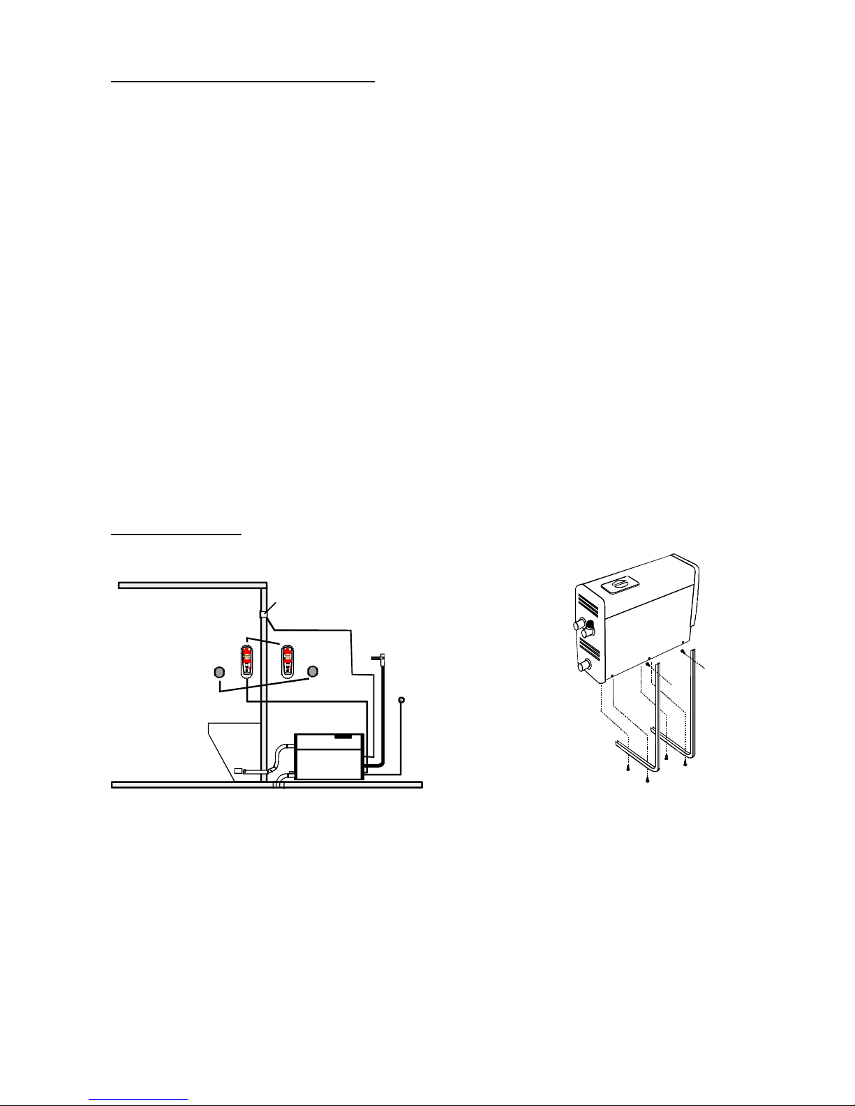
HSX M installation
The control panel can be mounted either inside or outside the steamroom. If the control panel is
mounted outside the steamroom, a separate thermostat connected to the circuit board must always
be used.
Wate r connecti on
400V 3N~
Discharge
Temperature sensor
Contr ol panel
Steam nozzle
OK
ON OFF
OK
ON OFF
Button
Location of control panel and button Steam generator wall mounting

4
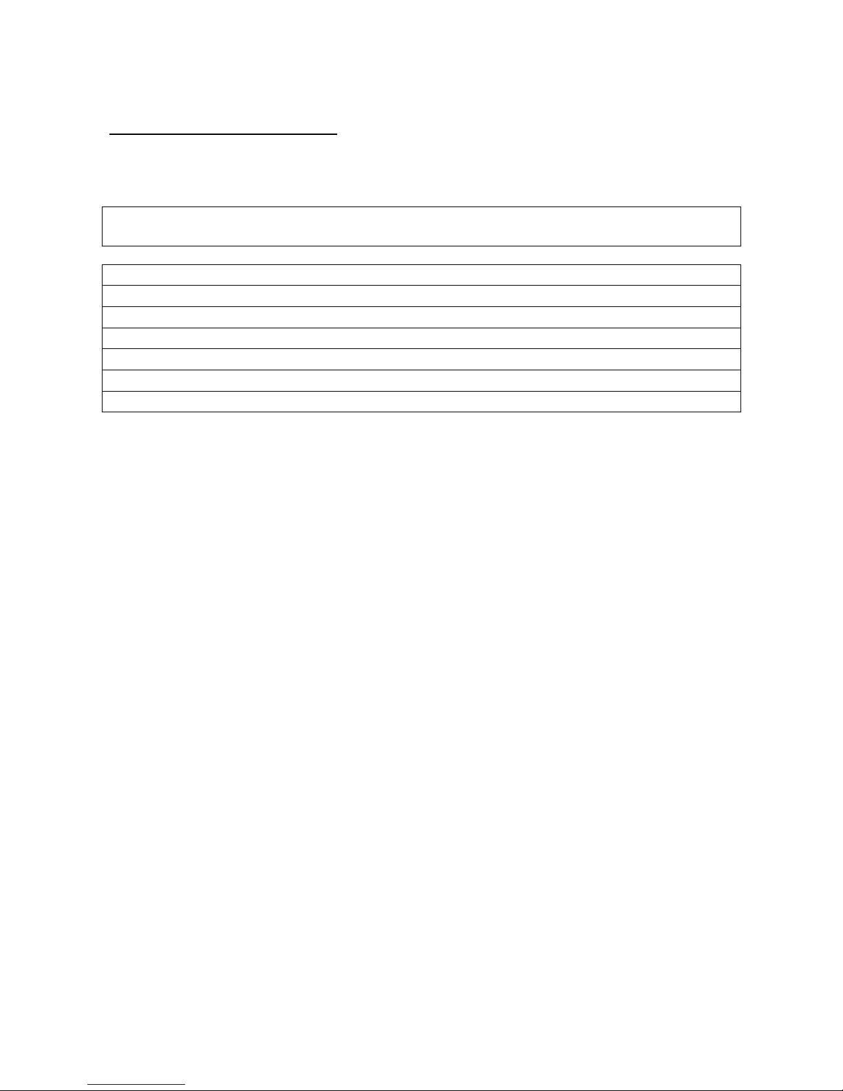
EQUIPMENT CONNECTIONS
Water and steam line connection
Connect the ¾” flexible water line hose (included in package) from the water connector on the
steam generator installation panel (see figure) to the household cold water line. The water pressure
should be a minimum of 0.2 bar and maximum of 10 bar. The water feed pipe should be fitted with
a manual shutoff valve, which can be used to cut off the flow of water to the generator if it will be
out of use for an extended period of time.
Observe local regulations when installing the steam generator.
The steam line connector should be at least 18x16 mm (generator output: 3.4 kW-9.5 kW) and
22x20 mm (generator output: 12.0 kW- 14.0 kW) copper piping or a similarly sized heat-resistant
silicone hose. The steam line diameter should be consistent for its entire length.
The steam line should go up or down from the steam generator into the steamroom. NO drainage
traps/water pockets may be installed on the line - any water condensation forming in the steam line
must be able to run freely into the steamroom or back into the steam generator. If an odorising
pump has been connected to the steam generator, the line discharge must always run away from the
steam generator, to ensure that the chemicals do not enter the tank.
The maximum recommended steam line length is 5 m.
Additional steam line insulation is always recommneded, both for safety reasons and to prevent
water condensation in the line.
WARNING! Hot steam can cause severe burns.
The manual drain valve supplied with the steam generator is used to empty the steam generator
tank. An electrically-operated magnet valve is available as an accessory.
The steam generator tank should be discharged after each use. This will extend the service life
of the generator and reduce lime deposits.
16
38
52
Water fill
Main switch
Control panel cable
Electrical feed
Overpressure
valve
Steam outlet
Automatic
magnetic
valve
connector
Water discharge valve
(manual or electrically-operated)
5
ELECTRICAL CONNECTIONS:
The steam generator is connected (semi-fixed connection) to the mains power, in accordance with
local installation regulations.
Steamer Power 400V/415V 3N 230V/240V 1N 230V3~ Room size
KW Amp Amp Amp m³ *)
HSX 34 3.4 5/5 15/14 8/8 1.5-2.5
HSX 47 4.7 7/6,5 20/19 12/11 2.5-5
HSX 60 6.0 9/8 26/25 15/14 5-7
HSX 77 7.7 12/11 33/32 19/18 7-10
HSX 95 9.5 15/13 24/23 10-12
HSX 120 12.0 19/17 30/29 12-15
HSX 140 14.0 23/21 35/34 15-18
Electrical connections are only to be installed by a licensed electrician.
*) Walls made of heavy materials, such as concrete, brick or stone require a higher output to
generate sufficient heat. Ventilation must also be given extra power.
The required power output can be estimated using the fomula below.
Volume (m3) x K1 x K2 = Required output (kW)
Ventilation K1 = 0.75
No ventilation K1 = 0.52
Acrylic walls K2 = 1.00
Light construction wall: drywall + tile K2 = 1.25
Heavy construction wall: stone, concrete + tile K2 = 1.50
Steam generator 2-phase control: (Not in the special Belgian version)
The steam generator thermal resistors are 2-phase controlled.
Example: The temperature is set for +43 °C. When the temperature reaches +43 °C two resistors
are switched off with a contactor and one remains on to maintain the temperature with a relay on the
circuit board. If the temperature drops 1 °C, all resistors will be switched back on. If the
temperature rises 1 °C, all three resistors will be shut off. This will ensure an even steam output for
the duration of operation.
 Loading...