

Helo HNS-S, HNS-S PRO Instructions For Use And Installation
STEAM GENERATOR
HNS – S (1317 - … - 17) 3,4 kW – 7,7 kW
HNS – S Pro (1317 - … - 17) 9,5 kW – 16 kW
CONTROL CENTRE
Trend (RA – 31)
Premium Wifi (RA – 33)
314 SHS 108-3 A
Instructions for Use and Installation
REWARD YOURSELF

Contents
Specifications 2
Easy maintenance 3
Accessories 3
General 3
Warnings 3
Installation principle 4
Overheating protector 5
Main switch 5
Ventilation 5
Automatic flushing 5
Automatic interim rinsing during use 5
Descaling 6
Cleaning the steam room 6
Steam generator couplings 7
Water and steam pipe connections 8
Electrical connections 9
Remote control 9
Circuit board RJ connectors 9
Switch diagram 10
Heating elements 11
Steam generator resistors 11
Selecting the steam generator output for the steam room 11
Troubleshooting 12
ROHS 14
Specifications
Operating voltage 230V – 240V 1N~ / 2~
230V 3~
400V – 415V 3N~
Output options 3.4 / 4.7 / 6.0 / 7.7 / 9.5 / 12.0 / 14.0 kW
Steam generator dimensions 520 x 380 x 160 mm
Parallel coupling Max 5 steam generators.
Enclosure class IP 20
Installation Floor / wall
Water tank material Aisi 304, stainless steel
Water tank pipes Aisi 304, stainless acid-proof steel
Weight when empty about 12 kg
Automatic flushing after one hour
of inactivity
Interim rinsing during use
Electric water level adjustment
Electric overfill protector
Limescale-repelling self-cleaning electrodes
Overheating protector
Safety relief valve
Digital control panel RA-31 (Trend) or RA-33 (Premium Wifi)
2
Instructions for Use and Installation HNS – S

Easy maintenance
Replaceable heating elements (3 pcs)
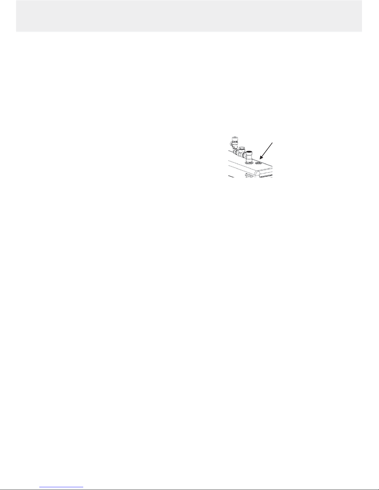
The steam generator has an overheating protector equipped with a reset button
The fill cap for limescale remover (citric acid) has been placed on a steam pipe of the steam generator cover (see
image on page 6).
Components (circuit board, heating elements, surface sensor) are easy to replace.
Accessories
- Essence pump, (Essence pump kit 0038130)
- Essence pump canister 20 l (0038132)
- Automatic flush and rinse cycle. Automatic drain valve 4310130, (included in the Pro models)
- Steam nozzles (3.4 – 6.0 kW 1 piece, 7.7 – 9.5 kW 2 pcs, 12 – 16 kW 3 pcs) (7819604)
General
The HNS-S steam generators are only intended for use in heating spa facilities. Using steam generators in areas
other than steam rooms can damage the building's structure.
The manufacturer is not responsible for damages caused if the unit has been used incorrectly or in a manner for
which the unit was not designed.
Water and steam pipe connections must be made prior to connecting the unit into the mains.
Due care and attention must be taken when making the connections. Proper sealing must be ensured for all
extensions. A good extension must at least have taped-over twist connections, but it is recommended that
connections are soldered.
NOTE: Controlling the lights in the steam room with the circuit board is is only possible with resistive loads
(incandescent light bulbs). The circuit board relay cannot withstand capacitive loads (switched-mode power supply
units). If the lighting fixtures in the sauna have transformers, for example LED or halogen lamps, the steam generator
circuit board's relay control must be fitted with a separate relay or contactor for controlling the lights.
Operation of the steam generator controls
Refer to the specific control panel operating manual for the instructions.
Warnings
- This appliance is not intended for use by persons (including children over the age of 8) with reduced physical,
sensory or mental capabilities, or lack of experience and knowledge, unless they have been instructed about
the safe use of the appliance and the risks involved. Children must not be allowed to play with the appliance or
to clean and service it without supervision. (7.12 EN 60335-1:2012)
- The steam generator produces hot water vapour (100 °C) while in use.
- Disconnect the appliance from the electrical supply before servicing and cleaning it.
- Water connection pressure 0.2–1 MPa (2–10 bar)
Warning: Hot water vapour
3
Instructions for Use and Installation HNS – S
Testing the water before using the steam generator.
The water test kit supplied with the steam generator includes test slips which are used to determine water hardness
as follows:
Dip the test slip in water for about 1 second, take it out and shake off the excess water. After a minute, compare the
colour code appearing on the test slip with the code key in the packet.
Test result: < 3° dH, Very soft water.
> 4° dH, Soft water. Installing the descaling device is recommended
> 7° dH, Medium-hard water. Install descaling device. Retest the water hardness.
> 14°dH, Hard water. Install descaling device. Retest the water hardness.
> 21°dH, Very hard water. Install descaling device. Retest the water hardness.
See page 6 for steam generator's operation time in hours before descaling is required.
The steam generator must be placed away from water and moisture (dry room). The room must be airy as the unit
also produces heat. The temperature of the space where the steam generator is located must not exceed 35 °C. We
recommend leaving at least 300 mm of free space to the sides and above the steam generation unit. Adequate space
for maintenance should also be planned for when placing the unit. There should be a drain nearby for draining the
tank.
The steam generator can be installed as a freestanding unit or installed on the wall using wall fittings. When using
wall fittings, ensure you use appropriate fittings and screws for the type of construction material of your walls. The
steam generator weighs about 18 kg when filled with water.
When the automatic drain valve is used, it is recommended you use wall installation to ensure a suitable angle for
draining water.
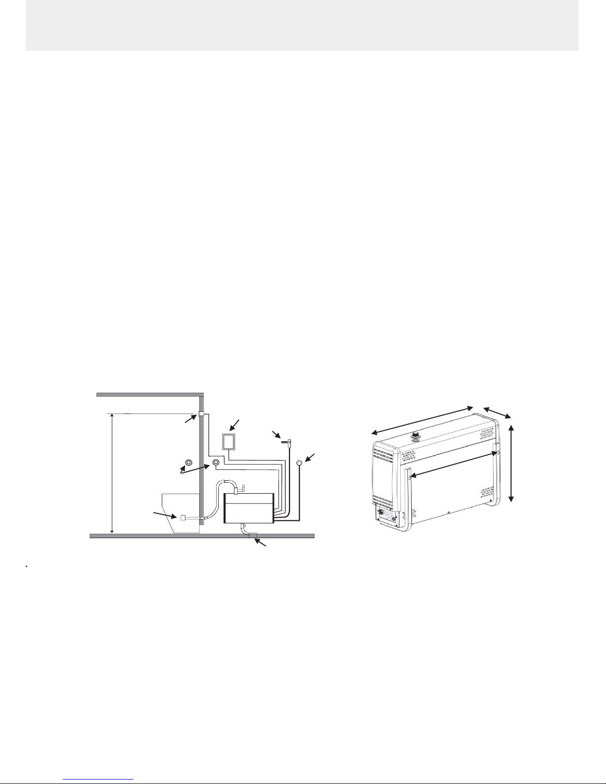
Principle diagram for installation
Installing the control panel Steam generator wall mounting
The control panel of the HNS – S unit is installed outside the steam room.
The cable of the control panel can be extended with a similar cable.
Steam nozzle / nozzles are fitted approximately 200–400 mm from the floor underneath a bench or a seat, or onto
the wall so that the hot steam cannot burn anyone's feet. The steam nozzles are aimed towards the floor. When the
nozzles are installed, you must ensure that you place them somewhere where nobody can accidentally touch them.
The steam temperature is +100 °C and it can cause injuries on contact.
If children or people with impaired reflexes use the steam room, the steam nozzle must be fitted with a protector that
prevents people from getting into the hot steam shower.
4
Instructions for Use and Installation HNS – S
Steam room
On/Off
Push button
Sensor
OLET 22
Control panel
Water connection
Electrical connection
Flushing
Steam nozzle
1700mm
636 mm
380 mm
523 mm
164 mm
The thermostat should be fitted about 1700 mm above the floor, ideally on the wall opposite the door. We
recommend sealing the thermostat installation hole with appropriate sealing material, so that moisture cannot enter
the structures.
The steam room thermometer must installed at the height that gives the same reading as that shown on the control
panel.
The On/Off push button can be used for starting and stopping of the steam generator remotely. The push button
can be placed inside or outside the steam room. For more information about the control panel and reception
couplings, please refer to the user manual and the switch diagram.
Overheating protector
The steam generator is equipped with an overheating protector. If the protector has tripped, find the root cause with
the troubleshooting guide in the instruction manual. The overheating protector is reset by pushing a button.
NOTE: The overheating protector is located under the upper lid of the steam generator. Only a qualified electrician is
allowed to do this.
Main switch
There is a main switch at the bottom of the end of the steam generator, which should only be used when the steam
room will not be used for a long period of time.
The steam generator's automatic flushing and rinsing function will stop if the power is switched off.
(Automatic drain valve)
Ventilation
There is usually no need to ensure ventilation of steam saunas that are used for less than two hours. Steam rooms
that are used for more than two hours at a time, on the other hand, do need ventilation for functional and hygienic
reasons. The recommended rate of ventilation is is 10–20 m³ per person per hour.
If there is an empty space above the ceiling of the steam room, it must not be completely sealed off. Make at least
one ventilation hole (100 mm x 100 mm) leading to the empty space, on the same wall as the door.
The supply air valve may be a hole in the bottom part of the wall with the door or a gap under the door.
The exhaust valve is place in the ceiling or on a wall near the ceiling as far from the supply air valve as possible,
however not above the door or the seats. The exhaust valve is connected to an air conditioning channel going
outside
Forced ventilation. If natural ventilation is not adequate (e.g. negative pressure in the room where the fresh air is
taken from), the steam room must be equipped with forced ventilation. Its output must be equivalent to 10–20 m³ of
ventilation per person per hour.
Automatic flushing
The automatic flushing valve (Automatic drain valve, optional) significantly reduces the accumulation of limescale and
impurities in the water tank. For the flushing and rinsing automation to work, do not switch the power off at the switch
that may be fitted between the switchboard and steam generator or the main switch until at least 80 minutes has
elapsed since the control panel's timer switched the power off. The automatic flushing and rinsing function works as
follows:
After the steam generator stops, flushing starts after approximately 60 minutes. The flushing takes approximately 5
minute,s after which the steam generator tank fills again with cold water and flushes for 5 minutes. This is repeated
once. After this, the steam generator will shut down to stand-by mode until the next programme is initiated. If the
steam generator has stopped and left water in the tank for example because of a power cut. Once the power returns,
the automatic flushing and rinsing of the steam generator starts in the above mentioned manner.
WARNING! The water is hot!
Automatic interim rinsing during use
The automatic interim flushing function flushes the water tank automatically after a certain time. It requires an
Automatic drain valve for an electronic drain valve. The production of steam stops after 10–20 mins depending on the
power.
The RA 33 control panels allow the user to set interim flushings every one to eight hours. For more information about
how to do this, please refer to the control panel user manual.
5
Instructions for Use and Installation HNS – S
 Loading...