

Helo HNS–M2 User And Installation Manual
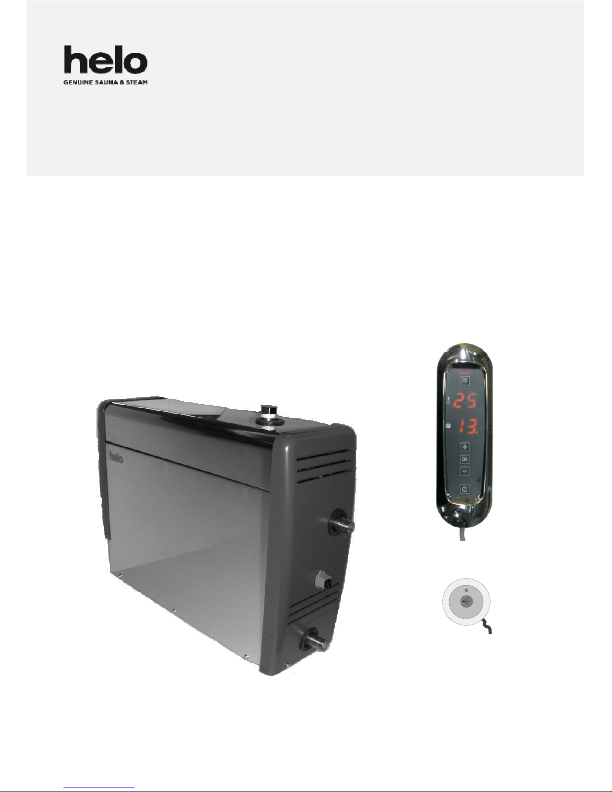
STEAM GENERATOR -- CONTROL PANEL
HNS – M2 -- Midi 2 / On Off push button
For home and professional use
314 SHS 99-3 A
User and installation manual HNS–M2

Contents
Specifications 3
Controls and accessories 3
Selecting the steam generator output for the steam room 3
General 4
Installation principle 5
Steam generator couplings 5
Electrical connections 7
Heating elements 7
Switch diagram 8
Steam generator 2 grade control 8
Steam generator maintenance procedures 9
Cleaning the steam room 10
Steam generator in professional use 10
Usage of steam generator HNS – M2 11
On/Off push button 12
Error messages 12
Installing control panel, push button and sensor 13
Troubleshooting 14
Troubleshooting table 14
ROHS 17
User and installation manual HNS-M2
2
Specifications
Operating voltage 230 V–240 V 1N~/2~, (3.4 kW – 7.7 kW)
230 V 3~, (3.4 kW–14 kW)
400 V–415 V 3N~ (3.4 kW–14 kW)
Output options 3.4 / 4.7 / 6.0 / 7.7 / 9.5 / 12.0 / 14.0 kW
Enclosure class IP 20
Installation Floor / wall
Water tank material Aisi 304, stainless steel
Water tank pipes Aisi 314, acid-resistant stainless steel
Steamer dimensions 520 x 380 x 160 mm
Weight when empty about 11 kg
Easy to use
Floor or wall installation
Digital control panel Midi 2 (operating time can be set between 0–23 hours)
On/Off push button (alternative method of control, operating time fixed 30 min)
The installation of the control centre and On/Off push button in the steam room is allowed
Easy maintenance
Changeable resistors (3 pcs), of which 1 is fitted with a heat fuse.
Fill cap for chalk remover (citric acid) has been placed on the upper part of the steam generator.
Components easily replaceable, circuit board, heating elements, surface sensor.
Controls and accessories
Control panel Midi (0043256)
On/Off push button (0043211)
Sensor (0043210)
Scent pump, (Essence kit 0038130)
Scent pump canister 20 l (0038132)
Automatic flush and rinse cycle. (Automatic drain valve 4310130)
Steam nozzles (3.4–6.0 kW 1pc, 7.7–9.5 kW 2 pcs, 12–14 kW 3 pcs) (7819604)
Light adapter (0043214)
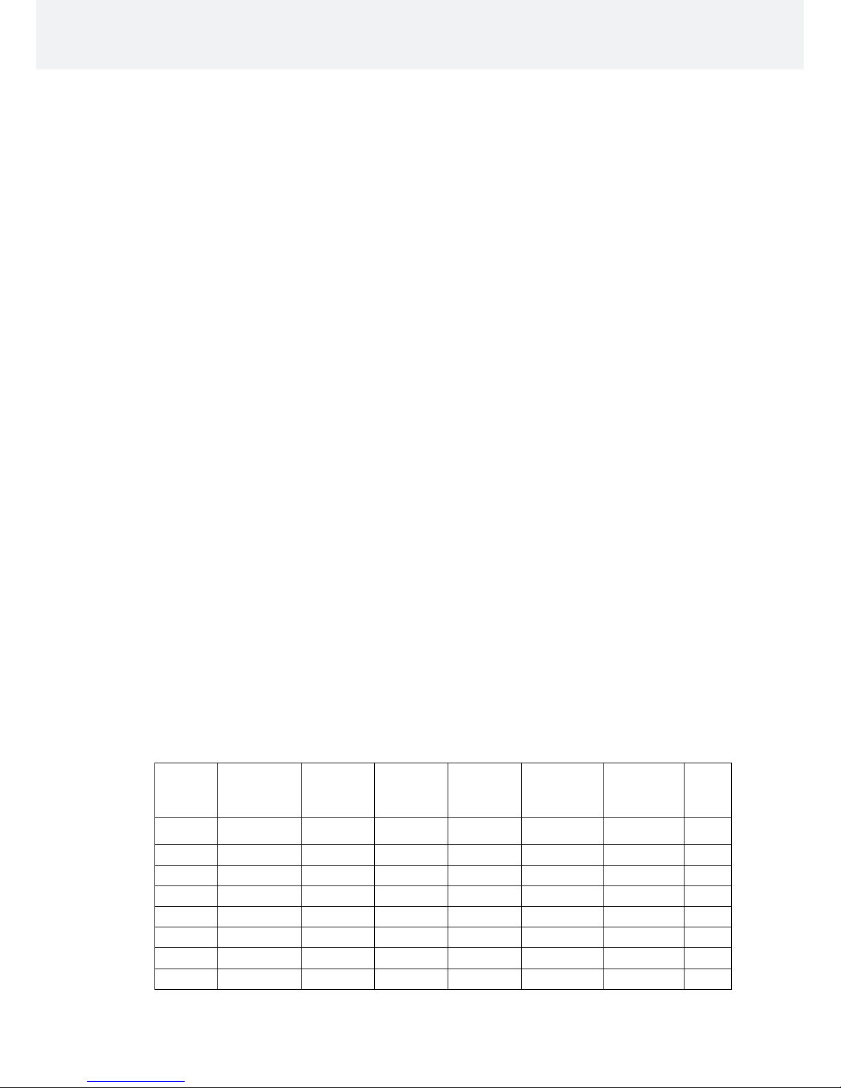
Selecting the steam generator output for the steam room
You can estimate the power requirement using the formula below.
Volume (m
3
) x K1 x K2 = Power requirement (kW)
Forced ventilation K1 = 0.75
No ventilation K1 = 0.52
Acrylic wall K2 = 1.00
Light wall: board + tile K2 = 1.25
Heavy wall: stone, concrete + tile K2 = 1.50
Very heavy wall: stone, concrete + tile K2 = 2.00
In heavy built steam rooms, it is recommended to use e.g. electric heating cable for warming the seats,
walls and floors.
Output Light struc-
ture, acrylic,
tempered
glass
Light board
wall + tile
Heavy wall,
concrete,
stone
Steam
kg / h
kW No A/C Air condi-
tioned
No A/C Air condi-
tioned
No A/C Air condi-
tioned
3,4 2 – 7 m³ 2 – 6 m³ 2 – 6 m³ 2 – 5 m³ 2 – 5 m³ 2 – 4 m³ 5
4,7 3 – 8 m³ 3 – 7 m³ 3 – 7 m³ 2 – 6 m³ 2 – 6 m³ 2 – 5 m³ 6
6,0 4 – 13 m³ 4 – 9 m³ 4 – 8 m³ 3 – 7 m³ 3 – 7 m³ 3 – 6 m³ 8
7,7 6 – 15 m³ 6 – 11 m³ 6 – 10 m³ 5 – 9 m³ 5 – 9 m³ 4 – 8 m³ 10
9,5 9 – 17 m³ 9 – 13 m³ 9 – 14 m³ 8 – 13 m³ 7 – 11 m 6 – 9 m 13
12,0 12 – 24 m³ 11 – 18 m³ 11 – 20 m³ 9 – 16 m³ 9 – 16 m³ 8 – 12 m³ 16
14,0 18 – 30 m³ 14 – 22 m³ 14 – 24 m³ 12 – 18 m³ 11 – 17 m³ 10 – 14 m³ 19
Table for selecting a steam generator based on the steam room volume and wall materials.
User and installation manual HNS–M2
3

General
HNS-M2 steam generators are only intended for use in heating spa facilities. Using steam generators in other areas
than steam rooms can damage the building's structure.
The manufacturer is not responsible for damages caused if the unit has been used incorrectly or in a manner for
which the unit was not designed for.
Water and steam pipe connections must be made prior to connecting the unit into the mains.
Due care and attention must be taken when making the connections. Proper sealing must be ensured for all
extensions. A good extension must have at least taped over threaded connections, but it is recommended that
connections are soldered.
Ventilation
It is not normally necessary to arrange ventilation for steam saunas that are used for less than two hours. steam
rooms that are used for more than two hours at a time need ventilation for functional and hygienic reasons. The
ventilation recommendation is 10 to 20 m
3
per person per hour.
If there is an empty space above the ceiling of the steam room, it must not be completely sealed off. Make at least
one ventilation hole (100 mm x 100 mm) into the empty space, on the same wall with the door.
The Supply air valve may be a hole in the bottom part of the wall with the door or a gap under the door.
The Exhaust valve is placed in the ceiling or on a wall near the ceiling as far from the supply air valve as possible,
however not above the door or the seats. The exhaust valve is connected to an air conditioning channel going
outside
Forced ventilation. If natural ventilation is not adequate (e.g. negative pressure in the room where the fresh air is
taken from), the steam room must be equipped with forced ventilation. Its output must be equivalent of 10 to20 m³ of
ventilation per person per hour.
Testing the water before using the steam generator.
The test packet that comes with the steamer includes test slips, which can be used for testing the water hardness
number as follows:
Dip the test slip in water for about 1 second, take it out and shake off the excess water. After a minute, compare the
colour code appearing on the test slip with the code key in the packet.
Test result: < 3° dH, Very soft water.
> 4° dH, Soft water, Installing the decalcification device recommended
> 7° dH, Medium-hard water, Install decalcification device and retest the water hardness.
> 14° dH, Hard water, Install decalcification device and retest the water hardness.
> 21° dH, Very hard water, Install decalcification device and retest the water hardness.
See page 9 for steam generator's operation time in hours before decalcification
The steam generator must be placed away from water and moisture (dry room). The room must be well ventilated as
the unit also produces heat. The maximum temperature of the room must not exceed 35°C. Recommended minimum
free space to sides and above the steamer is 30 cm. Adequate space for maintenance should also be planned for in
the placement of the unit. There should be a drain nearby for draining the tank.
The steam generator can be installed freestanding on the floor or on the wall using wall fittings. When using wall
fittings, ensure you use appropriate fittings and screws for the type of construction material of your walls. The steam
generator weighs about 17 kg when filled with water.
When the automatic drain valve is used, it is recommended you use wall installation so an adequate angle can be
ensured for draining of water.
User and installation manual HNS–M2
4

Image of principle of installation
1700mm
Locating the control panel Generator wall mounting
Control panel is installed inside or outside the steam room, model HNS – M2.
The cable of the control panel can be extended with an equivalent cable, max 10 m.
The On/Off push button can be used for remote starting and stopping of the steam generator, the push button can be
placed inside or outside the steam room. For more detailed instructions, see page 12
Steam nozzle/nozzles are fitted approximately 200 to 400 mm from the floor underneath a bench or a seat, or onto
the wall so that the hot steam cannot burn anyone's feet. The steam nozzles are aimed towards the floor. When the
nozzles are installed, you must ensure to place them somewhere where nobody can accidentally touch them. The
steam temperature is +100 °C and it can cause injuries on contact.
If children or people with impaired reflexes use the steam room, the steam nozzle must be fitted with a protector that
prevents people from being exposed to the hot steam shower.
Sensor. The sensor is connected with the steam generator circuit board to connectors T1 and T2 which identify it
automtically.
Sensor is installed at about 1,700 mm high, preferably on the wall opposite the door. It is recommended to seal the
sensor installation hole with appropriate sealing material, so that moisture cannot enter the wall structures.
The steam room thermometer is installed at such a height that it shows the same reading as the control panel.
Steamer connections
5
2
0
380
160
Sensor
Control panel
Water connection
Power
supply
Flushing
Steam pipe
Steam room
On/off push button
User and installation manual HNS–M2
5
Water connection, ¾”
Automated electromagnetic valve
plug (HNS-M2)
Water draining ½ ”, manual
or electric valve
Lid nut
for decalcification
Steam pipe ½”
Main switch
Control panel cable
Power supply

Water and steam pipe connections
Connect the flexible ¾” water connection tube in the packaging to the water connection in the installation panel of the
unit and to the cold water piping of the building. The water pressure must be between 0.2 and 10 bars. The water
supply pipe must have a manual stop valve for stopping water supply to the unit, if the unit is not used for a prolonged
time.
Installation must follow local regulations
It is recommended to use at least 18x16 mm (steam generator’s size 3.4 kW-9.5 kW) and 22x20 mm (steam
generator’s size 12.0 kW- 14 kW) copper pipe or a silicone tube of similar type when connecting the steam pipe. The
steam pipe diameter must be the same for the whole length.
The steam pipe must be tilted upwards or downwards from the steam generator to the steam room. There MUST
NOT be any water seals or water pockets. The condensation water forming in the steam pipe must be allowed to
drain freely to the steam room or back to the generator. If a fragrance pump is connected to the generator, the pipe
must ALWAYS drain away from the steamer, so that the chemicals cannot get into the tank.
Recommended maximum length for the steam pipe is 5 metres.
It is recommended to always use additional insulation for the steam pipe, for both safety reasons and to prevent
water condensation in the pipe.
Clearance from an uninsulated steam pipe to flammable material such as wood must be at least 10 mm.
WARNING: Hot steam can cause burn injuries.
The electromagnetic valve designed for discharging water from the steam generator tank (accessory: Automatic drain
valve) is installed on the downpipe, alternatively use manual flushing valve. Connect the downpipe (copper pipe with
a minimum diameter of 16 mm) to the downpipe of the steam generator. The downpipe is led to the nearest drain
outside the steam room. The temperature of the discharge water is 90–95 C.
IMPORTANT! No stoppers (valves, taps, etc.) may be fitted on the downpipe.
Regardless of where the downpipe is led, it must fall all the way from the steam generator to the drain. To ensure
adequate fall, you may have to place the steam generator on a wall mount or on a stand.
The steamer generator’s tank should be drained after each use. This extends the life cycle of the appliance
and reduces scaling and the need for repair.
The product’s warranty will be void if the steam generator has been incorrectly installed or it has been used
in a manner other than described in the user manual.
The warranty also expressly excludes operational faults if they are caused by hard water i.e. water with high
levels of chalk, or otherwise impure water.
The steam generator must be maintained as described in the user manual.
User and installation manual HNS–M2
6
 Loading...