

Helo 1712-45-1706, 1712-60-1706, 1712-80-1706 Installation And Operating Instructions Manual

INSTALLATION AND OPERATING INSTRUCTIONS
Designer “Trend" Series Sauna Heaters
Models 4.5, 6.0, 8.0
(Type #'s 1712-45-1706, 1712-60-1706, 1712-80-1706)
with Trend Control (Type # 1601-31 and 1601-31-1).
Page 1
WARNING
Do not take a sauna if using
alcohol, drugs or
medications.
Pregnant women or persons
with poor health should
consult their physician before
using any sauna.
Caution re hazard: Do not
use the sauna room for
drying clothes, bathing suits,
etc. Do not hang towels
above heater or place any
object other than the rocks
supplied on the heater. If any
darkening of the wall around
the heater is noticed
discontinue sauna use
immediately.
Read all instructions carefully before installation. Please leave all
instructions and warranty with the owner.
WARNING
Prolonged exposure to elevated temperatures is capable of inducing
hyperthermia. Hyperthermia occurs when the internal temperature of the
body reaches several degrees above the normal body temperature of
98.6°F. The symptoms of hyperthermia include an increase in the normal
temperature of the body, dizziness, lethargy, drowsiness, and fainting. The
effects of the hyperthermia include failure to perceive heat, failure to
recognize the need to exit the room, unawareness of impending hazard,
fetal damage in pregnant women, physical inability to exit the room and
unconsciousness.
WARNING
The use of alcohol, drugs, or medication is capable of greatly increasing
the risk of fatal hyperthermia.
SECTION 1: GENERAL INFORMATION
These heaters are ETL approved by Intertek for permanent installations and
electrical connections. Built with splash proof construction, the conducting
parts are protected against water. All wiring must be performed in
accordance with national and local codes. See Diagram 2 for wire and
room size requirements. These heaters are wall mounted.
Inspect sauna regularly for
required maintenance to
heater, control and benches.
Replace wood surfaces
which show any signs of
deterioration.
The heater gets extremely hot
during operation and should
not be touched or burns may
result.
Minors should be adequately
supervised whenever near a
hot or warming sauna.
72-0106 01-07-16 7013482 314 SKSM 215 A

INSTALLATION AND OPERATING INSTRUCTIONS
"A"
DISTANCE
"B"
DISTANCE
"C"
DISTANCE
"D"
DISTANCE
"K"
DISTANCE
Designer 4.5 3.0" 3 5/8" 4.0"
11 1/2"
23"
Designer 6.0
4.0" 4 5/8" 5.0" 11 1/2"
23"
Designer 8.0
5.0" 5 5/8" 6.0" 11 1/2"
23"
HEATER
MINIMUM
WIRE SIZE
Floor Area
Ceiling
Height
Volume
Cu.Ft.
Ceiling
Height
Volume
Cu.Ft.
Power Supply
to Heater
1 208 21.6 2 #10AWG+GR
1 240 18.8 2 #10AWG+GR
3 208 12.5 3 #12AWG+GR
3 240 10.8 3 #12AWG+GR
1 208 28.8 2 #8AWG+GR
1 240 25 2 #10AWG+GR
3 208 16.7 3 #12AWG+GR
3 240 14.4 3 #12AWG+GR
1 208 38.5 2 #8AWG+GR
1 240 33.3 2 #8AWG+GR
3 208 22.2 3 #10AWG+GR
3 240 19.2 3 #10AWG+GR
AMPS
Light
Circuit
Supply
Designer
Trend 4.5
1712-45-1706
4.5 12 sq. ft. 74" 100 96" 210
S
e
e
N
o
t
e
1
B
e
l
o
w
HEATER
MODEL /
Product
Number KW
MINIMUM ROOM MAXIMUM ROOM
PHASE VAC
310
Designer
Trend 8.0
1712-80-1706
8.0 31 sq. ft. 74" 250 96" 425
Designer
Trend 6.0
1712-60-1706
6.0 21 sq. ft. 74" 175 96"
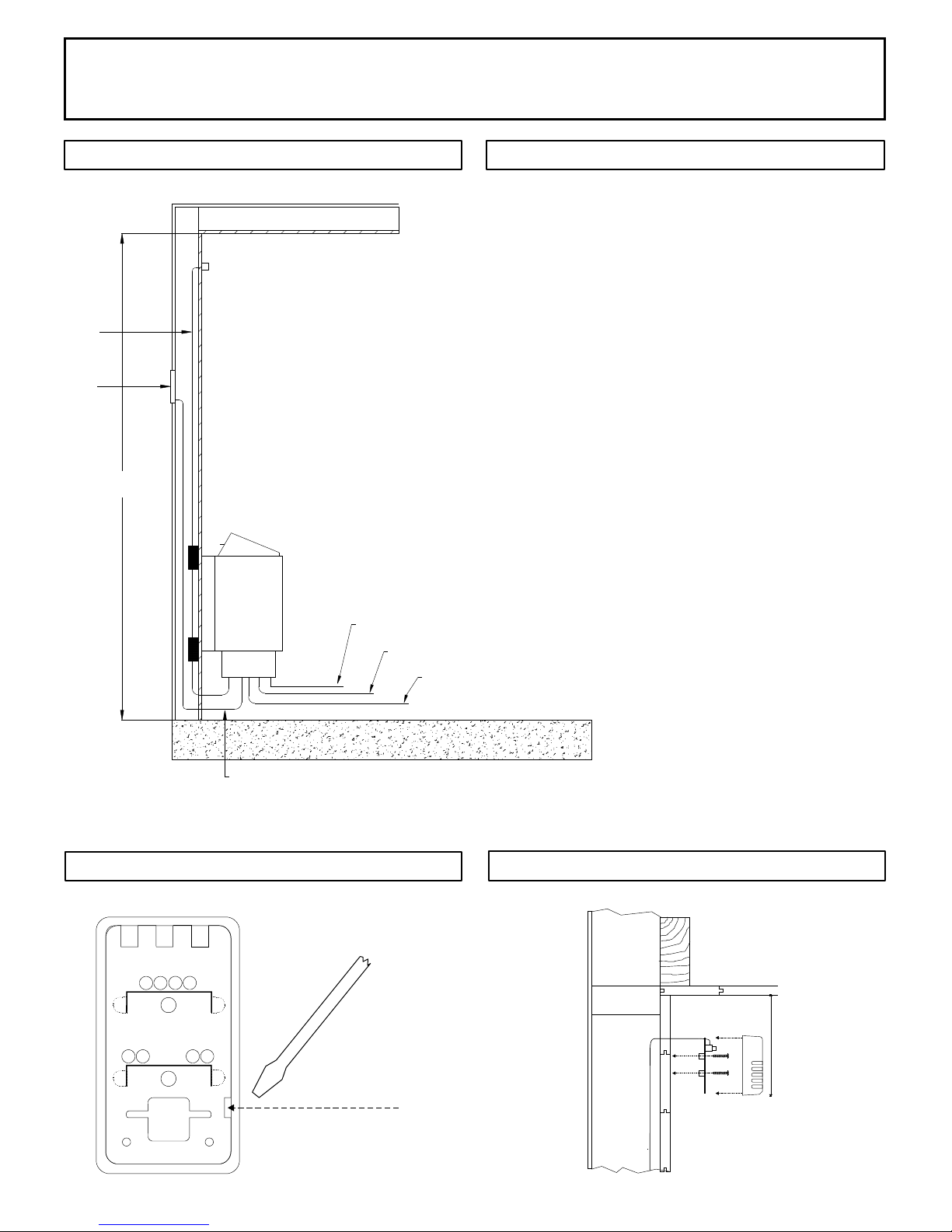
DIAGRAM 1
MOUNTING BRACKET LOCATION AND MINIMUM DISTANCE TO COMBUSTIBLE MATERIAL
Page 2
Temperature
5"
Sensor
14 3/8"
B
6"
K
Min.
A
Use the long screws in the upper
holes of the mounting bracket
10½"
6½"
Recheck your distances from the heater to
combustible materials to be sure you have
the proper minimum distances.
Screws
D
C
44"
(Upper Bench)
Minimum
2"
1"
Guard
Rail
18½"
High Limit Control
OBSERVING MINIMUM DISTANCES IS REQUIRED
TO REDUCE THE RISK OF FIRE
74"
Minimum
NOTE 1: Use separate 120 volt branch circuit protected for 15 amps if control switch is to be used for lighting.
72-0106 01-07-16 7013482 314 SKSM 215 A
DIAGRAM 2
INSTALLATION AND OPERATING INSTRUCTIONS
Page 3
SECTION 2: MOUNTING OF SAUNA HEATER
HANGING THE HEATER Using the template provided, drill four 9/64" holes to
fasten the heater to the wall. Install two ¼" x 1 ½" hex head lag screws (supplied
with the heater) into the upper two holes. Tighten these screws until their heads
are about 1/8" from the wall surface. The screws must be threaded through the
wall into a framing member or backing board to support the heater weight. Hang
the heater on the two upper screws. Locate the two ¼" x 1" hex head lag screws
(supplied with the heater) then install them into the two lower mounting holes.
Tighten to lock the heater in place. See Diagram 1 for the heater location details
and the necessary clearances to combustible materials.
SECTION 3: PLACING OF ROCKS (SEE DIAGRAM #10)
The rocks supplied with the heater have been chosen to provide the best heater
performance. Use of any other type of rock may void the heaters warranty. Never
operate the heater without rocks in place! Rinse the rocks with water before
placing in the heater. Carefully place the rocks loosely so that the air can circulate
through the heater. Packing the rocks too tightly may cause the heater high limit
switch to trip. The rocks must fully cover the heating elements. Attach the guard
with the screws provided.
SECTION 4: ELECTRICAL HOOK-UP
Electrical installation must be made by a licensed electrician in accordance with
the National Electrical Code and local regulations.
WARNING
Fire sprinkler systems used
inside any sauna room should
be properly rated for sauna
room temperatures.
Do not pour chlorinated pool
or spa water on heater.
Excessive water use on heater
may cause damage and void
warranty.
Electric Shock Hazard - High
voltage exists within this
equipment. There are no user
serviceable parts in this
equipment. All installation
and service to this equipment
should be performed by
qualied licensed personnel
in accordance with local and
national codes.
- NOTE: A GFCI (Ground Fault Interrupt Circuit) device is not required by ETL. A
GFCI may be installed if required by local codes but will nuisance trip during use of
the product. - CAUTION: Loose wire connections can cause heat damage to wires,
terminal blocks and other components and may void the warranty.
Remove the screws from the left and right sides of the electrical box. Remove the
painted trim piece from the front of the box. Route the feed wires through the holes
provided in the bottom of the heater and connect the wires to the terminal block.
To determine the correct wire size, refer to Diagram 2. Use copper supply wire
only, suitable for minimum 90 degrees C. The heater must be grounded! See
Diagram 6 for proper connections.
SECTION 5: TEMPERATURE SENSOR
Feed the "low voltage" sensor wire from the sensor to the sauna heater location.
Sensor wire must be routed completely separate (as per low voltage electrical
wiring codes) from any wiring carrying over 50 volts. It may be necessary to drill
holes to string the wire through the studs or ceiling joists. Route the wire to bottom
of the heater and connect to the sensor connection. Mount sensor to nished wall
5" from the ceiling directly above the heater using two (2) screws (provided) as
shown in diagrams 1, 3 & 5.
SECTION 6: HEATER SCREEN (GUARD RAIL)
Do not construct sauna room
so as to restrict air ow
through the bottom of the
heater.
Packing the rocks too tightly
may cause the heater high
limit switch to trip.
Install a wooden heater guard to prevent the sauna bather from accidentally
touching the sauna heater. Install the heater guard rail with the dimensions shown
in Diagram 1 & 8.
72-0106 01-07-16 7013482 314 SKSM 215 A
INSTALLATION AND OPERATING INSTRUCTIONS
Page 4
Sensor
Wire
Control
Maximum
ceiling
spacing
74"
DIAGRAM 3
Sensor protective cover. Locate bottom of
sensor 5" from ceiling and directly above
of heater.
DIAGRAM 4
Diagram 4 was intentionally left blank.
Heater Input
Light Input
Light Output Power
15' Low Voltage Cable provided with control.
DIAGRAM 5
Back of
sensor
DIAGRAM 5, continued
Insert screwdriver tip here to unsnap
sensor cover from sensor.
Note vertical orientation of cover
before removing.
72-0106 01-07-16 7013482 314 SKSM 215 A
5" from ceiling to
top of sensor and
centered above
the heater.
 Loading...