

Helo 1105- 901-0104, 1105-1051-0104, 1105-1201-0104, 1105-1501-0104, 0518-2-151704 User Manual
STEAMY SAUNA HEATER: 1105- 901-0104
1105-1051-0104
1105-1201-0104
1105-1501-0104
CONTROL PANEL: 0518-2-151704
7013933
314 SKLE 44 D
2
USING.
Before you start to install and use the sauna heater check the following:
- that you have got all the parts needed.
- check that the voltage of the heater and the control box is the right one and that the
control box suits your heater.
- chech that the effect of the heater suits your sauna. You must not exceed or go be low the volumes mentioned in table 1.
- look at the installation distances in table. 1. You have to follow these, otherwise it can
cause a burn.
- study these installation- and using instructions carefully.
HOW TO CHOOSE THE EFFECT OF THE HEATER.
Noticing the volume of the sauna you choose the effect of the heater according to
table 1.
The volumes mentioned in table 1 are valid under the assumption that the sauna is
well insulated. If there are walls of bricks or concrete in the sauna you have to add to
the volume about 1,2m2 for every brick- or concerete wall m3 and then you choose the
effect of the heater according to the composed volumes.
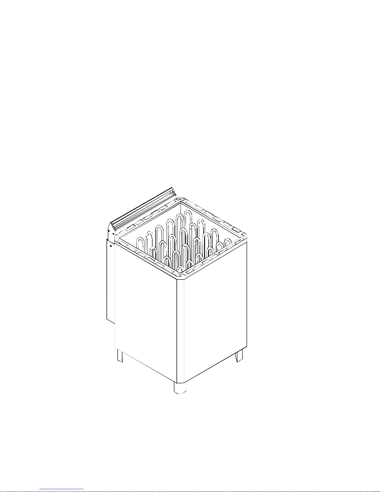
MOUNTING OF THE SAUNA HEATER
The sauna heaters are freestanding models and these heaters must be firmly fastened
to the floor by screwbolts through two of the feet. When fastening the heater to the
floor please follow the requirements about the minimum distances to combustible material indicated on the name plate of the heater and in table 1 and fig. 1. The sauna
heater can be placed on a wooden floor. Do not protect the wall behind the heater with
for instance asbest- or eternite plates, as these may cause a too high temperature
increase in the wall.
Do not place the sauna heater in a nisch, and you must not have a compact quard rail
around the heater. Draught from door, vents etc. should be avoided as this effects the
thermostat.
QUARD RAIL
If you put a quard rail around the heater you have to note the minimum distances
mentioned in table 1.
MOUNTING OF THE CONTROL BOX
The control box must be installed in a dry place outside the sauna room. The sensor
unit should be fastened to the wall in the sauna according to fig 1. please follow the
measurements mentioned in fig 1. otherwise it may cause a burn.
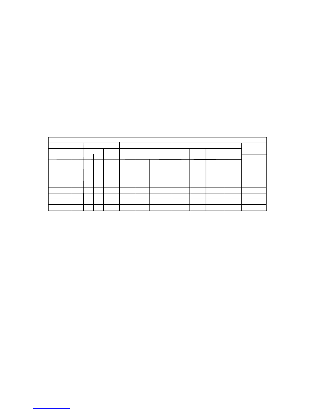
TABLE 1.
HEATER SAUNA MINIMUM DISTANCES CABLES TO FUSES CONTROL
Type Effect Volume Height From heater to Control Sensor Steamy Main PANEL
Min. Max Min panel unit unit fuse
side- cei- quard rail HO7BB and ling and upper F5G
bench
Hmin A min B min C min
kW m m mm mm mm mm mm mm mm A
1105-.. 9,0 8 12 1900 80 1200 80 6 x 1,5 4 x 0,5 5 x 2,5 16 X
1105-.. 10,5 9 15 1900 80 1200 80 6 x 1,5 4 x 0,5 5 x 2,5 16 X
1105-.. 12,0 10 18 2100 120 1400 120 6 x 1,5 4 x 0,5 5 x 4 20 X
1105-.. 15,0 14 24 2100 120 1400 120 6 x 1,5 4 x 0,5 5 x 6 25 X
backwall
0518-2-151704
3 3 2 2 2

3
SENSOR UNIT
The sensor unit should be plased in accordance with the measures stipulated in fig. 1.
The sensor unit is provided with long heat resisting (T170 C) 4x0,5mm cables. These
cables can be extended by a normal weak current cables. For connection of the sensor
unit control panel, please see fig. 4.
CONNECTION
The electrical installation of the sauna heater and the control panel must be made by a
qualified electrician according to the requirements. The principal connection will be
made in accordance with fig. 1. The required wiring diagrams are inside the heater and
the control panel. The heater can be connected by using a rupper wire HO7BB-F5G,
table 1. the connection box must be a splash water proof construction and its height
from the floor must not be higher than 500mm. If the connection- and installationwires
come inside the sauna or inside the walls of the sauna higher than 1000mm from the
floor they must loaded take at least 170 oC (for instance HO7SS-K4G)
All electrical appliances that are installed higher than 1000mm from the sauna floor must
be accepted for use in 125 oC surrounding temperatures (marking T 125).
SAUNA STONES
Since the sauna stones may be dusty, we recommend that they are rinsed before being
placed in the rock compartement. Put the largest stones at the bottom. Do not pack the
stones tight but place them to allow good air circulation. To prevent damage to the sauna unit, the stones must be replaced if they begin to flake.
THE VENTILATION OF THE SAUNA
The ventilation of the sauna must be sufficient. In a private sauna the air should be
changed 6 times an hour. This can be achieved by a vent under the heater from an
adjacent area. The diameter of the vent should be at least 6cm (fig.2). The exhaust
must be situated lower than the upper benches as far as possible from the heater and
about 500-600mm higher than the fresh air vent.The exhaust must be twice the size of
the fresh air vent. From the exaust the consumed air will be lead upwards to the ventilation opening, which must be at the level of the ceiling. In order to facilitate the ventilation of the sauna after the bathing there must be a ventilator at the ventilation opening. This ventilator must be shut during the heating of the sauna and during the bathing. The exhaust pipe can also in order to save place be placed in a corner under the
wood framing.
LIMIT CONTROL
Inside the thermostat there is a thermal cut-off that switches off the whole current if the
temperature for some reason rises too high in the sauna. After reaching a normal temperature in the sauna the thermal cut-off can be renewed.
Before that you have to find the reason for the temperature increase.
 Loading...