

Page 1
Quick Start Guide WALL IE
Version
en
10
as of FW 1.08
www.helmholz.com
Page 2

Contents
1. Introduction 3
2. Connection 4
3. Initial access to the web interface 4
4. Overview 5
5. Choosing the operating mode 6
6. Application case “NAT” 7
7. Bridge mode 16
8. MAC address ltering 21
9. Firmware update 22
10. Resetting to factory settings 23
11. LED status information 23
12. Button functions 23
13. Technical data 24
Note:
Our products contain open source software, among others. This software is subject to the respectively relevant license conditions. The corresponding licensing conditions, including
a copy of the complete license text, will be sent to you with the product. They are also provided in our download area of the respective products under www.helmholz.com. We also
offer to send you the complete corresponding source text of the respective open source software for an at-cost fee of 10 Euro as a DVD to you or a third parts at your request. This offer
is valid for a period of three years, starting from the date of product delivery.
Quick Start Guide WALL IE2
Page 3
1. Introduction
Please note: Please observe the safety instructions for the product, which can be found
in the manual. The manual can be downloaded from the website www.helmholz.com in
the download area.
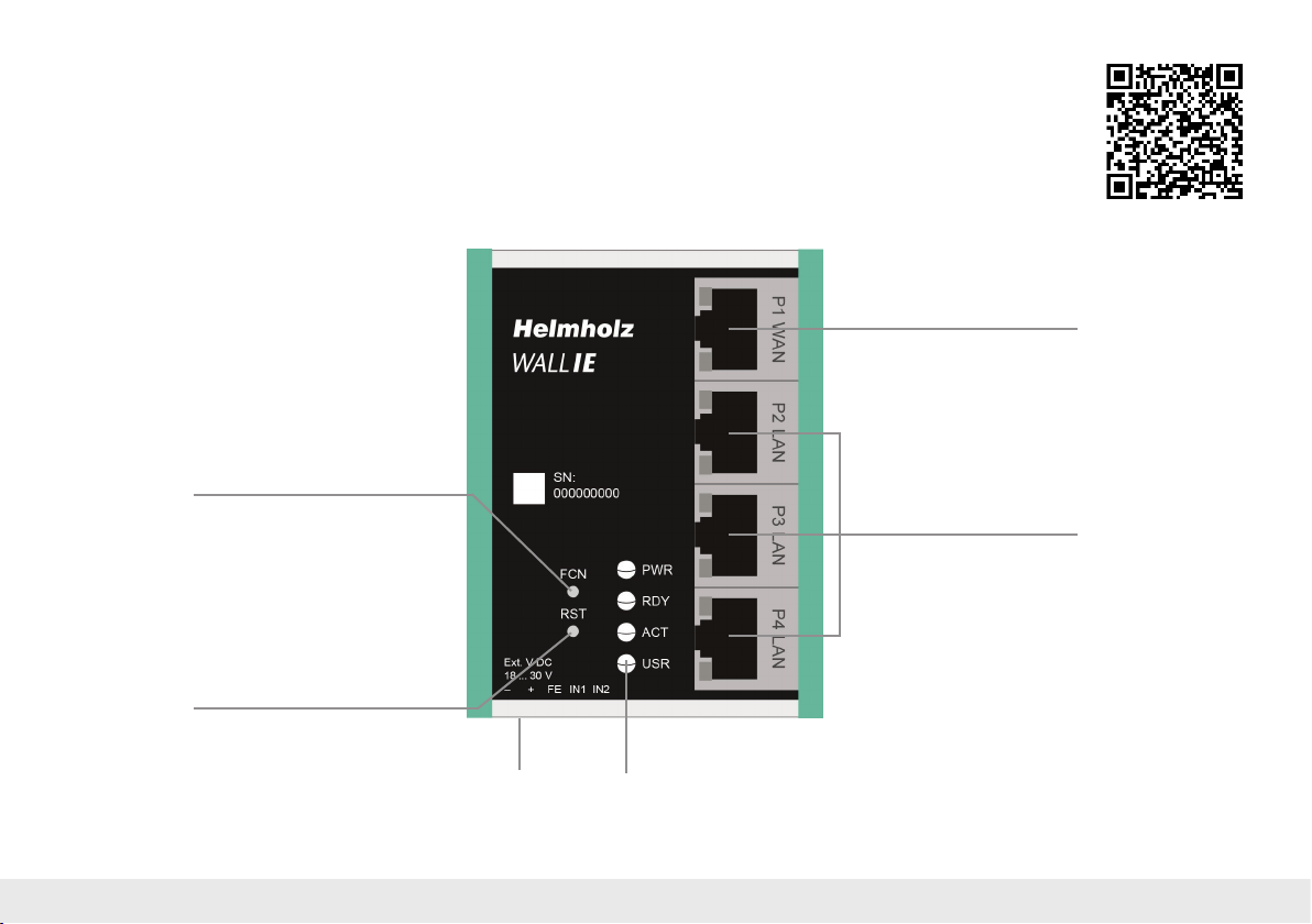
FCN: Function button
RST: Reset button
This document explains the initial commissioning of the
WALL IE using the application examples “NAT” and “Bridge”.
Only the most important settings will be explained.
You can nd a detailed description of all settings in the
WALL IE manual.
P1: WAN port
P2–P4: LAN ports
Voltage supply
Quick Start Guide WALL IE 3
Operation LEDs (see page 23)
Page 4
2. Connection
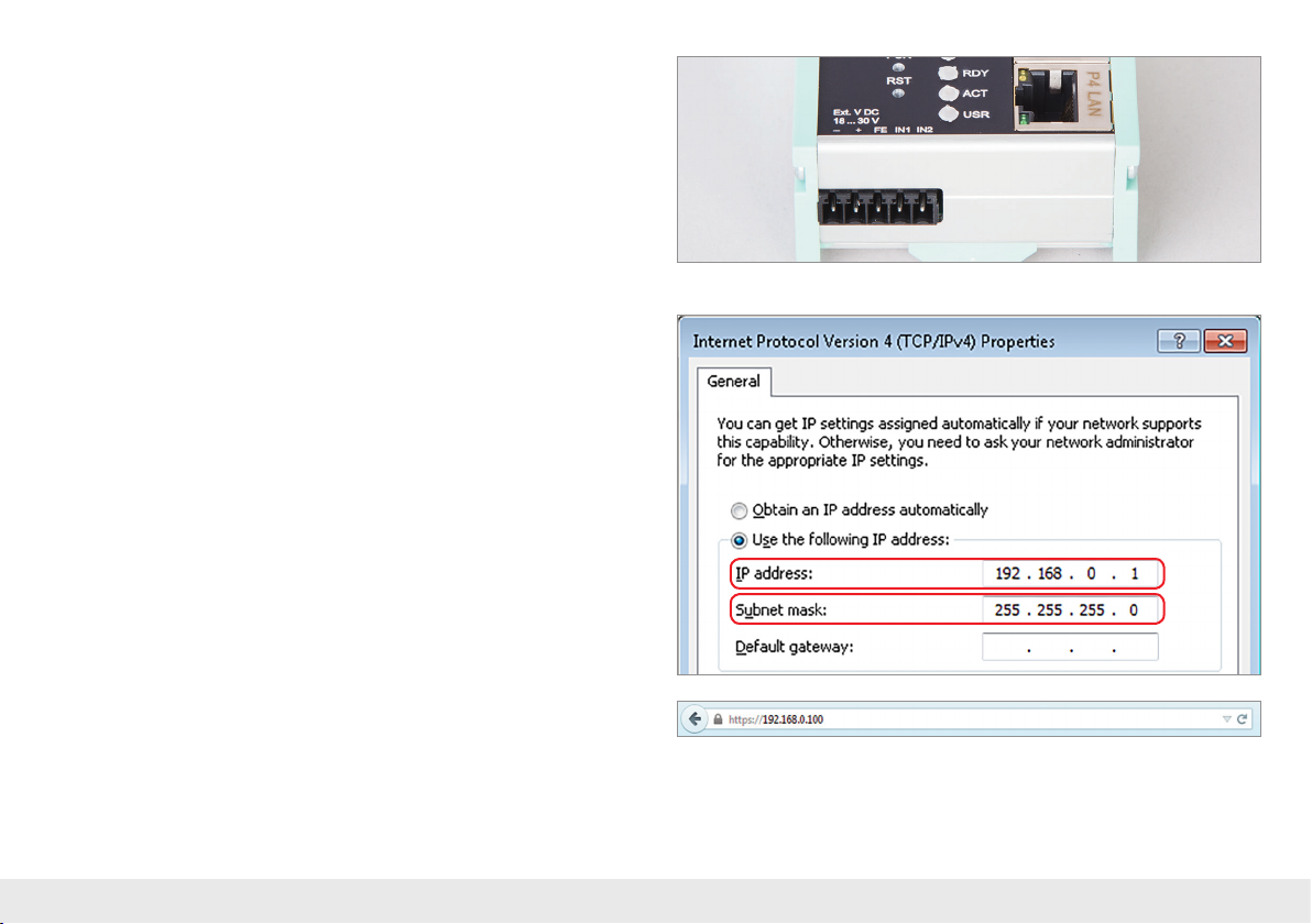
The WALL IE must be supplied with 24 V DC at the wide range input 18–30 V DC via
the provided connector. Connection FE is for the functional ground. Connect this
correctly with the reference potential.
The RJ45 “P1 WAN” socket is for the connection of the external network. The RJ45
“P2 LAN –P4 LAN” sockets are switched and are for the connection of the internal
network.
3. Initial access to the web interface
The WALL IE is set on the LAN-side at the factory with the IP address 192.168.0.100
and the subnet mask 255.255.255.0. Access to the web interface is only possible via
the LAN connections P2–P4.
The IP address of your network adapter must rst be set in accordance with the IP
subnet of the WALL IE.
Now connect a patch cable with the LAN connection of your PC and one of the
LAN ports P2–P4 of the WALL IE. The web interface can be reached in the delivery
condition by calling up https://192.168.0.100 in the browser page.
Note: For security reasons, the web interface can only be reached through a secured
HTTPS connection. In order to reach the website, an exception must be conrmed once
in the browser.
An own certicate for the connection backup can be stored in the “Device/HTTPS”
menu as needed.
Quick Start Guide WALL IE4
Page 5
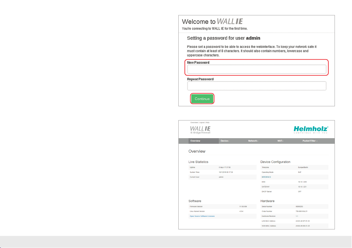
With the rst login you will be requested to set a password for the “admin” user.
The password must have at least 8 characters and may have a maximum of 128
characters. It may contain special characters and numbers. With the “Continue”
button, the password is stored in the device and you will be forwarded to the
“Overview” page of the WALL IE.
The main user is always “admin”.
In addition to the main user, the “it-user” and “machine-user” can also be used
with limited rights. The users can be activated and the afliated passwords set in
the “Device/Password” menu.
Note: Please note the password well! For security reasons, there is no possibility to
reset the password without setting the device to the factory settings.
4. Overview
The “Overview” website of the WALL IE always opens after the login.
This contains a menu bar in the upper section and an overview of the status,
the system information, and the basic settings of the WALL IE beneath them.
Note: Please check at the website of the WALL IE under www.helmholz.com for a
newer rmware version. The rmware update is described on page 22.
Quick Start Guide WALL IE 5
Page 6
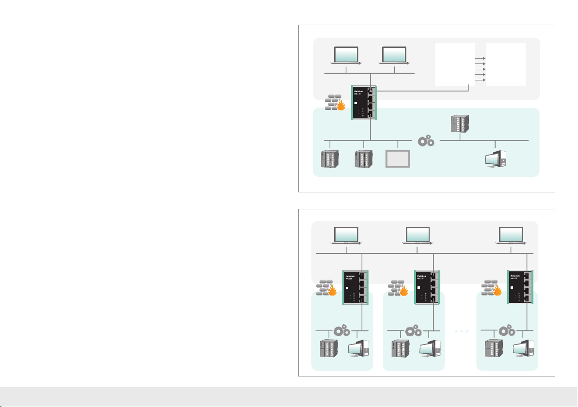
5. Choosing the operating mode
Depending upon the application case for the WALL IE, the operating mode must
rst be dened. WALL IE supports two principal operating modes:
NAT and Bridge.
5.1. The NAT operating mode
When an automation cell with preset IP addresses is to be incorporated into a
production network with other IP addresses, the IP addresses of the machine must
normally all be set again.
When using Network Address Translation (NAT), WALL IE offers the possibility to
leave the IP addresses of the machine as they are, but to enable communication with
the machine network with own IP addresses from the production network.
In the NAT operating mode, WALL IE forwards the data transfer between various IPv4
networks (Layer 3) and implements the IP addresses with the help of NAT.
Packet lters and MAC address lters can be used to limit the permitted data transmission.
Broadcast trafc is generally ltered at the WALL IE, which means that the time behavior of the machine network is not impaired by the production network.
Basic NAT, also known as “1:1 NAT” or “Static NAT”, is the translation of individual
IP addresses or of complete IP address ranges.
With the help of port forwarding, it is possible as an alternative to congure that
packets be forwarded to a particular TCP/UDP port of the WALL IE to a certain participant in the machine network (LAN).
The NAT operating mode thus also allows the integration of several automation cells
that use an identical IP address range into the same production network.
Each automation cell can be assigned various, free IP addresses from the production
network.
If “NAT” is your planned application case, please continue reading on page 7.
Company network
10.10.1.10 10.10.1.20
External (WAN)
SN:
000000000
P3 LAN
PWR
FCN
RDY
P4 LANP1 WAN P2 LAN
RST
ACT
Ext. V DC
USR
Internal (LAN)
18 ... 30 V
+FEIN1IN2–
0
0
0
1
1
1
2
2
2
3
3
3
4
4
4
5
5
5
6
6
6
7
7
7
0
0
1
1
2
2
3
3
4
4
5
5
6
6
7
7
192.168.10.1 192.168.10.2 192.168.10.50 192.168.10.100
0
0
0
1
1
1
2
2
2
3
3
3
4
4
4
5
5
5
6
6
6
7
7
7
0
0
1
1
2
2
3
3
4
4
5
5
6
6
7
7
External IP
10.10.1.11
10.10.1.12
10.10.1.13
10.10.1.14
10.10.1.15
192.168.10.5
0
1
2
3
4
5
6
7
0
0
1
1
2
2
3
3
4
4
5
5
6
6
7
7
0
0
1
1
2
2
3
3
4
4
5
5
6
6
7
7
10.10.1.0/24
Internal IP
192.168.10.1
192.168.10.2
192.168.10.5
192.168.10.50
192.168.10.100
Machine network192.168.10.0/24
10.10.1.0/24
Machine X
External
Ext. V DC
18 ... 30 V
Internal
Machine 1
Company network
External
Ext. V DC
18 ... 30 V
+FEIN1IN2–
Internal
Machine 2
SN:
000000000
P3 LAN
PWR
FCN
RDY
P4 LANP1 WAN P2 LAN
RST
ACT
USR
SN:
000000000
P3 LAN
PWR
FCN
RDY
P4 LANP1 WAN P2 LAN
RST
ACT
USR
+FEIN1IN2–
External
SN:
000000000
FCN
RST
Ext. V DC
18 ... 30 V
+FEIN1IN2–
Internal
P3 LAN
PWR
RDY
P4 LANP1 WAN P2 LAN
ACT
USR
0
0
0
1
1
1
2
2
2
3
3
3
4
4
4
5
5
5
6
6
6
7
7
7
0
0
1
1
2
2
3
3
4
4
5
5
6
6
7
7
192.168.10.0/24
0
0
0
1
1
1
2
2
2
3
3
3
4
4
4
5
5
5
6
6
6
7
7
7
0
0
1
1
2
2
3
3
4
4
5
5
6
6
7
7
192.168.10.0/24
0
0
1
1
2
2
3
3
4
4
5
5
6
6
7
7
0
1
2
3
4
5
6
7
192.168.10.0/24
Quick Start Guide WALL IE6
0
1
2
3
4
5
6
7
0
1
2
3
4
5
6
7
Page 7
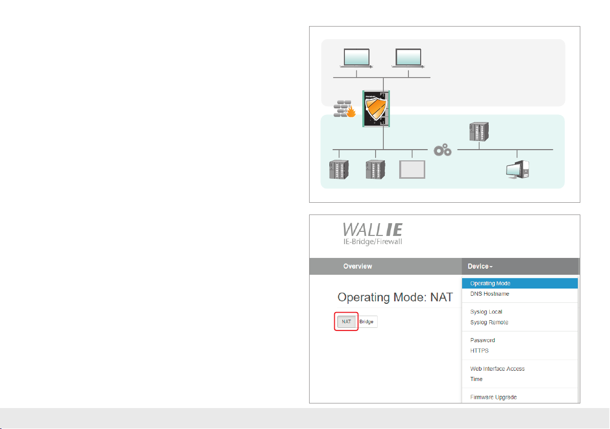
5.2. The Bridge operating mode
In the bridge operating mode, WALL IE behaves like a layer 2 switch between the
machine network (automation cell) and the production network. The IP addresses in
the production network are in this case in the same IP address space (subnet mask)
as the addresses in the machine network.
Access between the two network areas can be limited or secured with packet lters
and MAC address lters.
This enables the separation of a part of the production network without the use of
different network addresses.
If “Bridge” is your planned application case, please continue reading on page 16.
10.10.1.10 10 .10.1.20
External (WAN)
SN:
000000000
P3 LAN
PWR
FCN
RDY
P4 LANP1 WAN P2 LAN
RST
ACT
Ext. V DC
USR
18 ... 30 V
Internal (LAN)
+FEIN1IN2–
Company network
10.10.1.32
0
1
2
3
4
5
6
7
10.10.1.0/24
0
0
1
1
2
2
3
3
4
4
5
5
6
6
7
7
0
0
1
1
2
2
3
3
4
4
5
5
6
6
7
7
0
0
0
1
1
1
2
2
2
3
3
3
4
4
4
5
5
5
6
6
6
7
7
7
0
0
1
1
2
2
3
3
4
4
5
5
6
6
7
7
10.10.1.30 10.10.1.31 10.1 0.1.50 10.10.1.100
0
0
0
1
1
1
2
2
2
3
3
3
4
4
4
5
5
5
6
6
6
7
7
7
0
0
1
1
2
2
3
3
4
4
5
5
6
6
7
7
Machine network10.10.1.0/24
6. Application case “NAT”
To activate the NAT operating mode, select the “Operating Mode” menu point in the
“Device” menu and set this to “NAT”.
Quick Start Guide WALL IE 7
Page 8
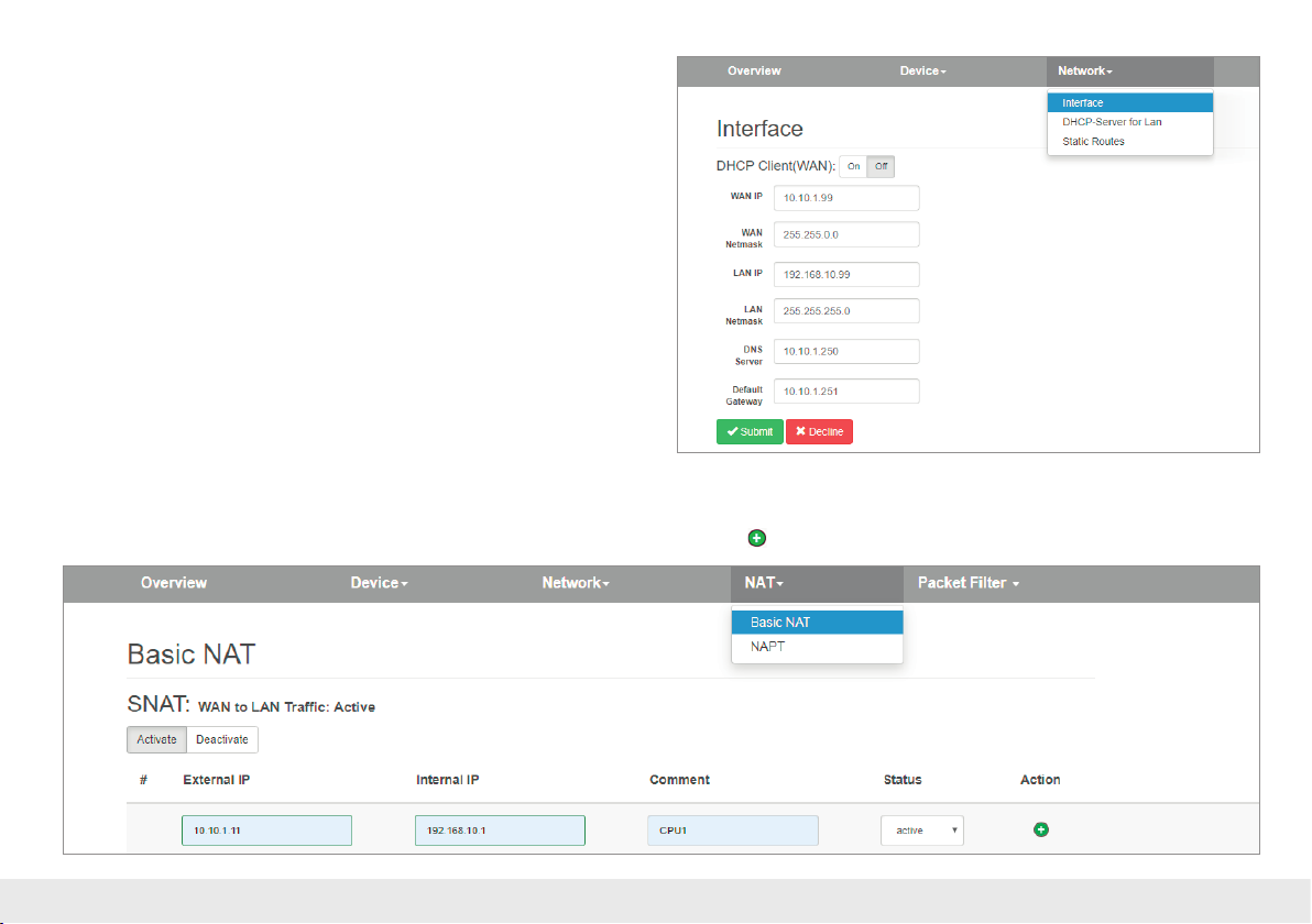
6.1. Adjustment of the IP addresses in the NAT operating mode
Click on the “Network” menu and select the sub-menu “Interface”. The IP addresses
of the WALL IE in the WAN and in the LAN (“WAN IP”/”LAN IP”), as well as the afliated subnet masks (“WAN netmask”/LAN netmask”) can be dened here.
A DNS server and a default gateway can also be indicated.
This is necessary when devices from the LAN should reach the Internet via the
WALL IE. If these are not indicated, then communication of devices in the LAN with
the Internet is prevented.
Optionally, the WAN-IP settings, the DNS server, and the standard gateway can also
be acquired per DHCP.
The entry is saved with the “Submit” button and the IP settings are then activated
immediately.
Note: When you change the LAN IP address, you may need to reopen the website of the
WALL IE in the browser under the new IP address and log in again.
6.2. Setting up “Basic NAT” rules
In order that the entry of “Basic NAT” rules is possible, WALL IE must be in the operating mode “NAT”.
Then select the “NAT” menu and the sub-menu “Basic NAT”. Enter the rst rule and save it with the
button.
Quick Start Guide WALL IE8
Page 9
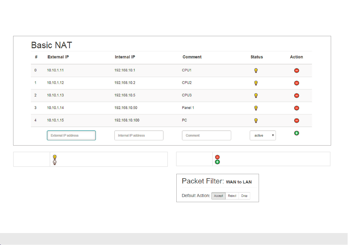
The “External IP” is the IP address under which the network participant of the machine becomes visible in the production network (WAN). The “Internal IP” is the IP address of
the network participant in the machine (LAN). Any text can be entered as a comment.
Each entry is conrmed with the message “Rule added successfully”.
Status
Important: In the case of a “Basic NAT” rule, all ports for “WAN to LAN” data transfer
are initially blocked for this rule for security reasons!
In order to enable access, packet lter rules must be created or the “Default Action” for
the packet lters be set to “Accept”. See the following chapter.
Quick Start Guide WALL IE 9
Rule active (a click on the lamp changes the status).
Rule active (a click on the lamp changes the status).
Action
Deletes a rule.
Adds a rule.
Page 10
6.3. Packet lter “WAN to LAN”
The packet lters enable the limitation of access between the production network
(WAN) and the machine network (LAN).
It can, for example, be congured that only certain participants from the production
network may exchange data with dened participants from the automation cell.
The following lter criteria on layers 3 and 4 are available: IPv4 addresses, protocol
(TCP/UDP), and ports.
Note: The packet lters are always also available in the direction “LAN to WAN”,
see page 13.
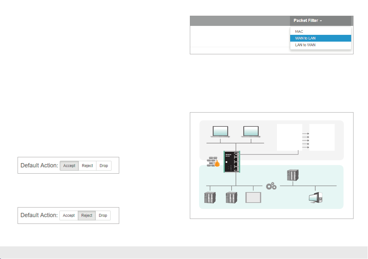
Select the “WAN to LAN” menu point in the “Packet Filter” menu.
With the “Default Option”, you can set whether all frames are generally allowed
(“Accept”) and only special packets are ltered (“Blacklisting”), or whether all frames
are generally prohibited (“Reject” / “Drop”) and only those frames are allowed to
pass through that correspond with the lter rules (“Whitelisting”).
If you initially don’t wish to lter, set the default action to “Accept”.
In order to limit access to the machine network to certain participants in the WAN,
set the default action to “Reject” or “Drop”. In the case of prohibited frames from the
WAN, “Reject” sends an error message in response, while “Drop” rejects the frame
without sending an error message.
Company network
10.10.1.10 10.10.1.20
External (WAN)
SN:
000000000
P3 LAN
PWR
FCN
RDY
P4 LANP1 WAN P2 LAN
RST
ACT
Ext. V DC
USR
Internal (LAN)
18 ... 30 V
+FEIN1IN2–
0
0
0
1
1
1
2
2
2
3
3
3
4
4
4
5
5
5
6
6
6
7
7
7
0
0
1
1
2
2
3
3
4
4
5
5
6
6
7
7
192.168.10.1 192.168.10.2 192.168.10.50 192.168.10.100
0
0
0
1
1
1
2
2
2
3
3
3
4
4
4
5
5
5
6
6
6
7
7
7
0
0
1
1
2
2
3
3
4
4
5
5
6
6
7
7
External IP
10.10.1.11
10.10.1.12
10.10.1.13
10.10.1.14
10.10.1.15
192.168.10.5
0
1
2
3
4
5
6
7
0
0
1
1
2
2
3
3
4
4
5
5
6
6
7
7
0
0
1
1
2
2
3
3
4
4
5
5
6
6
7
7
10.10.1.0/24
Internal IP
192.168.10.1
192.168.10.2
192.168.10.5
192.168.10.50
192.168.10.100
Machine network192.168.10.0/24
Example: A PC in the production network (WAN) has the IP address 10.10.1.11
(e.g. a visualization). This PC should be able to access the CPU with the IP address
192.168.10.1 within the LAN via the port 102 with the help of the TCP protocol.
Quick Start Guide WALL IE10
Page 11
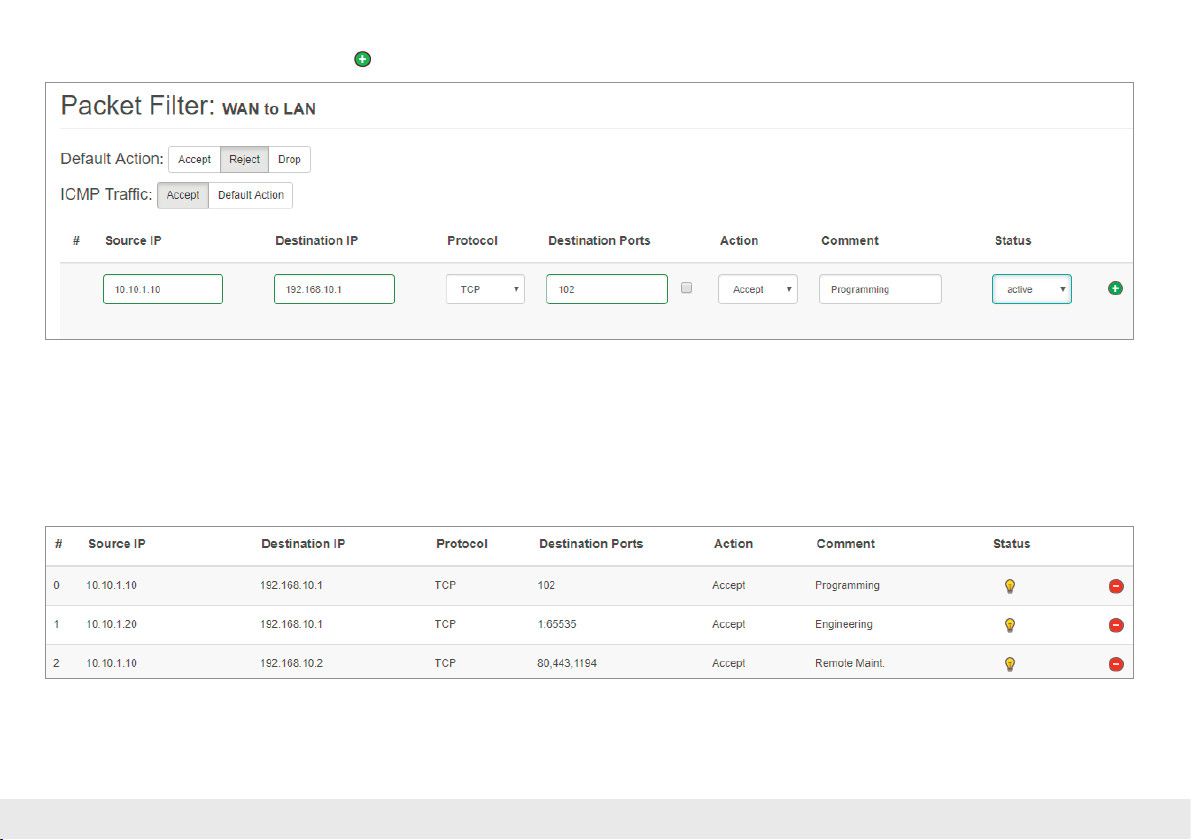
Now enter the following rule and save it with the button.
Source IP indicates the IP address of the active device in the production network (WAN). Destination IP the addressed device in the machine network (LAN).
The lter rules can be dened for one protocol type with protocol “TCP” or “UPD”.
Destination Ports indicates the ports to which the lter rules apply.
If a lter rule applies to several or even all ports, this can be simply dened in the “Destination Ports” eld. A list of ports is indicated separated by commas: “80,443,1194”.
A port range can be indicated with a colon: “4000:5000” or “1:65535” for all ports. Combinations of this are also possible: “80,443,4000:5000”.
Quick Start Guide WALL IE 11
Page 12
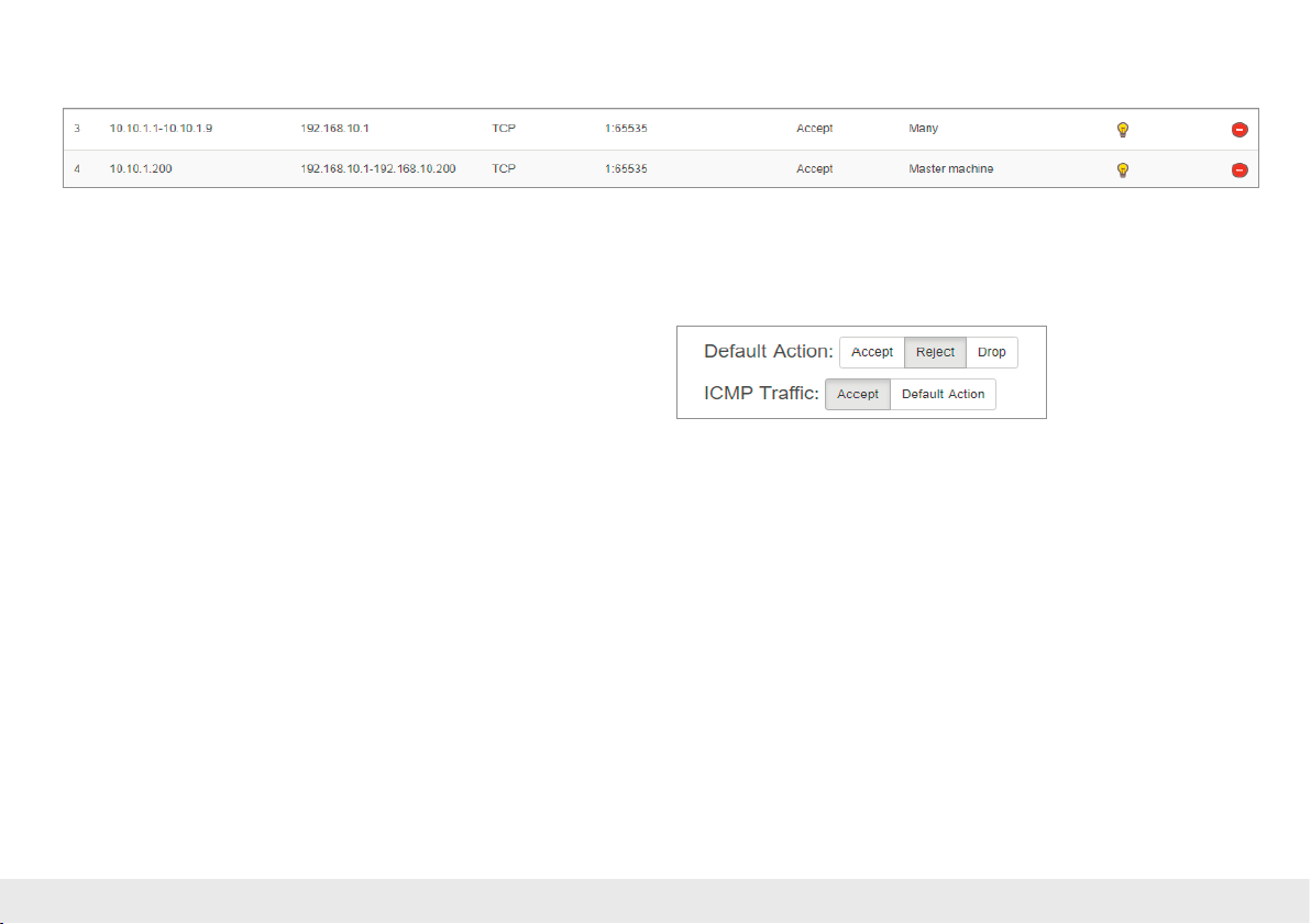
It is also possible to congure the access of several participants with one another. An IP range can be dened with a dash: “10.10.1.10-10.10.1.20“.
A list of IP addresses is indicated with commas: “10.10.1.10,10.10.1.15,10.10.1.20”.
Action denes whether this rule allows communication (“Accept”), rejects with error message (“Reject”), or simply rejects (“Drop”). The appropriate method here should
always be chosen in interaction with the “Default Action”. If the Default Action is, for example, “Reject” or “Drop”, the lter rules should all be set to “Accept” (Whitelisting).
If the Default Action is “Accept”, a block can be dened in the lter rules with “Reject” or “Drop” for certain devices (Blacklisting).
With the “ICMP Trafc” option, you can generally allow (“Accept”) the directing
of ICMP packets, for example, a “Ping”, (“Accept”) or prohibit them dependent
upon the packet lters (“Default Action”). If, for example, the packet lters “Default
Action” are set to “Reject” or “Drop”, and ICMP Trafc to “Default Action”, then no
ICMP frames of any kind are allowed through.
Quick Start Guide WALL IE12
Page 13
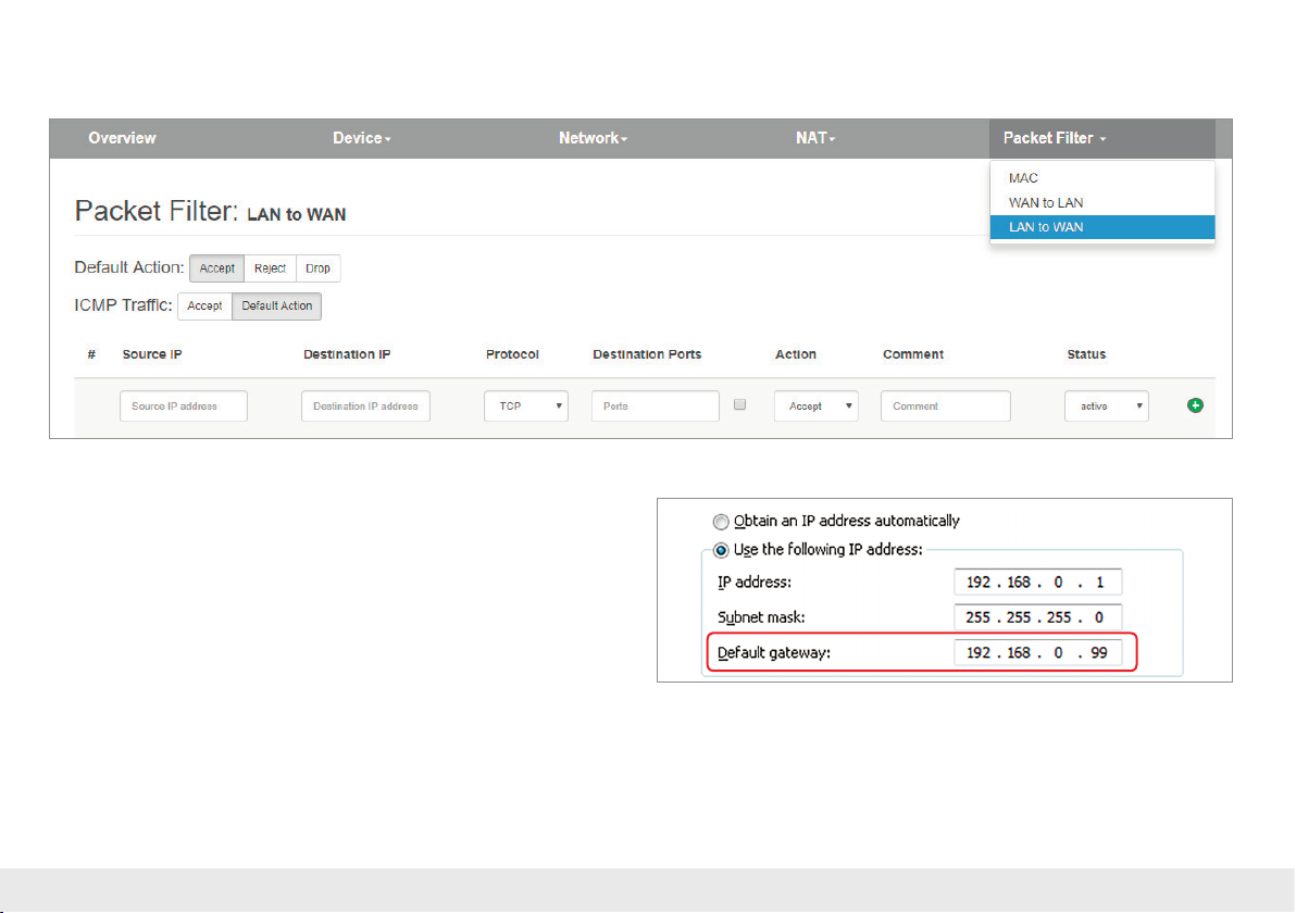
6.4. Packet lter “LAN to WAN”
In the basic state, data trafc is permitted for devices from the machine network (LAN) to the production network (WAN) without limitations (“Default Action”: “Accept”).
In the “LAN to WAN” packet lter, the communication of devices in LAN with devices
in the production network (WAN) or into the Internet is completely prohibited or is
blocked or allowed for particular devices.
The entry of the lter rules corresponds to the packet lters “WAN to LAN”, except that
the source IP is now the LAN IP and the destination IP addresses a device in the WAN.
Note: The MAC address ltering is also available in the NAT operating mode;
see page 21.
Quick Start Guide WALL IE 13
Page 14
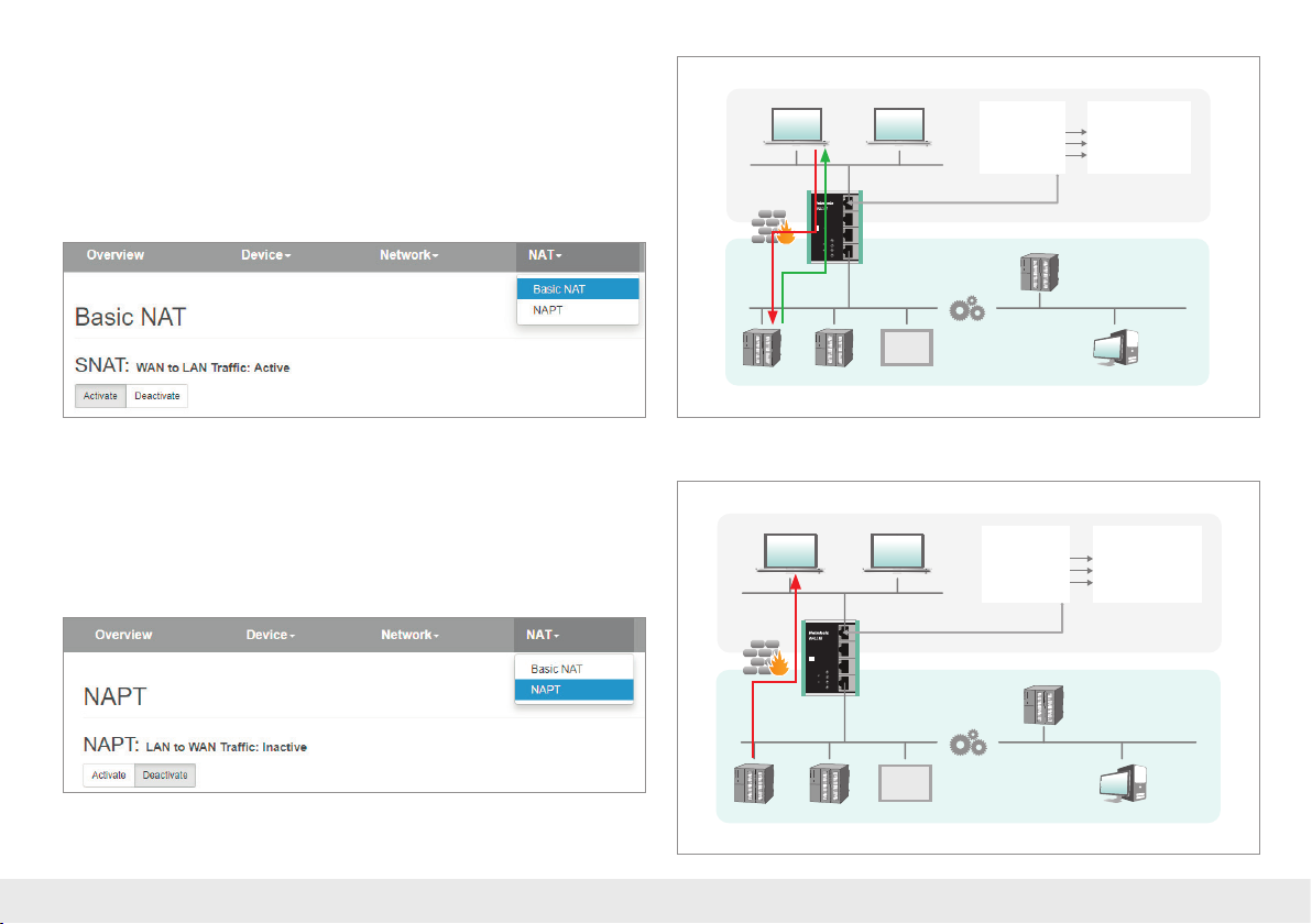
6.5. SNAT
The function “SNAT (Source NAT)” transparently forwards incoming trafc from the
WAN side to the LAN network. All data packets sent to the LAN are sent to the IP address
of the WALL IE.
Therefore, none of the LAN participants needs the WALLIE LAN-IP as „gateway“. This is
a considerable advantage when integrating into existing network structures, since the
parameters no longer have to be changed here.
10.10.1.10 10.10.1.20
10.10.1.1
External (WAN)
SN:
000000000
P3 LAN
PWR
FCN
RDY
P4 LANP1 WAN P2 LAN
RST
ACT
Ext. V DC
USR
Internal (LAN)
18 ... 30 V
+FEIN1IN2–
192.168.10.200
Company network
10.10.1.1:80
10.10.1.1:102
10.10.1.1:81
192.168.10.5
0
0
0
1
1
1
2
2
2
3
3
3
4
4
4
5
5
5
6
6
6
7
7
7
0
0
1
1
2
2
3
3
4
4
5
5
6
6
7
7
10.10.1.0/24
Internal IP & PortExternal Port
192.168.10.1:80
192.168.10.2:102
192.168.10.5:80
6.6. NAPT
“NAPT for LAN to WAN trafc” replaces the sender addresses of queries from the
automation cell (LAN) with the address of the WALL IE (“Source NAT”) in the WAN.
If the option is deactivated, the query packets are forwarded to the WAN with their
original sender IPs.
0
0
1
1
2
2
3
3
4
4
5
5
6
6
7
7
0
1
2
3
4
5
6
7
192.168.10.1 192.168.10.2 192.168.10.50 192.168.10.100
0
0
0
1
2
3
4
5
6
7
0
1
2
3
4
5
6
7
0
1
1
1
2
2
2
3
3
3
4
4
4
5
5
5
6
6
6
7
7
7
0
0
1
1
2
2
3
3
4
4
5
5
6
6
7
7
Machine network192.168.10.0/24
0
1
2
3
4
5
6
7
0
1
2
3
4
5
6
7
10.10.1.0/24
Internal IP & PortExternal Port
192.168.10.1:80
192.168.10.2:102
192.168.10.5:80
10.10.1.10 10.10.1.20
Company network
10.10.1.1:80
10.10.1.1:102
10.10.1.1:81
10.10.1.1
External (WAN)
SN:
000000000
P3 LAN
PWR
FCN
RDY
P4 LANP1 WAN P2 LAN
RST
ACT
Ext. V DC
USR
Internal (LAN)
18 ... 30 V
+FEIN1IN2–
192.168.10.200
0
0
1
1
2
2
3
3
4
4
5
5
6
6
7
7
0
1
2
3
4
5
6
7
192.168.10.1 192.168.10.2 192.168.10.50 192.168.10.100
0
0
1
2
3
4
5
6
7
0
1
2
3
4
5
6
7
0
0
1
1
1
2
2
2
3
3
3
4
4
4
5
5
5
6
6
6
7
7
7
0
0
1
1
2
2
3
3
4
4
5
5
6
6
7
7
192.168.10.5
0
0
1
1
2
2
3
3
4
4
5
5
6
6
7
7
0
1
2
3
4
5
6
7
Machine network192.168.10.0/24
Quick Start Guide WALL IE14
Page 15
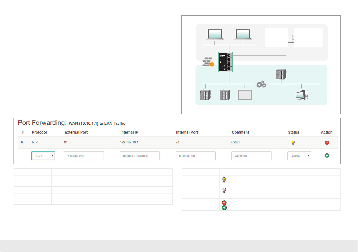
6.7. Port forwarding
With the help of port forwarding (“Port forwarding for WAN to LAN trafc”), it can
be congured that packets at a certain TCP/UDP port of the WALL IE (WAN) can
be forwarded to a participant in the automation cell (LAN) (e.g. 10.10.1.1:81 to
192.168.10.5:80).
10.10.1.10 10.10.1.20
Company network
10.10.1.1:80
10.10.1.1:102
10.10.1.1:81
10.10.1.0/24
Internal IP & PortExternal Port
192.168.10.1:80
192.168.10.2:102
192.168.10.5:80
Important: If with the packet lters “WAN to LAN” the default action is set to “Reject”
or “Drop”, the corresponding lter rules for access must also be created for each port
forwarding entry.
Protocol TCP/UDP
External port The port under which the frames in the WAN under the ad-
dress of the WALL IE are received.
Internal IP The IP address to be addressed in the machine network (LAN).
Internal port The port of the device to be addressed in the machine net-
work (LAN).
Note: “Port forwarding” and “Basic NAT” can be used simultaneously in the NAT
operating mode.
The MAC address ltering is also available in the NAT operating mode; see page 21.
10.10.1.1
External (WAN)
SN:
000000000
P3 LAN
PWR
FCN
RDY
P4 LANP1 WAN P2 LAN
RST
ACT
Ext. V DC
USR
Internal (LAN)
18 ... 30 V
+FEIN1IN2–
192.168.10.200
0
0
1
1
2
2
3
3
4
4
5
5
6
6
7
7
0
1
2
3
4
5
6
7
192.168.10.1 192.168.10.2 192.168.10.50 192.168.10.100
0
0
1
2
3
4
5
6
7
0
1
2
3
4
5
6
7
0
0
1
1
1
2
2
2
3
3
3
4
4
4
5
5
5
6
6
6
7
7
7
0
0
1
1
2
2
3
3
4
4
5
5
6
6
7
7
192.168.10.5
Machine network192.168.10.0/24
Comment Freely denable comment.
Status
Rule is active (a click on the lamp symbol changes the rule
status to inactive)
Rule is inactive (a click on the lamp symbol changes the
rule status to active)
Action
Deletes a rule.
Adds a rule.
0
0
0
1
1
1
2
2
2
3
3
3
4
4
4
5
5
5
6
6
6
7
7
7
0
0
1
1
2
2
3
3
4
4
5
5
6
6
7
7
Quick Start Guide WALL IE 15
Page 16
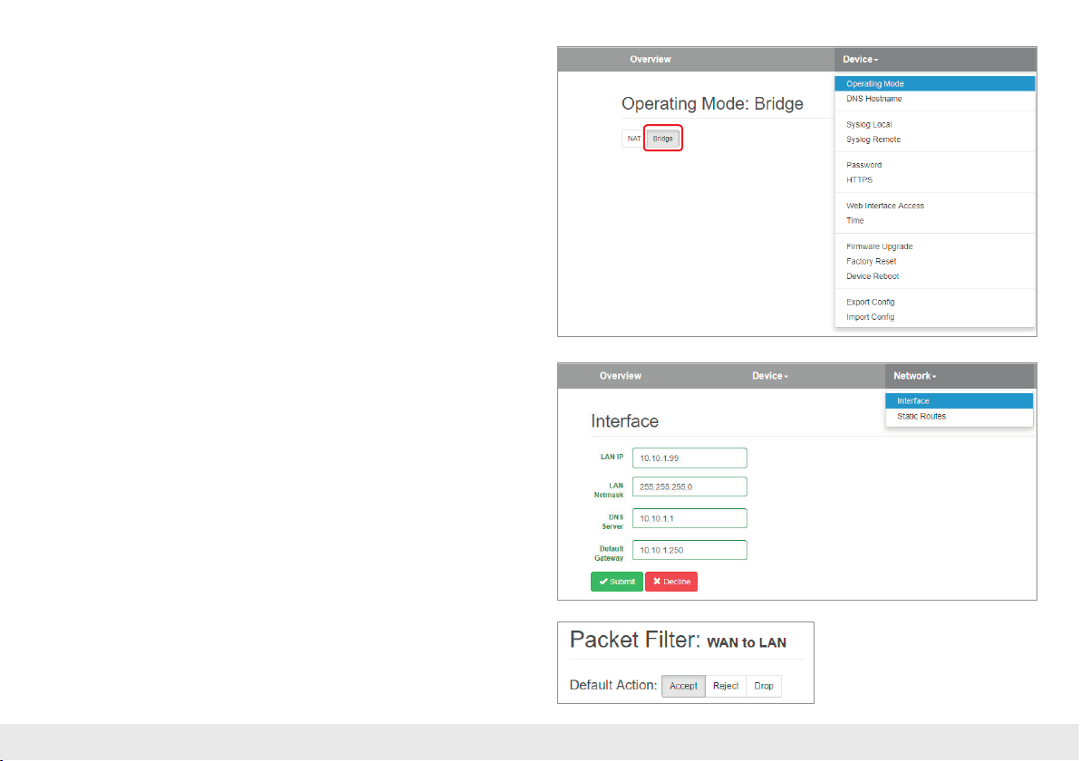
7. Bridge mode
To activate the Bridge operating mode, select the “Operating Mode” menu point in
the “Device” menu and set this to “Bridge”.
7. Adjustment of the IP addresses in the bridge operating mode
Click on the “Network” menu and select the sub-menu “Interface”. The IP addresses
of the WALL IE (“LAN IP”) and afliated subnet masks (“LAN netmask”) can be
dened here.
Note: In the bridge operating mode, the dened interface settings are also equally valid
at the WAN port of the WALL IE.
A DNS server and a default gateway can also be indicated.
This is necessary when devices from the LAN should reach the Internet via the WALL IE.
If these are not indicated, then communication of devices in the LAN with the Internet
is prevented.
The entry is saved with the “Submit” button.
Important: In the bridge mode, all ports are initially blocked for “WAN-to-LAN” data
transfer for security reasons!
In order to enable access, packet lter rules must be created or the “Default Action” for
the packet lters be set to “Accept”. See the following chapter.
Quick Start Guide WALL IE16
Page 17
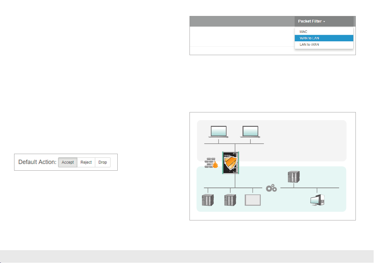
7.2. Packet lter “WAN to LAN”
The packet lters enable the limitation of access between the production network
(WAN) and the machine network (LAN).
For example, it can be congured that only certain participants from the production
network may exchange data with dened participants from the automation cell.
The following lter criteria on layers 3 and 4 are available: IPv4 addresses, protocol
(TCP/UDP), and ports.
Note: The packet lters are always also available in the direction “LAN to WAN”,
see page 20.
Select the “WAN to LAN” menu point in the “Packet Filter” menu.
With the “Default Option”, you can set whether all frames are generally allowed
(“Accept”) and only special packets are ltered (“Blacklisting”), or whether all frames
are generally prohibited (“Reject” / “Drop”) and only those frames are allowed to
pass through that correspond with the lter rules (“Whitelisting”).
If you initially don’t wish to lter, set the default action to “Accept”.
In order to limit access to the machine network to certain participants in the WAN,
set the default action to “Reject” or “Drop”. In the case of prohibited frames from the
WAN, “Reject” sends an error message in response, while “Drop” rejects the frame
without sending an error message.
Example: A PC in the production network (WAN) has the IP address 10.10.1.10
(e.g. a visualization). This PC should be able to access the CPU with the IP address
10.10.1.30 within the LAN via the por t 102 with the help of the TCP protocol.
Company network
10.10.1.0/24
10.10.1.10 10 .10.1.20
External (WAN)
SN:
000000000
P3 LAN
PWR
FCN
RDY
P4 LANP1 WAN P2 LAN
RST
ACT
Ext. V DC
USR
18 ... 30 V
0
0
0
1
1
1
2
2
2
3
3
3
4
4
4
5
5
5
6
6
6
7
7
7
0
0
1
1
2
2
3
3
4
4
5
5
6
6
7
7
10.10.1.30 10.10.1.31 10.1 0.1.50 10.10.1.100
Internal (LAN)
+FEIN1IN2–
0
0
0
1
1
1
2
2
2
3
3
3
4
4
4
5
5
5
6
6
6
7
7
7
0
0
1
1
2
2
3
3
4
4
5
5
6
6
7
7
10.10.1.32
0
1
2
3
4
5
6
7
0
0
1
1
2
2
3
3
4
4
5
5
6
6
7
7
0
0
1
1
2
2
3
3
4
4
5
5
6
6
7
7
Machine network10.10.1.0/24
Quick Start Guide WALL IE 17
Page 18
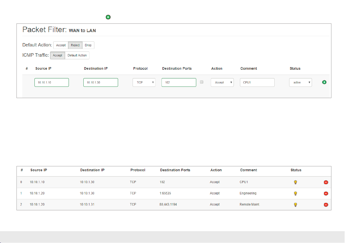
Now enter the following rule and save it with the button.
Source IP indicates the IP address of the active device in the production network (WAN).
Destination IP the addressed device in the machine network (LAN).
The lter rules can be dened for one protocol type with protocol “TCP” or “UPD”.
Destination Ports indicates the ports to which the lter rules apply.
If a lter rule applies to several or even all ports, this can be simply dened in the “Destination Ports” eld. A list of ports is indicated separated by commas: “80,443,1194”.
A port range can be indicated with a colon: “4000:5000” or “1:65535” for all ports. Combinations of this are also possible: “80,443,4000:5000”.
Quick Start Guide WALL IE18
Page 19
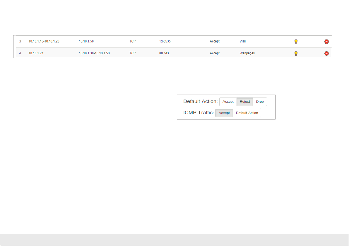
It is also possible to congure the access of several participants with one another. An IP range can be dened with a dash: “10.10.1.10-10.10.1.20“.
A list of IP addresses is indicated with commas: “10.10.1.10,10.10.1.15,10.10.1.20”.
Action denes whether this rule allows communication (“Accept”), rejects with error message (“Reject”), or simply rejects (“Drop”). The appropriate method here should
always be chosen in interaction with the “Default Action”. If the Default Action is, for example, “Reject” or “Drop”, the lter rules should all be set to “Accept” (Whitelisting).
If the Default Action is “Accept”, a block can be dened in the lter rules with “Reject” or “Drop” for certain devices (Blacklisting).
With the “ICMP Trafc” option, you can generally allow (“Accept”) the directing
of ICMP packets, for example, a “Ping”, (“Accept”) or prohibit them dependent
upon the packet lters (“Default Action”). If, for example, the packet lters “Default
Action” are set to “Reject” or “Drop”, and ICMP Trafc to “Default Action”, then no
ICMP frames of any kind are allowed through.
Quick Start Guide WALL IE 19
Page 20
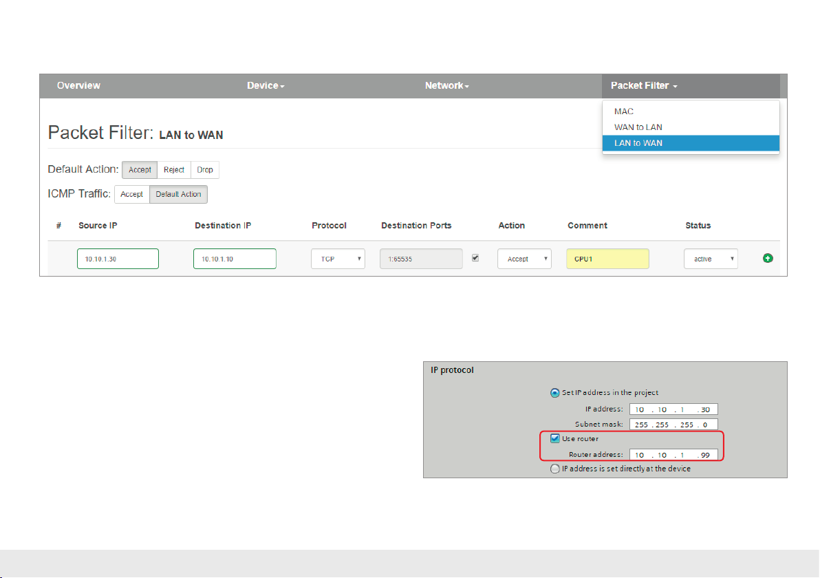
7.3. Packet lter “LAN to WAN”
In the basic state, data transfer is permitted for devices from the machine network (LAN) to the production network (WAN) without limitations (“Default Action”: “Accept”).
In the “LAN to WAN” packet lter, the communication of devices in LAN with devices
in the production network (WAN) can be completely prohibited or be blocked or
allowed for particular devices.
Note: The MAC address ltering is also available in the Bridge operating mode;
see page 21.
Important: In the event that devices in the LAN should communicate with devices in
the production network, the LAN IP address of the WALL IE must also be entered for the
devices in the LAN as a gateway.
Quick Start Guide WALL IE20
Page 21
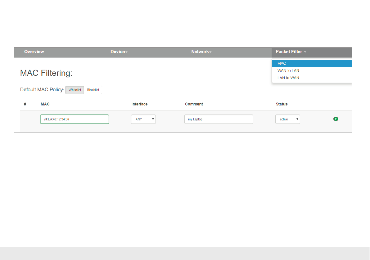
8. MAC address ltering
With the function “MAC Filtering;” communication via the WALL IE can be limited to devices with certain MAC addresses (“Whitelisting”) or devices with certain MAC
addresses can be denied access (“Blacklisting”).
Filtering for each MAC address can be activated separately on the WAN, on the LAN, or on both sides (“ANY”).
MAC addresses must always be entered in the format “AA:BB:CC:DD:EE:FF”, whereby
numbers are to be indicated with hexadecimals.
Important: MAC Filtering has the highest priority of all lters in the WALL IE. As soon as
the rst MAC address has been entered in the MAC lter mode “Whitelist”, only frames
from this MAC address are allowed to pass through, irrespective of all other packet lter
rules.
Quick Start Guide WALL IE 21
If MAC ltering is used in the “Whitelist” mode, the MAC addresses of all permitted
devices are indicated.
If no MAC lter rule has been entered or activated, the “MAC Filtering” is completely
deactivated, irrespective of the “Default MAC Policy”.
MAC ltering can be used both in the NAT and in the Bridge operating mode.
Note: In the NAT mode, the MAC ltering is only carried out WHEN the MAC address is
also indicated in the IP header of the packet. Layer 2 frames are not forwarded in the
NAT mode. The MAC ltering takes place on layer 2 in the bridge mode.
Page 22
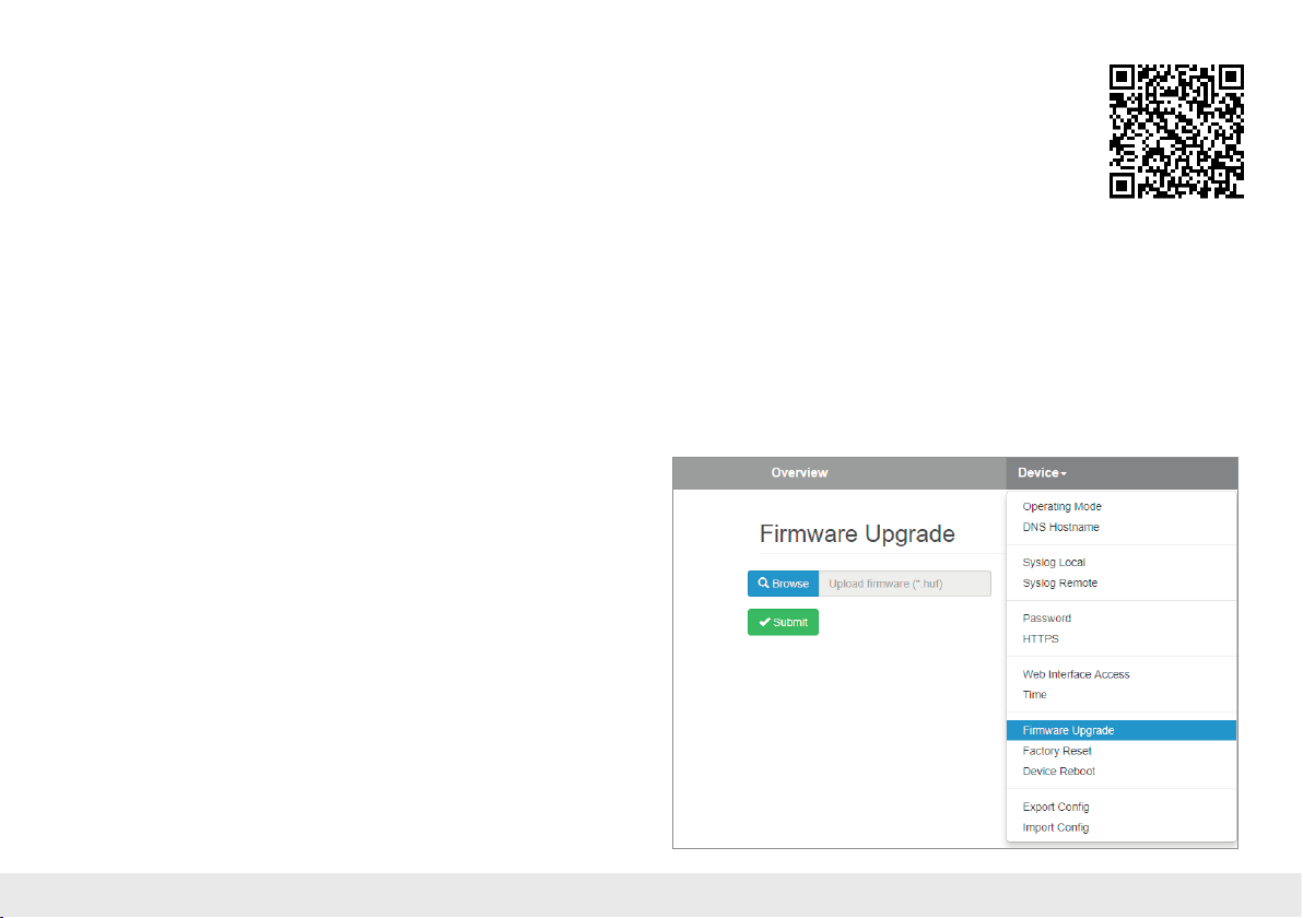
9. Firmware update
The rmware of the WALL IE can be very simply updated via the website. You receive
the rmware from the Helmholz website under www.helmholz.com or at Helmholz
Support ([email protected]).
Link to the current rmware:
https://www.helmholz.de/en/products/industrial-ethernet/nat-gateway-rewall/
wall-ie/#tab-software
The rmware le has the le ending “HUF” (Helmholz Update File) and is encoded
to protect it from being changed.
File the rmware le on your PC and select the storage location with “Browse”.
The rmware le is then transferred to the WALL IE. This can take up to 1 minute,
depending upon the network connection.
The rmware le is decoded and checked in the WALL IE. If the content is correct,
the rmware is burned into the program memory and a restart of the WALL IE takes
place.
Important: Operation of the WALL IE is interrupted during the update procedure.
Do not shut off the device during the update procedure.
Note: The conguration of the WALL IE is retained at a higher version following an
update, to the extent that this is technically possible. However, a “downgrade” to an
older rmware version can result in conguration errors. Carrying out a factory reset is
recommended following a downgrade.
Note: Following a rmware update, it may be necessary to delete the browser cache
once in order to update obsolete JavaScript elements of the WALL IE website.
Quick Start Guide WALL IE22
Page 23
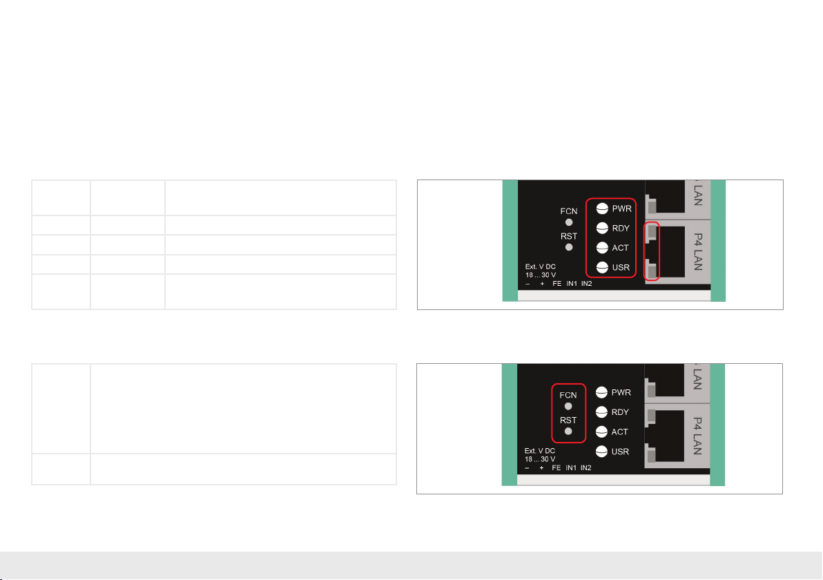
10. Resetting to factory settings
In order to reset WALL IE to the delivery status, the “FCN” button must be activated
while the device is restarted. A restart can be carried out with Power OFF/ON, by
activating the “RST” button or with the “Device reboot” function at the website.
The successful resetting of the parameters and settings is acknowledged during the
boot process by the lit “USR” LED.
11. LED status information
PWR Off
On
RDY On Device is ready to operate.
ACT Flashing or on Data transfer permitted between WAN and LAN.
USR On Factory settings reset active.
RJ45 LEDs Green (Link)
Orange (Act)
No power supply or device defective.
Device is correctly supplied with voltage.
Connected.
Data transfer at the port.
12. Button functions
FCN The WALL IE can be reset to factory settings with the “FCN” button.
To this purpose, the “FCN” button must be kept pressed during the
run-up phase of the WALL IE.
The successful resetting of the parameters and settings is acknowledged during the boot process by the lit “USR” LED.
The “FCN” button can then be released.
RST The “RST” button triggers an immediate restart of the WALL IE,
Quick Start Guide WALL IE 23
in the course of which all saved settings are retained.
Page 24

13. Technical data
WALL IE, Industrial Ethernet Bridge and Firewall 700-860-WAL01)
Dimensions (DxWxH) 35 x 59 x 76 mm
Weight Approx. 130 g
Number of inputs 2 | DC 24 V, as per DIN EN 61131-2 Type 2
WAN interface 1 x
- Type 10 Base-T/100 Base-T
- Connection RJ45 socket
- Transmission rate 10/100 Mbps
LAN interface 3 x
- Type 10 Base-T/100 Base-T
- Connection RJ45 socket
- Transmission rate 10/100 Mbps
Operating modes Bridge, NAT (Basic NAT, NAPT)
Packet lter
Status indicator
Voltage supply 24 V DC, 18–30 V DC
Current draw Max. 100 mA at 24 V DC
Power dissipation Max. 2.4 W
Ambient conditions
- Ambient temperature -40 °C ... +75°C
- Transport and storage tem-
perature
- Relative air humidity 95 % r H without condensation
- Pollution degree 2
- Protection rating IP20
Certications CE, UL
UL UL 61010-1/ UL 61010-2-201
IPV4 addresses, protocol (TCP/UDP), ports:
“WAN to LAN” and “LAN to WAN” separated,
MAC addresses (black & whitelisting)
4 LEDs, function status
8 LEDs, Ethernet status
-40 to +85°C
- Voltage supply
- Pollution degree 2
- Altitude Up to 2,000 m
- Temperature cable rating 87 °C
Note:
The contents of this Quick Start Guide have been checked by us so as to ensure that
they match the hardware and software described. However, as deviations cannot be
excluded, we can accept no responsibility for complete agreement.
The information in this Quick Start Guide is, however, updated on a regular basis.
When using your purchased products, please make sure to use the latest version
of this Quick Start Guide, which can be viewed and downloaded on the Internet from
www.helmholz.com. Our customers are at the center of everything we do.
We welcome all ideas and suggestions.
DC 24 V (18 ... 30 V DC, SELV and limited
energy circuit)
Helmholz GmbH & Co. KG | Hannberger Weg 2 | 91091 Großenseebach | Germany | Phone +49 9135 7380-0 | Fax +49 9135 7380-110 | [email protected] | www.helmholz.com
 Loading...