

Page 1
Systeme Helmholz GmbH z Hannberger Weg 2 z D-91091 Großenseebach
Phone: +49 9135 7380-0
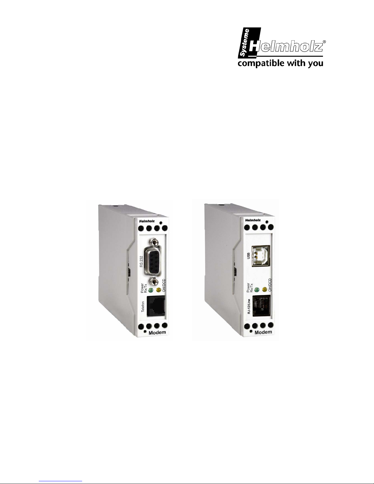
56-k Modem „small“/
56-k Modem USB„small“
700-751-HSM21 / 700-751-HSM31
Operating Manual
Version: 2.0 / 03.07
Manual Order number : 900-751-HSM21/en
Page 2

Helmholz Modem 56k small/Modem 56k USB small 2
All rights are reserved, including those of translation, reprinting,
and reproduction of this manual, or parts thereof. No part of this
manual may be reproduced, processed, copied, or transmitted in
any way whatsoever (photocopy, microfilm, or other method)
without the express written permission of Systeme Helmholz
GmbH, not even for use as training material, or using electronic
systems. All rights reserved in the case of a patent grant or registration of a utility model or design.
Copyright © 2009 by
Systeme Helmholz GmbH
Hannberger Weg 2, 91091 Großenseebach, Germany
Note:
We have checked the content of this manual for conformity with
the hardware and software described. Nevertheless, because deviations cannot be ruled out, we cannot accept any liability for
complete conformity. The information in this manual is regularly
updated. When using purchased products, please heed the latest
version of the manual, which can be viewed in the Internet at
www.helmholz.de, from where it can also be downloaded.
Our customers are important to us. We are always glad to receive
suggestions for improvement and ideas.
Step and SIMATIC are registered trademarks of SIEMENS
Page 3

Contents
Helmholz Modem 56k small/Modem 56k USB small 3
1 SCOPE OF DELIVERY .................................................................................... 6
2 FUNCTION OVERVIEW ................................................................................. 6
3 NOTES REGARDING THE USE OF THE MANUAL......................................... 7
4 INITIAL OPERATION..................................................................................... 8
4.1 FRONT PANEL .................................................................................................. 8
4.2 TOP ................................................................................................................ 9
4.3 USER PROFILES................................................................................................. 9
4.4 INSTALLATION ............................................................................................... 10
4.5 INSTALLATION OF A USB DRIVER ..................................................................... 12
5 FUNCTIONS................................................................................................ 18
5.1 CONFIGURATION ........................................................................................... 18
5.2 SERIAL DATA TRANSMISSION ........................................................................... 20
5.3 ERROR CORRECTION ....................................................................................... 24
5.4 DATA COMPRESSION....................................................................................... 24
5.5 SELECTIVE CALL ANSWER ............................................................................... 26
5.6 SEND MESSAGES............................................................................................. 28
5.7 REMOTE CONFIGURATION (REMOTE CONTROL)................................................ 30
5.8 ACCESS CONTROL.......................................................................................... 32
5.9 DATA TRANSMIT CONTROLLER (IDLE CONNECTION CONTROL) .......................... 34
5.10 PRIORITY CIRCUIT FOR MODEMS WITH PHONES CONNECTED IN SERIES ............... 35
6 CONFIGURATION SOFTWARE HSCOMM .................................................. 38
Page 4

Contents
Helmholz Modem 56k small/Modem 56k USB small 4
7 OPERATION WITH A PLC ........................................................................... 39
8 FIRMWARE UPDATE ................................................................................... 40
8.1 FLASHCOM.EXE.............................................................................................. 40
8.2 TERMINAL PROGRAM...................................................................................... 41
9 AT COMMAND SET .................................................................................... 42
9.1 OVERVIEW AT COMMANDS ............................................................................ 43
9.2 OVERVIEW FAX AND VOICE COMMANDS.......................................................... 67
9.3 AT MESSAGES................................................................................................ 67
10 S REGISTRY................................................................................................. 71
10.1 OVERVIEW S REGISTRY ................................................................................... 71
10.2 DESCRIPTION S REGISTRY................................................................................ 72
11 SENDING SMS AS FAX OR E-MAIL ............................................................ 81
11.1 SMS AS FAX .................................................................................................. 81
11.2 SMS AS E-MAIL .............................................................................................. 82
12 FAQ ............................................................................................................. 83
13 SAFETY INSTRUCTIONS ............................................................................. 85
13.1 GENERAL ...................................................................................................... 85
13.2 CLEANING..................................................................................................... 85
14 TECHNICAL DATA ...................................................................................... 86
14.1 MECHANICAL FEATURES ................................................................................. 86
14.2 POWER SUPPLY .............................................................................................. 86
14.3 PC INTERFACE ............................................................................................... 87
Page 5

Contents
Helmholz Modem 56k small/Modem 56k USB small 5
14.4 POSSIBLE INTERFACE SPEEDS............................................................................ 88
14.5 SUPPORTED TRANSMISSION STANDARDS ........................................................... 89
14.6 TELEPHONE INTERFACE ................................................................................... 89
14.7 ITU STANDARDS (CCITT) .............................................................................. 91
15 COUNTRY CODES ...................................................................................... 92
Page 6

6 Helmholz Modem 56k small/Modem 56k USB small
1 Scope of Delivery
Before you begin with the initial operation, please check if all accessories are
included in the box.
¾ HELMHOLZ Modem 56k small or
HELMHOLZ Modem 56k USB small
¾ 2 phone cords (TAE N at RJ12 and RJ12 at RJ12)
¾ PC connection cable
9/9-pin (RS232 cable) or USB connection cable
¾ User Guide
¾ CD-ROM (optional)
Please contact your supplier if the content is not complete. Please also check the modem for shipping damage. Please also refer to your supplier if anything is damaged.
Please keep the packaging material for possible future shipping or storage.
2 Function Overview
The HELMHOLZ Modem 56k small is a modem for the analogue telephone network. It
has a very compact design and very robust plastic housing. The modem supports the
following functions, which are described in detail in Chapter 5:
¾ Usage in 87 countries
¾ Establishing a data connection
¾ Auto answer
¾ Data flow control
¾ Error correction
¾ Data compression
¾ Idle connection control
¾ Firmware Update
¾ Remote configuration
¾ Security callback
Page 7

Helmholz Modem 56k small/Modem 56k USB small 7
3 Notes Regarding the Use of the Manual
¾ This manual uses the symbol for especially important notes. Further notes
will be marked accordingly.
¾ All factory settings are marked “default”.
Example (Chap. 5.7.3):
Enter old password (default: QWERTY)
¾ In Chapters 4 to 6 the description consists of two columns. Individual func-
tions are described on the left side. The according AT commands and the
modem responses can be found in the right column.
Function description AT command
Example (Chap. 5.2.7):
After the hardware reset, load the user profile 1 ATZ1
¾ All AT commands start with the letters AT and end with a “Return” (Carriage
Return - CR). AT commands can be entered in capital or small letters. The
command is evaluated as soon as the modem received a response.
¾ In the following, the used syntax is explained:
c ATDT AT command (font: Courier, bold)
d <Expression> Input of a parameter (font: Courier, bold)
e <Expression> Input of an optional parameter
(Font: Courier, bold)
f Expression Response from the modem (font: italic)
Examples:
c ATDT<n> Dialing of the phone number <n>
ATDT1234 Dialing of the phone number 1234
d+e AT+MS=<Modulation>, [Automode] Selection of the modulation
type
AT+MS=V92 Selection of the modulation
type V.92
AT+MS=V92,1 Selection of the modulation
typeV.92 with automatic
adjustment
f Connect The connection to the remote terminal is established
> Input prompt during the remote configuration.
Page 8
8 Helmholz Modem 56k small/Modem 56k USB small
4 Initial Operation
4.1 Front panel
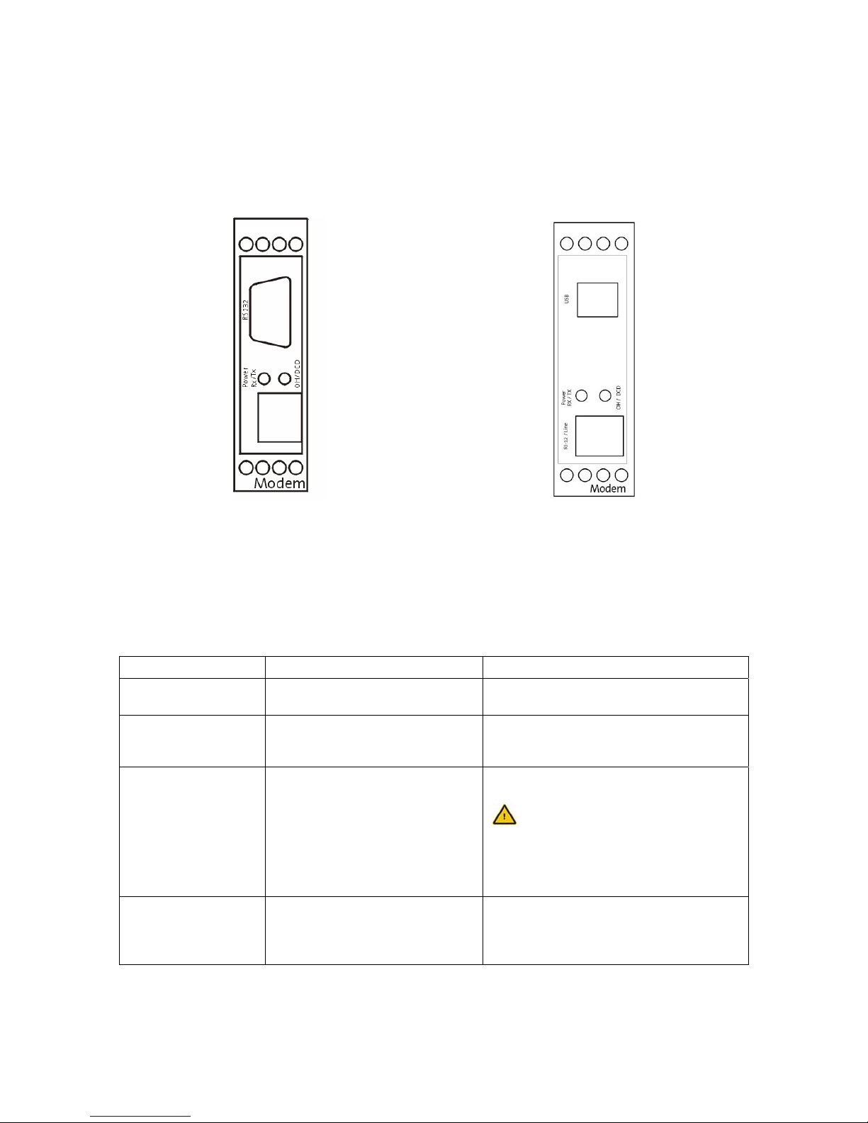
HELMHOLZ Modem 56k small HELMHOLZ Modem 56k USB small
The HELMHOLZ Modem 56k small INT has two LEDs to indicate the operating state:
The left LED (Power RX/TX) displays the condition of the operating voltage and a data
transmission. The right LED (OH/DCD) displays the status OH (off hook) and DCD (data carrier detect). The exact meaning of the display elements is described in the following table.
State Left LED Right LED
LED off No operating voltage applied. The modem is not “off hook” (it has not
yet “lifted the receiver”).
LED is green Operating voltage applied. The modem is hooked to the phone line
(it has “lifted the receiver”); a connections has not yet been established.
LED is or blinks orange
Data is transmitted. The connection to the remote terminal
is established, the carrier was detected
If the DCD line at the modem is
permanently switched on, it cannot
be distinguished, whether a connection to the remote terminal is active
or not.
LED is red The modem is not “off hook” (it has not
“lifted the receiver” yet) and the DCD
line at the modem is permanently
switched on.
Systeme Helmholz
Systeme Helmholz
Page 9

Helmholz Modem 56k small/Modem 56k USB small 9
4.2 Top
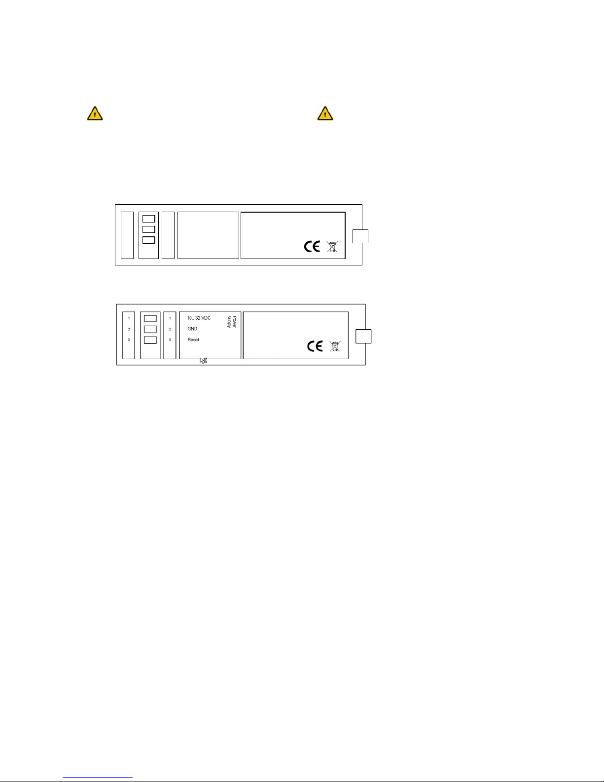
Terminal Meaning
1 10..32V
DC
Power supply 10V - 32V DC
2 GND Ground
3 Reset Reset input
INSYS MICROELECTRONICS GmbH
Internet: www.insys-tec .de
Sales: insys@insys-tec.de
Support: support@insys-tec.de
GND
Reset
10...32 VDC
Power
supply
1
2
3
1
2
3
4 N/A
4.3 User Profiles
The modem offers a choice of profiles:
¾ Default factory setting:
The default factory settings enable you to achieve a fixed defined
basic state of the modem. Starting with this “basis”, you can customize the modem according to your requirements.
¾ User profiles 0 and 1:
You can save configurations in the user profile, which may be reused for certain purposes.
A part of the S registry is saved in each profile. In the description, the affected registries are marked with an “*” in the S registry.
Systeme Helmholz GmbH
Internet:
www.helmholz.de
Sales:
Support: [email protected]
Page 10
10 Helmholz Modem 56k small/Modem 56k USB small
4.4 Installation
Please observe our safety instructions.
1. Mounting on DIN rail
2. Connecting the power supply
a) Connecting the ground connection
b) Connecting the power supply 10…32V DC
INSYS MICROELECTRONICS GmbH
Internet: www.insy s-te c.de
Sales: i nsys@insys-tec.de
Support: support@insys-tec .de
GND
Reset
10...32 VDC
Power
supply
1
2
3
1
2
3
HELMHOLZ Modem 56k small
HELMHOLZ Modem 56k USB small
Note: The minimum value is 10V DC.
The maximum value is 32V DC.
3. Switch on power supply
4. Connection with a PC
Connect the 9-pin jack at the modem with the serial interface or a
USB interface of your computer.
5. Installation of a driver
For HELMHOLZ Modem 56k small:
The installation of a driver is not required when using a terminal
program or the HSComm. If you use another application, a driver
may be necessary. Please find our current drivers at
http://www.helmholz.de/ or install the standard modem 336 under Windows.
For HELMHOLZ Modem 56k USB small:
If the HELMHOLZ USB drivers are not installed on your system
yet, you must perform the installation described in Chapter
4.5 .
6. Communication with the Modem
Now, start your communication program on the PC and set it to
the used COM interface. The modem will automatically adjust to
the baud rate of your PC.
7. Communication Control via a Terminal Program
Perform a short test using your terminal program.
Power LED lights
up green
Systeme Helmholz GmbH
Internet: www.helmholz.de
Sales:
Support: [email protected]
Helmholz Modem 56k USB small
Systeme Helmholz GmbH
Internet:
www.helmholz.de
Sales:
Support: [email protected]
Page 11

Helmholz Modem 56k small/Modem 56k USB small 11
(TeraTermPro, ProcommPlus).
Open the terminal program and enter
the command.
When the message appears on your monitor, the device has been
successfully installed.
8. Check the communication using the configuration program
HSComm
Open installed HSComm The configuration program will automatically search for the connected modem
9. Connection to the telephone network
Connect the modem with the phone outlet, using the supplied
phone cord.
10. Connection Test
Perform a manual connection, either to another modem or, in
this example, to Freenet.
Dial the following number 0101901929
For PBXs that require a code number to establish
a connection - usually “0”- a different command
must be used.
The modem will establish a connection
AT Enter
LED RXTX lights
up for a short
time
OK
ATDT 0101901929
ATX3DT 0,0101901929
LED OH lights up
Connect…
Page 12
12 Helmholz Modem 56k small/Modem 56k USB small
4.5 Installation of a USB Driver
(Only for HELMHOLZ Modem 56k USB small)
The installation of the HELMHOLZ modem 56k USB small is performed in three steps. During the first two installation steps, a virtual COM port is installed, through which a modem
can be addressed via a terminal program or the configuration software HSComm.
During the third step, a modem driver can be installed, which can address the HELMHOLZ
Modem 56 k USB small at the just installed COM port.
The following describes the installation of the driver using the operating system Windows
XP. The installation of the driver using Windows 2000 is slightly different, but in general
very similar.
Note: The installation of the driver files creates a
virtual serial interface (COM port) on the computer. The PC will treat this interface like a "real"
serial interface. All commands and functions in
this manual which relate to serial interfaces can
also be used for the version HELMHOLZ Modem
56k USB small.
4.5.1 COM port installation
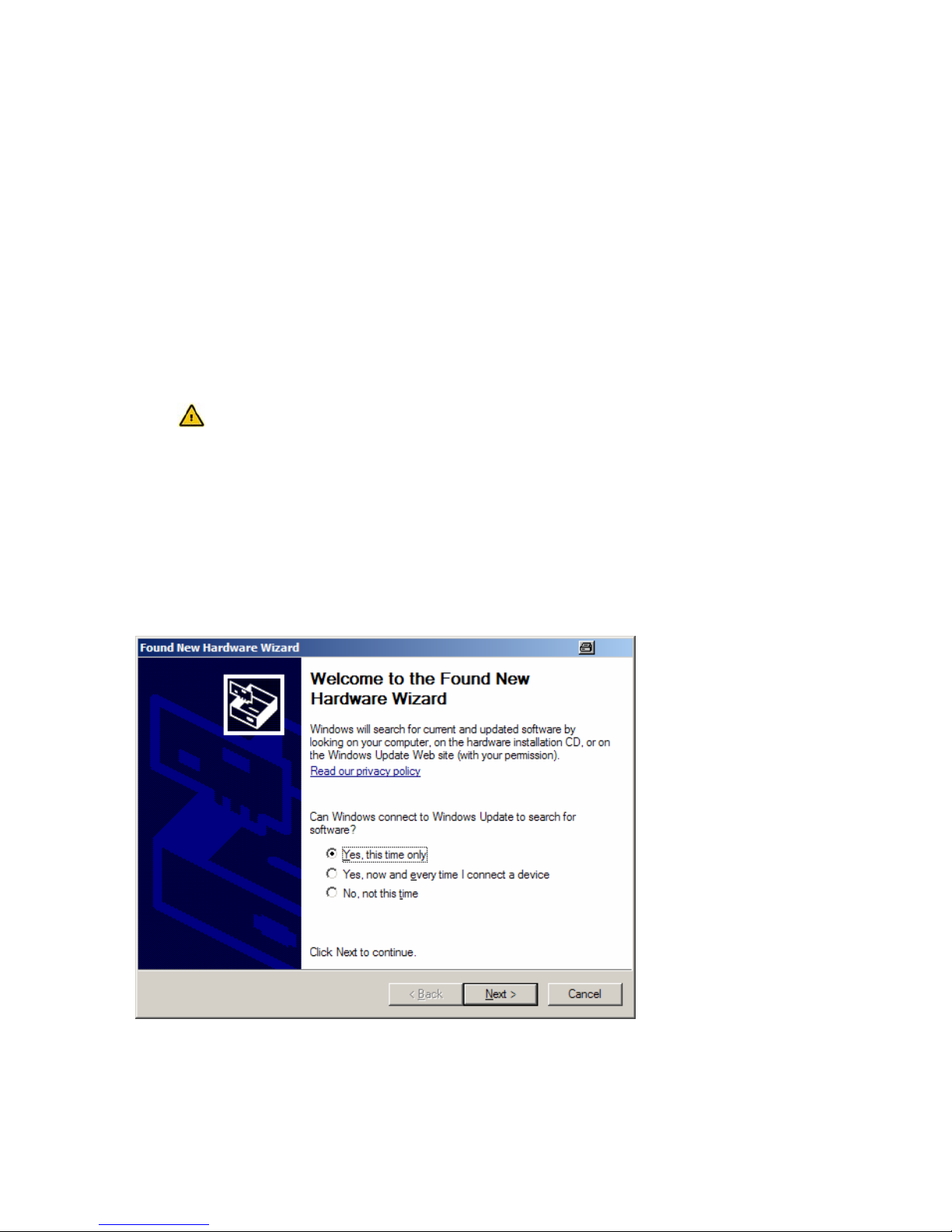
When connecting the modem, the following dialog is displayed:
Click on "Next"...
Page 13
Helmholz Modem 56k small/Modem 56k USB small 13
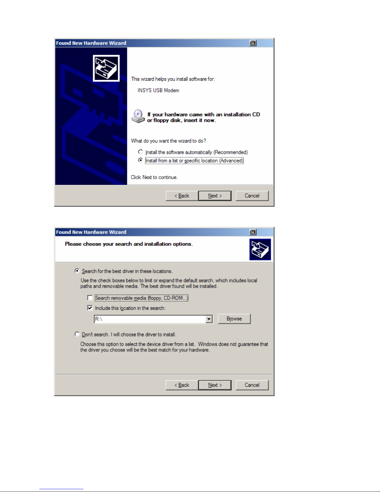
Select the item "Software from a list..." and click on "Next"...
Click the button "Browse" and enter the path to the location of the driver information.
E.g.: <CD Drive>\Driver\small_USB
The system will now search for the driver information.
Confirm any warning message from Windows XP by clicking the button "Continue installa-
tion".
Page 14
14 Helmholz Modem 56k small/Modem 56k USB small
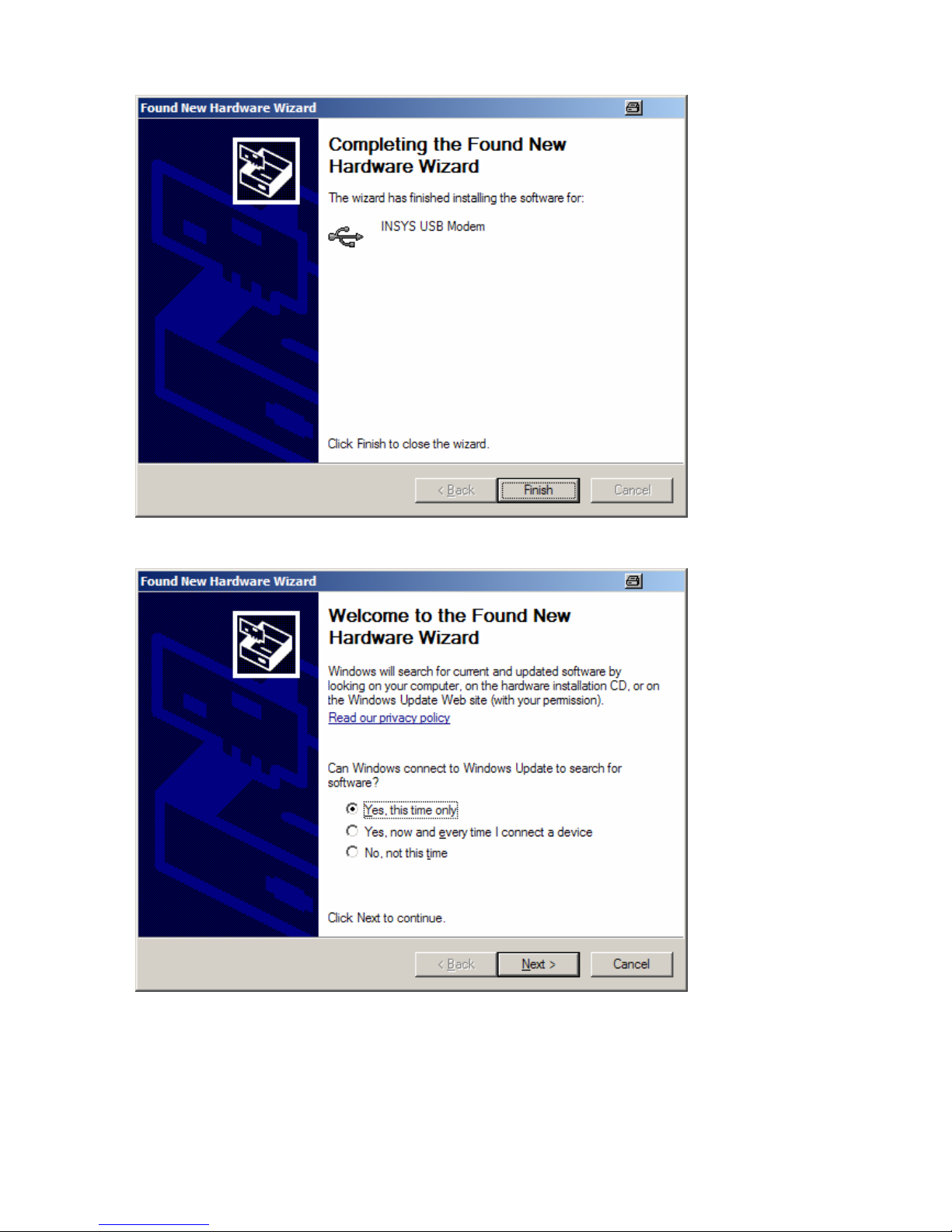
Click on "Finish" to complete the first part of the installation.
Note:
Immediately after the first driver has been installed, this installation route must be performed the same way a second time to install the second part of the driver.
Page 15
Helmholz Modem 56k small/Modem 56k USB small 15
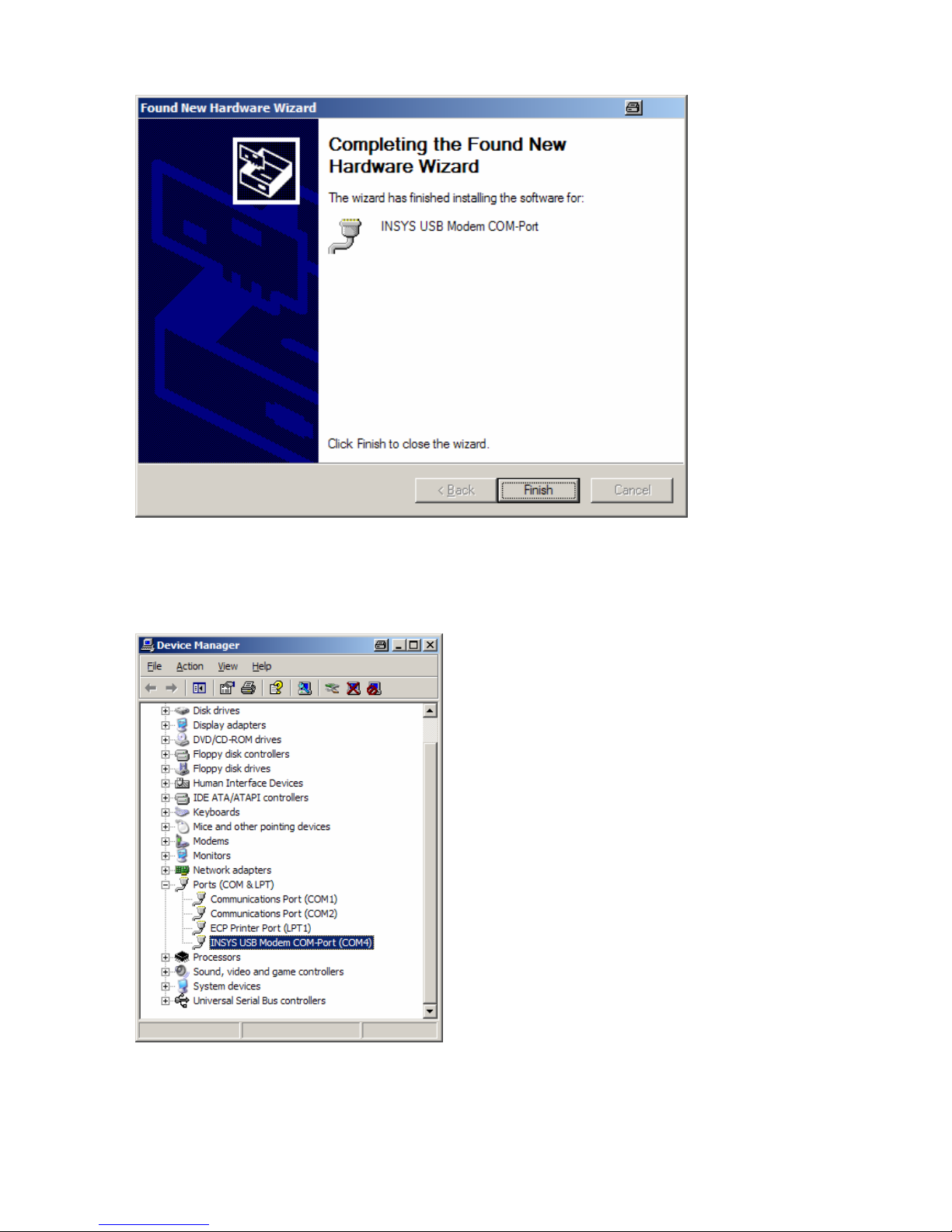
After the second installation has been completed, the system has a new COM port available.
You can check the installation by opening the device manager in the start menu at
Control Panel ->System -> Hardware -> Device Manager
In this example, the modem was installed at COM
port 4. The modem can now only be addressed via
this COM port, using the configuration software
HSComm, for example.
For many applications, the installation up to this
point is sufficient.
If the modem is supposed to appear as a modem in
the control panel as well (e.g. to setup a RDT - remote data transmission - connection), you must
install an additional modem driver to ensure the
functioning of the installed COM port. The following Chapter will show the details.
Page 16
16 Helmholz Modem 56k small/Modem 56k USB small
4.5.2 Modem Driver Installation
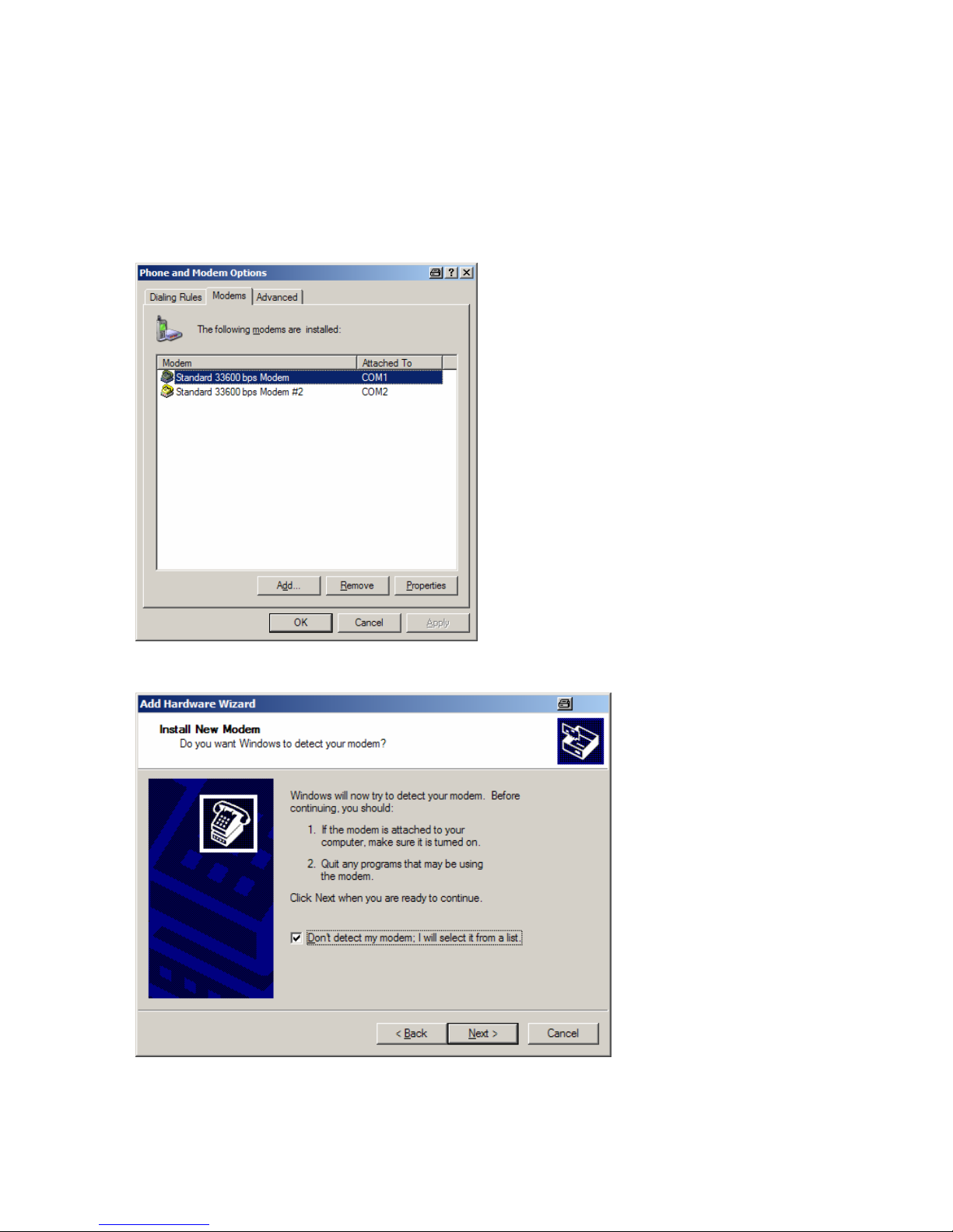
The following describes the installation of a driver for an HELMHOLZ Modem. Open the
modem management in the control panel.
Start menu:
Control Panel ->Network and Internet Connections -> Phone and Modem Options
Start the installation using the button "Add".
After activating the check box "Select Modem", click on the button "Next".
Page 17
Helmholz Modem 56k small/Modem 56k USB small 17
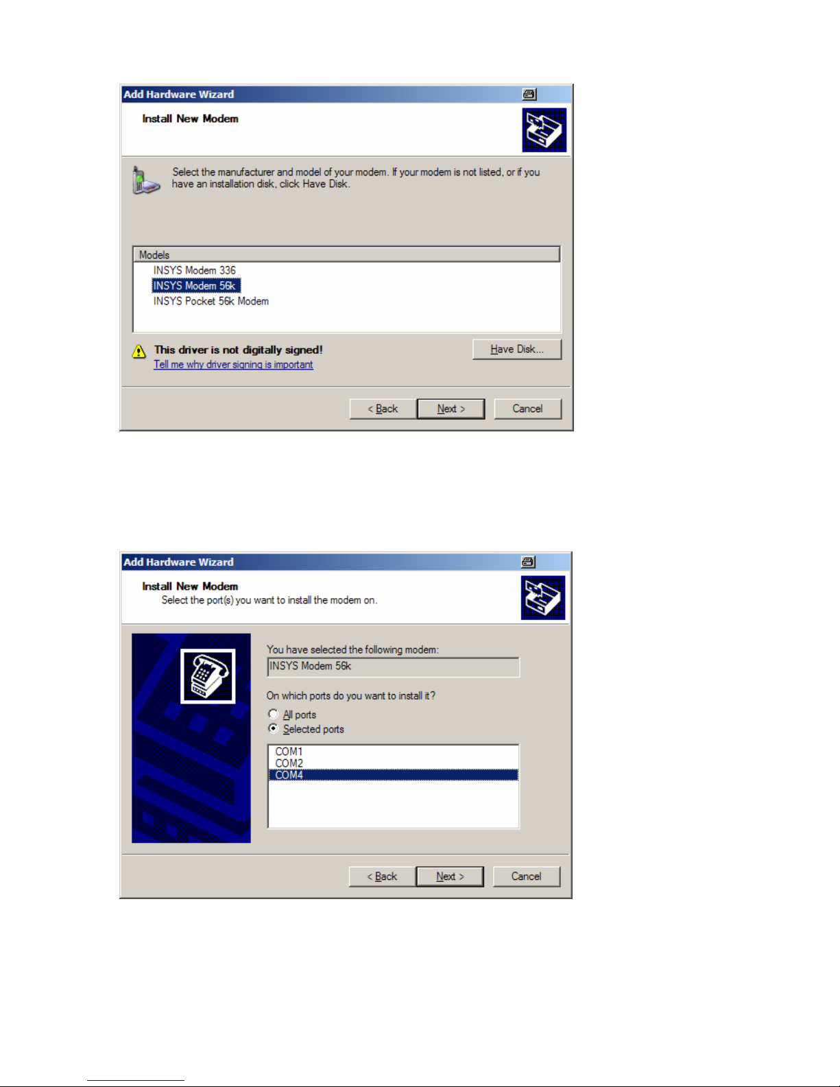
You can now either install a standard modem 56k or a special HELMHOLZ modem driver. If
necessary, you may need to enter the storage location manually using the button "Disk
Drive" to select the storage location.
E.g. at: <CD Drive>\DIN_Rail\Driver\Modem
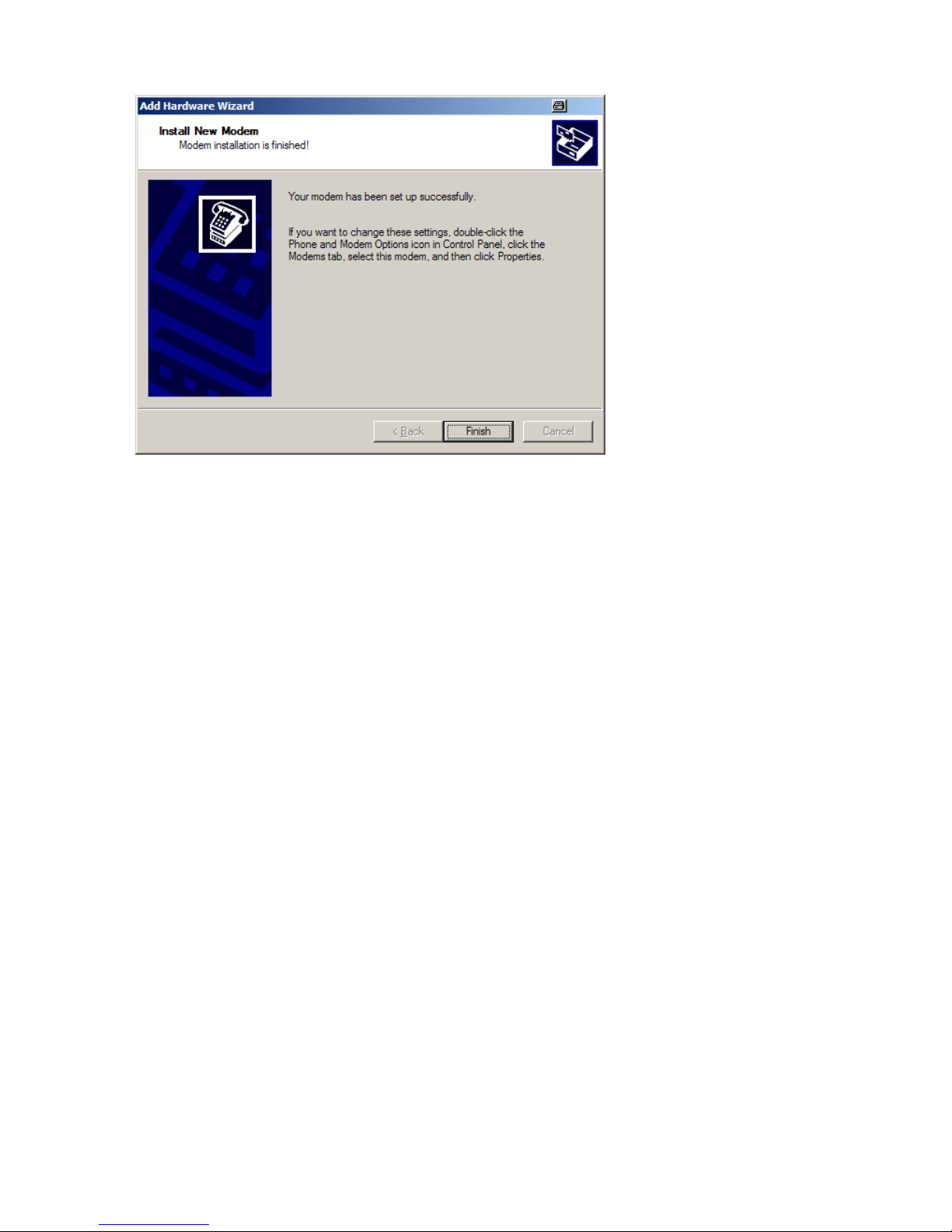
Now enter the COM port for the modem connection. Use the virtual COM port that was installed in the previous chapter. In our example, this is COM 4.
Click on "Next" to complete the installation.
Page 18
18 Helmholz Modem 56k small/Modem 56k USB small
The installation is completed.
5 Functions
5.1 Configuration
5.1.1 Configuration Change
Loading the factory settings into the active profile will enable you
to easily recover an executable state.
Loading the user profile 0
Loading the user profile 1
Prior to the loading of the user profile, a reset is performed.
The settings of all profiles can be displayed in a chart.
AT&F
ATZ0 ATZ
ATZ1
AT&
V
Page 19

Helmholz Modem 56k small/Modem 56k USB small 19
Example:
The active profile will show all settings currently used by the modem.
ACTIVE PROFILE:
B3 E1 L1 M1 Q0 T V1 W0 X4 *A1 *L0 *M0 *P0 *R1 %B0 %C3 %E2 %S0
\A1 \N3 \V0 &A0 &C1 &D2 &G0 &K3 &Q5 &R1 &S0 &X0 &Y0
S00:005 S02:043 S06:003 S07:050 S08:002 S09:006 S10:014 S11:085
S12:050 S13:003
S15:000 S17:042 S18:000 S24:000 S36:135 S40:104 S41:195 S46:138
S95:000
Our example currently shows the settings from user profile 0.
User profile 0:
STORED PROFILE 0:
B3 E1 L1 M1 Q0 T V1 W0 X4 *A1 *L0 *M0 *P0 *R1 %B0 %C3 %E2 %S0
\A1 \N3 \V0 &A0 &C1 &D2 &G0 &K3 &Q5 &R1 &S0 &X0
S00:005 S02:043 S06:003 S07:050 S08:002 S09:006 S10:014 S11:085
S12:050 S13:003
S15:000 S17:042 S18:000 S24:000 S36:135 S40:104 S41:195 S46:138
S95:000
User profile 1:
STORED PROFILE 1:
B3 E1 L1 M1 Q0 T V1 W0 X4 *A1 *L0 *M0 *P0 *R1 %B0 %C3 %E2 %S0
\A1 \N3 \V0 &A0 &C1 &D2 &G0 &K3 &Q5 &R1 &S0 &X0
S00:005 S02:043 S06:003 S07:050 S08:002 S09:006 S10:014 S11:085
S12:050 S13:003
S15:000 S17:042 S18:000 S24:000 S36:135 S40:104 S41:195 S46:138
S95:000
Note: The user profiles 0 and 1 can be modified without affecting the active
profile.
Storage location for the phone numbers:
TELEFONNUMMERN:
0= <Z0> 1= <Z1>
2= <Z2> 3= <Z3>
Page 20

20 Helmholz Modem 56k small/Modem 56k USB small
5.1.2 Save Configuration
If the modem configuration was adjusted to certain user requirements, these settings can be saved in the user profiles 0
or 1.
Configuration changes will be lost after a RESET or restart if they
were not saved before.
5.2 Serial Data Transmission
5.2.1 Automatic Baud Rate Detection
For each received AT command, the modem automatically
performs an adjustment to the set baud rate, the number of
data and stop bits, and the parity.
The adjustment to the transmission speed on the phone line
is performed automatically, unless the settings say otherwise.
During the establishing of a connection both modems attempt to achieve the joint fastest speed on the phone line.
For an existing connection, the modem must first switch to
command mode.
Use the following command to receive the transmission settings:
E.g.: +MS: V92,1,300,48000,300,56000
This means that a connection between 300 and 56000 bps
was established, preferably according to V.92, depending on
the line quality and the abilities of the remote terminal.
Query the quality of an existing connection
Query the level of an existing connection
Display the connection statistics after the connection is terminated
AT+MS?
AT%Q
AT%L
AT&W0 AT&W
AT&W1
+++
AT&V1
Page 21
Helmholz Modem 56k small/Modem 56k USB small 21
5.2.2 Data Buffer for Serial Data Transmission
The modem has a fast send and receive cache (so-called buffer) to adjust the modem to the operating speed of the application. It is, however, possible to deactivate this data buffering and switch to bit direct
mode.
When working with buffers, handshake is recommended to avoid
transmission errors.
5.2.3 Bit direct mode
Only for special, non-standard data formats.
In bit direct mode, the modem has no influence on the transmission format. Data is transmitted without buffering.
Data compression or error correction will not work in bit direct
mode. Only the abort sequence - default +++ - is utilized by the modem.
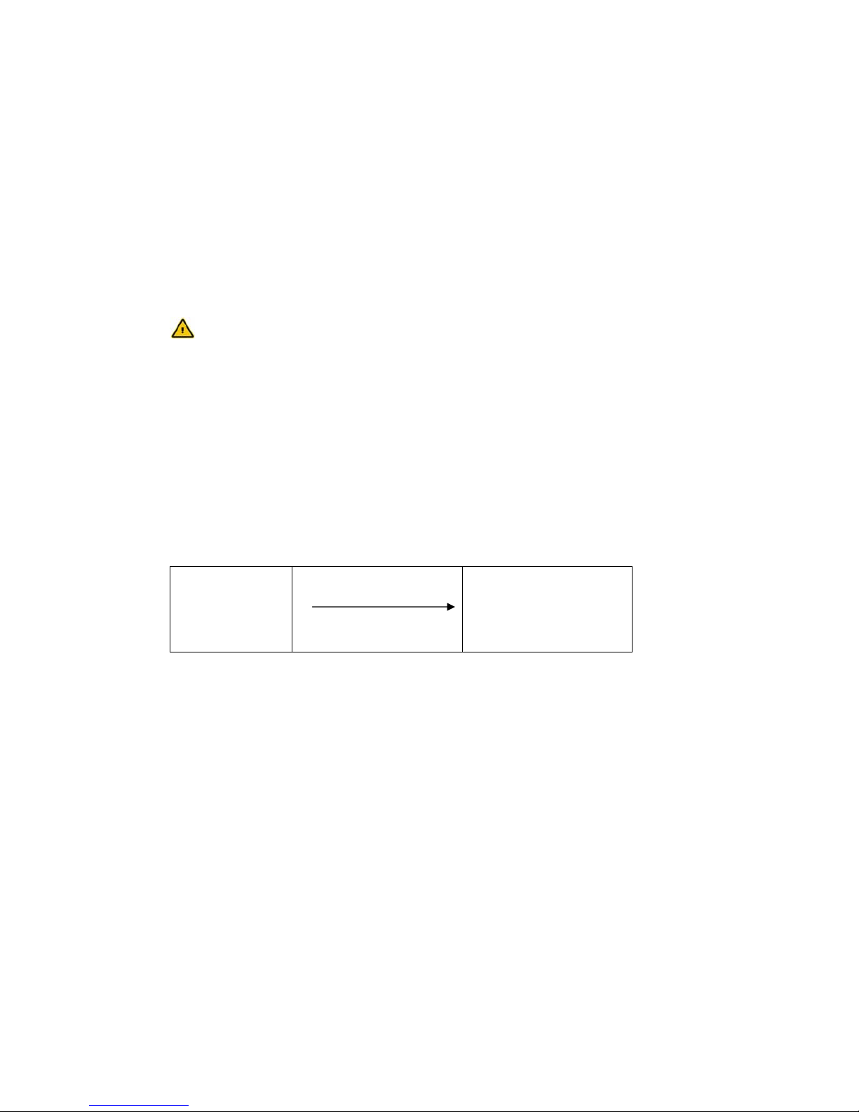
5.2.4 Hardware Data Flow Control with RTS/CTS
Hardware Data Flow Control with the Modem (CTS):
Modem
RS232 Cable
CTS Line
Application
(E.g.: PC or control)
When the input buffer of the modem exceeds a certain fill state, the
modem will set the CTS line to OFF. This indicates to the application
not to send any data.
After the modem has operated the input buffer so far that the XON
buffer falls below a certain fill state, it switches the CTS line back ON
and reports to the application that it is ready to receive data again.
AT\N1
AT&K3 AT&R1
Page 22
22 Helmholz Modem 56k small/Modem 56k USB small
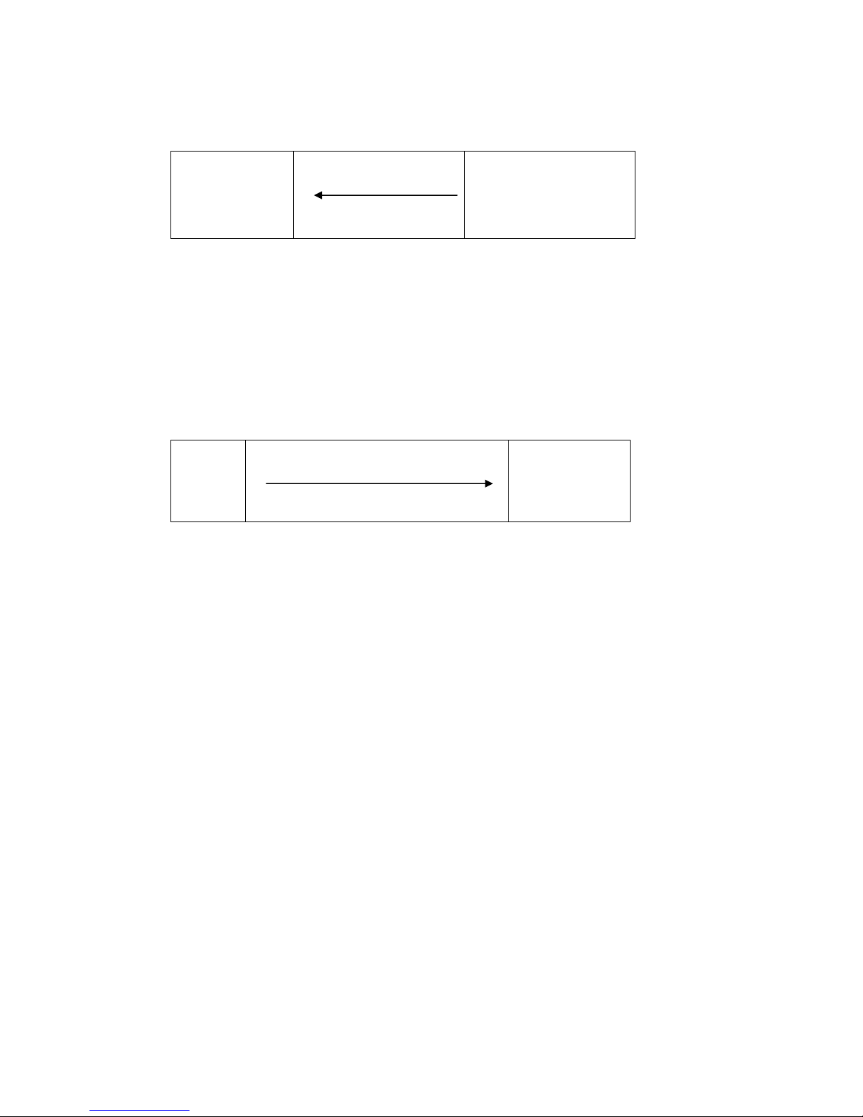
Hardware data flow control with the application (RTS):
Modem
RS232 Cable
RTS Line
Application
(E.g.: PC or control)
The application sets the RTS line to OFF to request from the modem
to interrupt the data transmission.
It will depend on the according application software if the RTS/CTS
lines can be operated.
The application sets the RTS line to ON to request data from the modem.
5.2.5 Software data flow control XON and XOFF
Modem
Send data
XON or XOFF character
Application
(E.g.: PC or
control)
When the input buffer of the modem exceeds a certain fill state, the
modem will insert an XOFF character into the data stream to the application. This character will cause the application to send no more data.
It will depend on the according application software if the RTS/CTS
data flow control is supported.
After the modem has processed the input buffer so far, it will insert a
XON character into the data stream. This character will cause the application to send data to the modem again. Analogously, the applicaiton
can control the data stream from the modem to the application.
The XON/XOFF method is only available when the transmitted data do
not contain the characters XON or XOFF, which usually appear only in
actual ASCII texts (7 bit). When binary data (programs, …) are transmitted, also for BTX operation or in the XMODEM transmission protocol,
for example, occasionally appearing XON or XOFF characters would disturb the operation.
AT&K AT&R
AT&K4
Page 23

Helmholz Modem 56k small/Modem 56k USB small 23
5.2.6 Reset
There are three reset options:
¾ After the power supply has been interrupted for a short time.
¾ After the terminal RESET is connected to the terminal GND
¾ With the help of the terminal program
After the hardware reset, load the user profile 0
After the hardware reset, load the user profile 1
5.2.7 Dial-up delay
The standard TBR21 applies to all public phone networks in EU
countries (Belgium, Denmark, German, Finland, France, Greece,
Great Britain, Ireland, Italy, Luxembourg, Netherlands, Austria,
Portugal, Sweden, Spain), as well as in Switzerland, Liechtenstein,
Norway and Iceland.
According to the TBR 21 regulations, after 12 futile dial-up attempts each further dial-up is locked within 2 hours. In this case,
the modem must be temporarily switched off.
The counter is automatically reset after each successfully established connection.
After the connection has been established, a dial delay of 5 seconds is observed.
ATZ0 ATZ
ATZ1
Page 24

24 Helmholz Modem 56k small/Modem 56k USB small
5.3 Error correction
The modem masters the V.42 error correction protocol including
the Microcom Networking Protocol Levels 2/3/4 (MNP2, MNP3,
MNP4) and the data throughput optimization MNP10.
5.3.1 V42 Error Correction
The V.42 error correction includes the protocols LAPM (Link Access Procedure for Modem) and MNP 4. LAPM is the preferred error correction.
MNP 4 is supported for compatibility reasons with other MNP
modems. Both methods determine frames to transfer net data and
use CRC (Cyclic Redundancy Check) check sums for error tests.
In V.42, the possibility exists to have the modem identify if the
partner is a V.42 modem, a MNP modem, or a modem without error correction. The modem can then autonomously adjust to the
partner.
5.3.2 MNP 2/3/4 error correction
The maximum block size can be set to either
64 byte
128 byte
192 byte
and 256 byte.
The MNP error correction can either be set automatically or activated via AT commands.
5.4 Data compression
The modem will identify the type of data compression used by
the other modem, or it is fixed on a certain type or no data compression.
Data compression is only available for error corrected connections.
To be able to use data compression, both sides (sender and recipient) must be able to recognize the same data compression mode.
AT\A0
AT\A1
AT\A2
AT\A3
AT\N<n>
AT%C<n>
Page 25

Helmholz Modem 56k small/Modem 56k USB small 25
5.4.1 V.42bis Data Compression
Switch on V.42bis data compression
Switch off V.42bis data compression
V.42bis data compression may only be performed for a V.42 connection (LAP-M or MNP 4). First of all, V.42bis generates a socalled dictionary for the data compression, which contains frequently used character sequences. After that, only short references to these character sequences and not the complete character sequences are transmitted to the other modem.
V.42bis cannot re-pack packed data.
5.4.2 MNP 5 Data Compression
The modem masters the Microcom Networking Protocol Level 5.
MNP 5 data compression can only be performed for an error corrected MNP 4 connection. MNP 5 replaces frequently used characters by shorter characters, so-called tokens.
MNP 5 cannot re-pack packed data.
5.4.3 V.44 Data Compression
The V44 data compression offers better compression of typical
internet content than V.42bis. V.44 also requires an error corrected connected, just as V.42bis, and cannot re-compress already
compressed data.
Switch off V.44 data compression
Switch on V.44 data compression
AT%C2
AT%C3
AT%C3
AT%C0
AT+DS44=0
AT+DS44=3
AT%C1
AT%C3
Page 26

26 Helmholz Modem 56k small/Modem 56k USB small
5.5 Selective Call Answer
If the selective call acceptance is activated, the modem will
only accept calls from certain callers. The identification of
permitted callers takes places via the caller ID transmission
(CLIP). This must, however, be supported by the phone
system or the exchange connection, where the modem is
connected to.
Activate the selective call acceptance
Deactivate the selective call acceptance
Display a complete list of saved phone numbers for the selective call answer.
Delete the complete phone list for the selective call acceptance.
The list of phone numbers has 8 storage locations altogether (N0 to N7). Only if the transmitted phone number
<nr> matches a phone number that was entered in the
list will the modem accept the call according to the settings.
E.g.: Store phone number 1234 at storage location 6.
The memory N<n> accepts all phone numbers ending in
<nl>.
Our first example activates all phone numbers ending in
941586920.
The following phone numbers are activated:
0941586920, 00490941586920 und +49941586920
Our second example activates all phone numbers ending
in 0941586920.
Only the phone number 0941586920 is activated.
AT&A1
AT&A0
AT*N7=941586920
AT*N?
AT*N99=
AT*N<n>=<nr>
AT*N6=1234
AT*N<n>=<nl>
AT*N7=0941586920
Page 27

Helmholz Modem 56k small/Modem 56k USB small 27
The list of phone numbers may also contain wildcards “'*”.
This allows the activation of entire blocks of phone numbers.
The wild card character (“*”) replaces exactly 1 character of
the phone number.
Our example will activate all phone numbers that start with
94158692** and have 2 more digits (e.g.: an extension).
The phone number may not contain separators
such as brackets or space characters.
The phone numbers can be deleted individually in two different ways.
¾ Delete the entered phone number
E.g.: Delete the number stored at the storage location 5
¾ Overwrite the storage location with a new phone num-
ber.
E.g.: Storage location 5 with phone number 456.
Display the last phone number whose call was rejected. This
phone number is not saved in the power fail-safe memory of
the modem, i.e. after a restart of the modem the display will
be empty.
AT*N<n>=
AT*N5=
AT*N<n>=94158692**
AT*N6=94158692**
AT*N<n>=456
AT*N5=456
AT%N
Page 28

28 Helmholz Modem 56k small/Modem 56k USB small
5.6 Send Messages
Note: The sending time of an SMS from the sender to a recipi-
ent depends on the pertinent provider of the service
number. Depending on the degree of utilization and
the time of day, an SMS may be on the way for an extended period.
5.6.1 Transmission Configuration
The modem can not only send the alarm message to another analogue modem, but also to a mobile phone as an SMS. Currently
GSM900 and GSM1800, and SMS to fixed networks, fax and email.
The maximum text length is 160 characters.
Protocol settings – see table -
Transmission Protocol Data
format
Example
Data Connection
AT*M0
SMS to Mobile PET 8N1
D1 or
E Network
AT*M1
SMS to Mobile UCP 7E1
AT*M2
SMS to Mobile PET 7E1
AT*M3
SMS to Mobile UCP 8N1 D2 network
AT*M4
Fax
AT*M5
SMS to Mobile
or Fixed Network
AT*M6
Enter the service number of the network provider to send SMS, or
the phone number for fax and data connections
Definition of the collective message
Definition of the variable alarm texts and phone numbers to send
SMS (alarm text 1 or 2). After this command is activated, the modem will query the alarm text.
AT*M<n>
AT*
V
AT&Z0=<phone number>
AT*V1
AT*V2
Page 29

Helmholz Modem 56k small/Modem 56k USB small 29
The modem will reply with
and expects the input of the phone number and the alarm text in
the form
For the transmission, the variable part (maximum of 80 characters) will be attached to the common part (maximum of 160
characters) of the collective message. Of the maximum of 240
characters, the first 160 characters are sent as SMS.
Some network providers support SMS forwarding to a fax machine
or an e-mail address.
All necessary information is available from the customer service of
the provider.
Please find an overview of the required settings for network providers in German-speaking countries in the attachment.
5.6.2 Triggering
Manual triggering of the collective message
Manual triggering of the alarm messages 1 or 2 via the AT command.
For the transmission, all in all, 3 attempts (factory default) are
made. These values (1...12) can be changed with the S registry S13.
When the alarm is triggered via SMS, the modem will return a
status
¾ Message was successfully sent
¾ Error during the message transmission
After the message was sent, the connection is terminated.
5.6.3 Fax logging
All alarm messages can also be sent to a fax number for logging
reasons.
AT%A<n>
new text:
<phone number,
text>
AT%A
ATS13=n
OK
ERROR
AT&Z3=<phone number>
Page 30
30 Helmholz Modem 56k small/Modem 56k USB small
5.7 Remote Configuration (Remote Control)
5.7.1 Mode of Operation
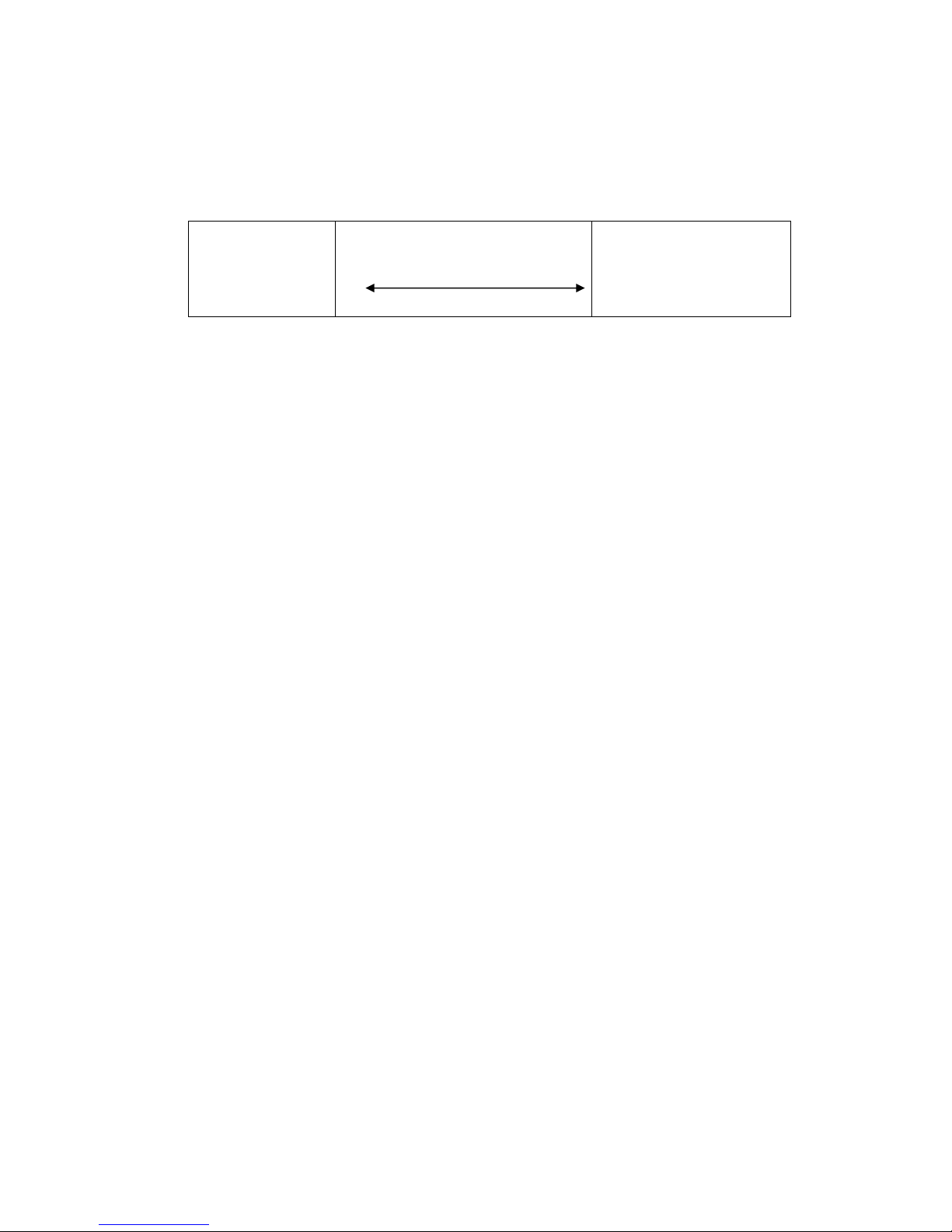
Modem 1
(local modem)
Phone line
Modem 2
(remote modem)
To switch into the remote configuration mode, a data connection
must be established between the modems. A certain connection
type is not mandatory, we recommend, however, using only error
corrected connections for remote configuration, to avoid transfer
errors for the commands.
The local modem is not required to master any remote configuration type.
5.7.2 Remote modem preparation
Auto answer
Deactivate security callback
Release modem for remote configuration
Save entry
5.7.3 Remote modem password change
Change password
Enter old password (default: QWERTY)
Enter new password
Re-enter new password
AT*C
OLD PASSWORD
QWERTY
ATS0=2
AT&Z1=
AT*R1
AT&W0 AT&W1
NEW PASSWORD
Confirm
Page 31

Helmholz Modem 56k small/Modem 56k USB small 31
5.7.4 Start of the remote configuration at the local modem
Dial the modem
The modem will establish a successful connection
Switch to remote configuration mode
Prompt for entering the password
Enter password (default: QWERTY)
If the entry was successful, the remote modem will send the input prompt
5.7.5 Reduced command set
Some commands may not be executed during remote configuration
and
will result in the following response:
5.7.6 Terminate remote configuration
Before you complete the remote configuration, save all settings in
profile 0 or 1.
Several commands may be used for termination.
Return to online mode without software reset
Software reset with interruption of all connections
The modem loads the user configuration 0 or 1.
****
Remote Access
Remote Passwort:
ATA ATD
ATO AT/B
AT&F
AT*E AT*X
ATZ0 ATZ1
ATD <phone number>
Connect…
QWERTY
>
ERROR
AT&W0 AT&W1
Page 32

32 Helmholz Modem 56k small/Modem 56k USB small
5.8 Access Control
5.8.1 Password
To protect from unauthorized access via the phone line, the
modem may be protected by a password. This password is used
to establish a data connection, as well as for security callback
and remote configuration
The default setting is QWERTY.
5.8.2 Data Connection
An incoming connection is only released after the caller has entered
the password.
Activate password protection
Deactivate password protection
5.8.3 Security callback
The feature Security Callback will cause the remote modem to
hang up and call back a preset number.
This function will only be performed after a password has been
entered and is therefore a safe protection against unauthorized
access.
5.8.3.1 Preparation
As a preparation, security callback is activated by saving the call
back number in the phone number registry of the modem that is
calling back.
The deactivation takes place by deleting the call back phone
number.
AT*P1
AT*P0
AT*C
AT&Z1=<phone number>
AT&Z1=
Page 33

Helmholz Modem 56k small/Modem 56k USB small 33
5.8.3.2 Operation
Establishing a connection to the modem.
The connection to the modem is established.
The modem responds to an incoming call.
You must now enter the “Remote Password”, which is
identical to the password for the remote configuration.
(default: QWERTY)
After the password has been entered correctly, the modem hangs
up and after about 10 seconds dials the stored phone number.
Altogether, 3 dialing attempts with a pause of 10 seconds between each attempt are performed.
If the entered password was incorrect, the connection is terminated and thus prevents unauthorized access to the connected
device.
After that, a normal data connection is established.
ATD <Renumber>
OK
No Carrier
Callback in Progress
Connect
SECURITY CALLBACK
REMOTE PASSWORD:
QWERTY
No Carrie
r
Page 34

34 Helmholz Modem 56k small/Modem 56k USB small
5.9 Data Transmit Controller (Idle Connection Control)
The Data Transmit Control (DTC) is a function integrated in the
firmware which monitors the data transmission in online mode.
This function prevents the modem to stay online for an unlimited amount of time, although no data is being transmitted
anymore.
5.9.1 Activation
The activation takes place in the S15 registry. Any time period
between 1 and 255 seconds may be set.
5.9.2 Mode of Operation for the “Timer”
The timer will run immediately after the modem goes off-hook.
After the set time has been reached, a RESET is performed.
The timer is reset by each byte that is sent via the serial interface.
Note: The timer will run immediately after the modem
goes off-hook. We therefore strongly recommend to
not setting any times below 30 seconds.
In remote mode, idle connection control at the modem must be deactivated to prevent the connection
from being interrupted after the timer has run out.
The remote data transmission will not reset the
timer.
ATS15=<n>
Page 35
Helmholz Modem 56k small/Modem 56k USB small 35
5.10 Priority Circuit for Modems with Phones Connected in Series
The HELMHOLZ Modem 56k small gives a phone connected in series priority, to make sure it interferes as little
as possible with the usage of the phone connection.
Command Function 1 Function 2 Function 3
(Chap. 5.10.1) (Chap. 5.10.2) (Chap. 5.10.3)
AT-STE=0 == == == (default)
AT-STE=1 √ == ==
AT-STE=2 == √ ==
AT-STE=3 √ √ ==
AT-STE=4 == == √
AT-STE=5 √ == √
AT-STE=6 == √ √
AT-STE=7 √ √ √
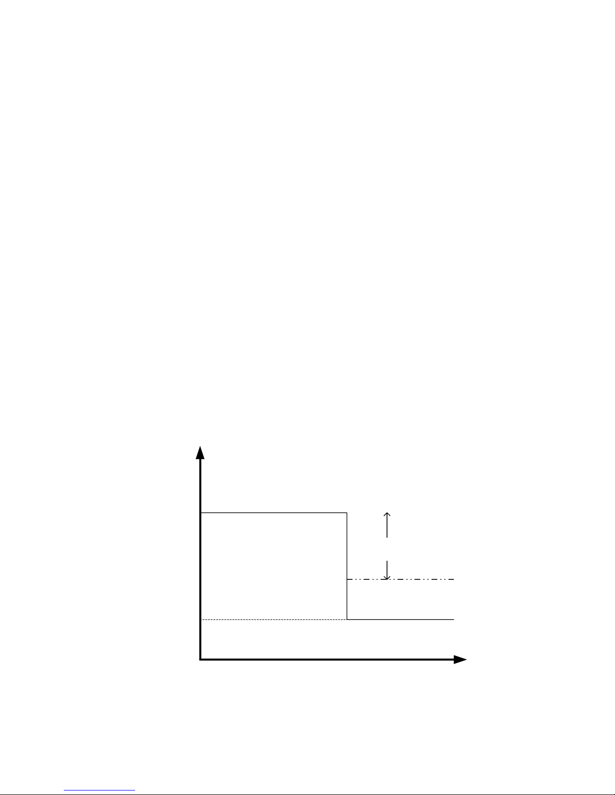
5.10.1 Detecting a busy phone line
During a dial-up attempt, the model detects the busy phone
line. The modem reports
Changing the loop voltage to detect the function – Detection
of a busy line (U1) – can be set with the help of AT commands.
U1
Loop voltage prior
to the connection.
Voltage
Loop voltage for
busy phone line.
Time
LINE IN USE
AT-TTE=U1, U2, U3
Page 36
36 Helmholz Modem 56k small/Modem 56k USB small
5.10.2 Going off-hook on account of a telephone connected in series
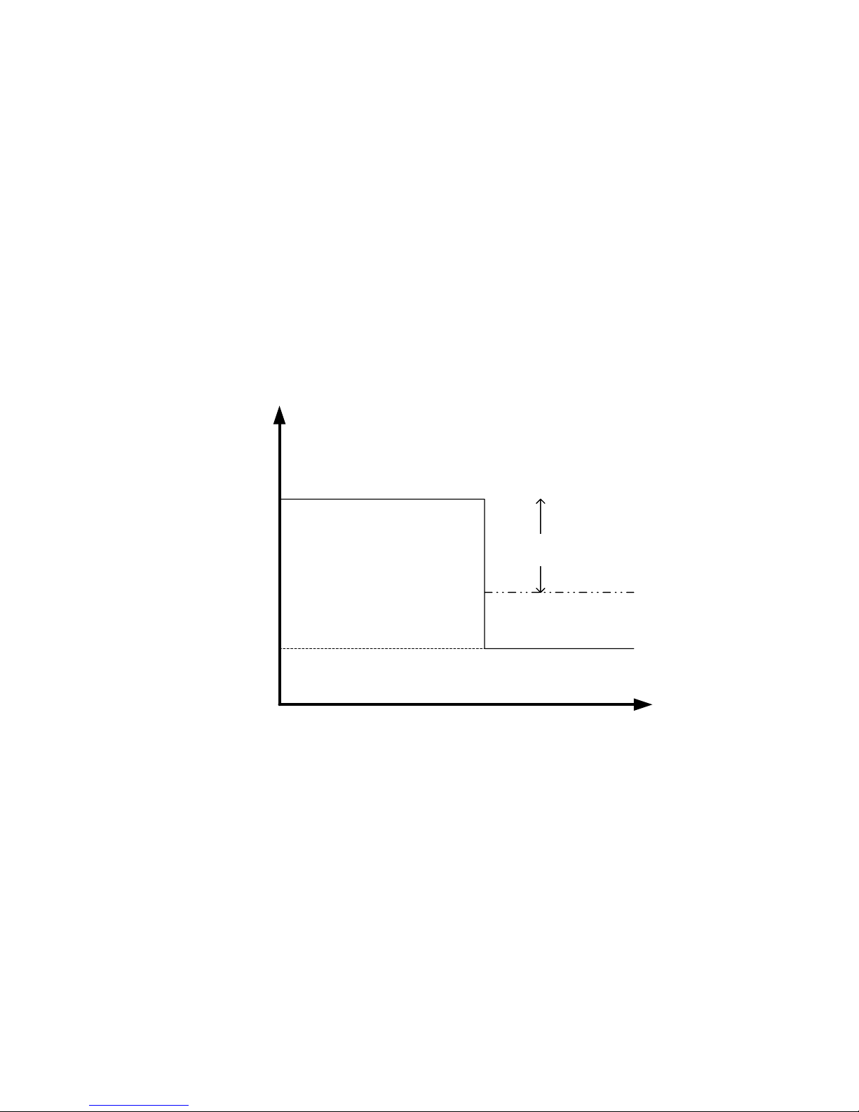
If a telephone connected in series goes off-hook during an existing modem connection, the modem will immediately terminate
the connection.
The telephone is connected to the line and receives a dialing
tone.
In the registry S86, the value is set to 25.
When the phone connection is terminated, the modem will not
establish a new connection.
Changing the loop voltage to detect the function – Off-hook on
account of a telephone connected in series (U2) – can be set with
the help of AT commands.
Note: The detection starts immediately after the hand-
set is picked up. To access the exchange, simple
analogue phone systems often connect the modem per contact directly with the exchange,
which results in a strong change or polarity reversal of the loop voltage. For some analogue
phone systems, this may result in an erroneous
detection. Off-hook detection is therefore not
recommended in connection with analogue
phone systems.
U2
Loop voltage prior
to the connection.
Time
Voltage
Loop voltage after
a telephone connected in series
goes off-hook.
ATS86=25
AT-TTE=U1, U2, U3
Page 37
Helmholz Modem 56k small/Modem 56k USB small 37
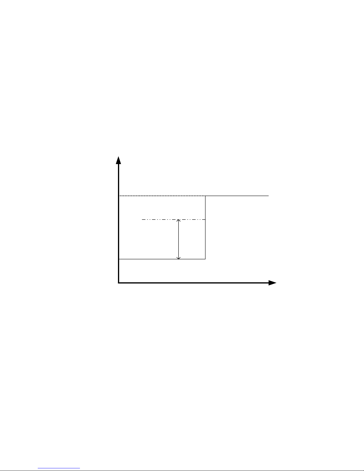
5.10.3 Remote Terminal Connection Abort
When the remote terminal aborts a connection, the modem will
immediately hang up.
In the registry S86, the value is set to 25.
Changing the loop voltage to detect the function – Remote Terminal Connection Abort (U3) – can be set with the help of AT
commands.
Note: This detection is based on the change of the loop
voltage (AT-TTE=U1, U2, U3). It will not work for
all connections. ISDN phone systems in particular often suppress the hang-up noise.
U3
Time
Voltage
Loop voltage after
the connection is
terminated.
Loop voltage during the connection.
ATS86=25
AT-TTE=U1, U2, U3
Page 38
38 Helmholz Modem 56k small/Modem 56k USB small
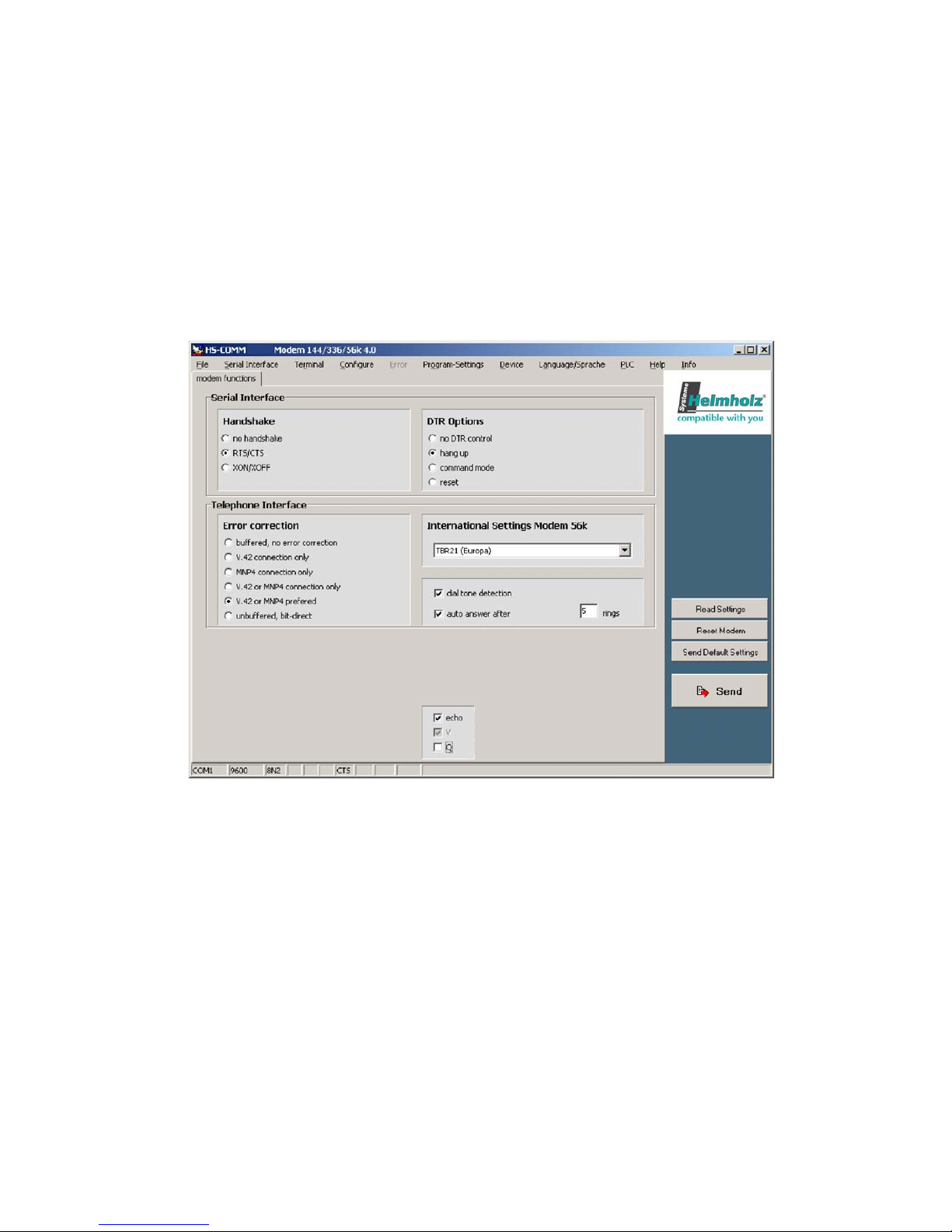
6 Configuration Software HSComm
The configuration of the HELMHOLZ modem takes place via AT commands which are
entered by a terminal program or a control program in the form of character sequences. For a simple set-up, all basic functions of the HELMHOLZ modem can be entered without knowing the individual commands and their parameters, using the configuration software.
The software can be installed on all common Microsoft Windows operating systems. A
terminal window to enter commands directly is available.
At the start or via the menu Device
Æ
Device, HSComm verifies the connected device
and displays the device name and the firmware in the right top program window. By
default, only those settings can be selected which are implemented in the identified
device.
The buttons in the right column can be used to select the current settings, to restart
(reset) the device or to set the default options. The selected configuration of the parameters is only sent to the HELMHOLZ modem after you click the button SEND.
File menu: Configurations can be saved as files and re-loaded at a later date.
When an error occurs while transmitting a configuration to the HELMHOLZ modem,
these are displayed in the Error menu.
Hitting the key F1 will automatically display a help window regarding the currently
selected topic.
Page 39
Helmholz Modem 56k small/Modem 56k USB small 39
7 Operation with a PLC
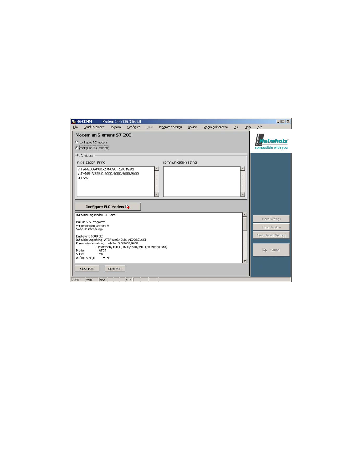
The HELMHOLZ Modem 56k small has been tested for the most common
PLC systems on the market.
The documentation (Application Notes) of the settings required for the respective PLC can be queried at Systeme Helmholz GmbH (E-mail:
HSComm offers a range of recommended settings for the modems connected at the PLC or the PC at the control center.
If control is selected in the menu PLC, for both modem locations the necessary settings and a user prompting are displayed as text. The user can adjust the settings.
The commands Configure PLC modem and Configure PC modem transmit
these settings to the connected modem.
Page 40
40 Helmholz Modem 56k small/Modem 56k USB small
8 Firmware Update
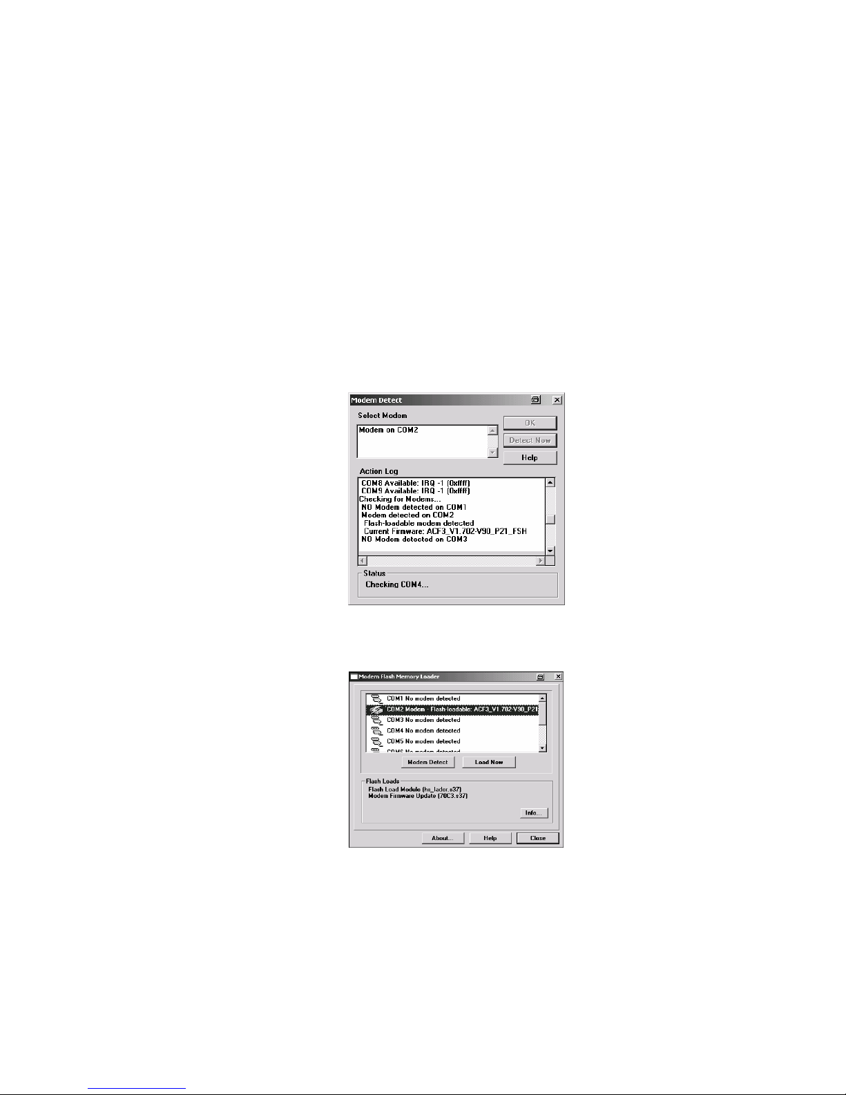
8.1 Flashcom.exe
This function enables firmware updates of the modem without
switching the EEPROM. The new version is available from your
service partner.
Query of the used firmware
Unpack the file into any directory on the PC and start Flashcom.exe.
The program will automatically search for the connected modem.
Select the according HELMHOLZ Modem and start the update.
ATI4
Page 41
Helmholz Modem 56k small/Modem 56k USB small 41
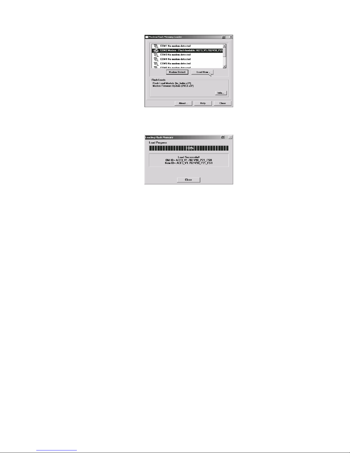
Close the window when the update is completed.
8.2 Terminal Program
8.2.1 Requirements
For the firmware update, you will need a PC and a terminal
program. The terminal program must be able to perform an
ASCII upload (ASCII data transmission protocol). Setting the
hardware flow control is mandatory. For safety reasons, any
interpretation of characters (e.g.: TAB, CR, BS...) by the ASCII
upload protocol must be prevented.
The baud rate must be between 9,600 baud and 57,600 baud.
Other baud rates may lead to errors. The loading procedure
takes about 2 to 3 minutes for 57,600 baud; for lower baud
rates accordingly longer.
8.2.2 Activation and Process
Start of the flash update
The modem sends a response
The update is performed in two steps:
Download initi
a
t
ed…
Download Flashc
o
d
e
T
ransfer file with the help
of the terminal program.
AT**
Page 42
42 Helmholz Modem 56k small/Modem 56k USB small
¾ ASCII upload of the file HS_LADER.S37
¾ ASCII upload of the firmware (xxxxxxxx.S37)
The process is finished as soon as the loading procedure
is completed.
Monitoring of Results:
The transfer process is indicated by dots on the monitor
(of the terminal program).
Note: For the terminal program Telix, the delay
settings between the character and the
lines must be set to “0” for the ASCII protocol.
9 AT Command Set
All HELMHOLZ communication devices are controlled internally via AT commands.
A terminal program is integrated in the HSComm. The AT commands can be directly
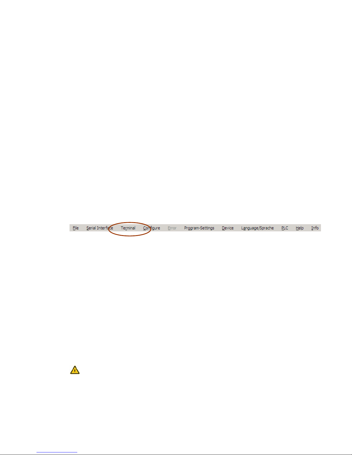
entered at the menu item “Terminal”.
Alternatively, we recommend the terminal program TeraTerm by T. T. Teranishi. The
free software can be downloaded at
http://www.vector.co.jp/authors/VA002416/teraterm.html.
Each AT command starts with the letters AT and ends with a “Carriage Return” (CR).
Capital and small letters will both be accepted, but the leading characters must be either ‘AT’ or ‘at’. The command line is evaluated after the modem receives a return
command. In the description, a parameter with the letter “n” means that it can have
various values.
For example, ATL<n>, where 'n' can have the value 0 or 3, e.g. ATL2 (medium volume). For commands which expect a parameter but don't have a parameter, the modem will automatically assume the parameter 0. For example, the commands ATZ and
ATZ will have the same effect.
The factory settings are marked “(default)”.
The standard end character is “return” (0Dh) or “<CR>“. “Return” may not be
entered after “****” or “+++”.
The commands are acknowledged with “OK” or “ERROR”. A com-
mand that is being edited will be interrupted by any further incoming character. Therefore, the next command must wait for acknowledgement to avoid the deletion of the current command.
Device successfully
programmed
Page 43
Helmholz Modem 56k small/Modem 56k USB small 43
Note: The installation of the driver files creates a
virtual serial interface (COM port) on the computer. The PC will treat this interface like a "real"
serial interface. All commands and functions in
this manual which relate to serial interfaces can
also be used for the version HELMHOLZ Modem
56k USB small.
9.1 Overview AT Commands
Command Description
AT** Start of the flash load function
ATA Answer mode
The modem is switched into response mode. This is only effective in Germany,
if the connected phone goes off-hook or if a call comes in.
A/ Repeat the last command
The last command is repeated.
AT\A<n> Select maximum MNP block size
Define maximum block size for error corrected MNP transmissions.
AT\A0 64 byte
AT\A1 128 byte (default)
AT\A2 192 byte
AT\A3 256 byte
AT*A<n> Automatic call acceptance on/off
AT*A0 Call acceptance is blocked, irrespective of S0
AT*A1 Call acceptance according to S0 (default)
Note: see also S-Registry 36, bit 7
AT&A<n> Selective Call Answer On or Off
To evaluate selective call answer, the phone number must be transmitted (CLIP).
The following countries support the “CLIP” function:
Australia, Belgium, China, Denmark, Germany, Finland, Great Britain, Hong
Kong, India, Ireland, Iceland, Italy, Canada, Korea, New Zealand, The Nether-
lands, Norway, Austria, Sweden, Singapore, Spain, Taiwan, USA.
AT&A1 Switches the selective call answer ON
AT&A0 Switches the selective call answer OFF (default)
The AT&A setting is saved in AT&W.
AT%A<n> Send alarm text manually
Manual triggering of the message. After the message is sent, the device responds
with OK (success) or ERROR (failure).
Note: see also AT*V<n>
Page 44

44 Helmholz Modem 56k small/Modem 56k USB small
Command Description
AT\B<n> Send “break” to the other modem
For connections that were not error corrected the modem sends a break signal to
the other modem. The length of the signal is: the specified parameter times 1/10
of a second.
For error corrected connections, the modem sends a break signal according to
the active error correction protocol without considering a parameter specifica-
tion.
If no connection is established or if a fax connection is active, an error message
is displayed.
AT\B1 1/10 second break signal
AT\B2 2/10 second break signal
AT\B3 3/10 second break signal
AT\B4 4/10 second break signal
AT\B5 5/10 second break signal
AT\B6 6/10 second break signal
AT\B7 7/10 second break signal
AT\B8 8/10 second break signal
AT\B9 9/10 second break signal
AT%B<n> Switch key abort on and off during connection
AT%B0 Key abort is active. Each character on the Tx line will result in an
interruption of the connection setup. (default)
AT%B1 Key abort is deactivated. The connection setup cannot be inter-
rupted manually.
A connection setup can only be interrupted via DTR drop, internal canceling of
the modem (NO DIALTONE, BUSY) or Timeout (NO CARRIER). (S-Registry 36 Bit
6)
AT%C<n> Enable data compression
Enable/disable a data compression type
The modem can only perform data compression for error corrected connections.
AT%C0 No data compression enabled
AT%C1 MNP 5 data compression enabled
AT%C2 Enable V.42bis and V.44 data compression
AT%C3 Enable MNP 5 and V.42bis data compression (default)
Page 45
Helmholz Modem 56k small/Modem 56k USB small 45
Command Description
AT*C Remote configuration password
This password secures the remote configuration as well as incoming data connections (see AT*P) and security callback.
OLD PASSWORD Requires the old password (default: QWERTY). Wrong input
leads to ERROR.
NEW PASSWORD Enter the new password with 6 to 12 characters.
CONFIRM Repeat the new password. Wrong input leads to ERROR.
OK The password is immediately stored in the EEPROM.
AT&C<n> DCD (CT109) behavior
Behavior of the RS232 DCD output of the modem.
AT&C0 DCD is always ON
AT&C1 DCD follows the carrier signal of the phone line (default)
AT+CMGF=<n> Set the SMS dispatch format with AT+CMGS
AT+CMGF=0
Sets the PDU mode for the SMS dispatch via AT+CMGS (default).
AT+CMGF=1
Sets the text mode for the SMS dispatch via AT+CMGS (default).
AT+CMGS SMS dispatch directly via AT command
Depending on the setting of AT+CMFG, the command AT+CMGS will have a different syntax.
Setting AT+CMGF=1 (text mode):
AT+CMGS="phone number"
The modem returns the “>” character and awaits the SMS text (up to 160 charac-
ters), ending with an EOF character (0x1A or STRG-Z).
Notes:
Depending on the provider, the phone number must be entered in the format
"0941xxxx" or "49941xxxx" (see AT*M and/or AT&Z2).
- After the sending procedure was successful, the modem will return "+CMGS: 000"
Setting AT+CMGF=0 (PDU mode):
AT+CMGS=<PDU string length>
The modem returns the character “>” and awaits the PDU string, ended with an
EOF character (0x1A or STGR-Z).
Notes:
- Depending on the provider, the phone number must be entered in the format
"0941xxxx" or "49941xxxx" (see AT*M and/or AT&Z2).
- "Numbering Plan" is ignored.
- The service center is defined by AT&Z0, the SCA field in the PDU string is ig-
nored.
- Message header, confirmation SMS and validity period are not supported.
- Data coding scheme: Only the “default alphabet” is supported.
- After the sending procedure was successful, the modem will return "+CMGS:
<MR>" where <MR> is the message reference defined in the PDU string.
Page 46
46 Helmholz Modem 56k small/Modem 56k USB small
Command Description
AT+CPIN? Dummy command for GSM compatibility
AT+CPIN? responds with "+CPIN: READY"
This command only serves for the purpose of compatibility with applications for
GSM devices.
AT+CREG? Dummy command for GSM compatibility
AT+CREG? responds with "+CREG: 0,1".
This command only serves for the purpose of compatibility with applications for
GSM devices.
AT+CSQ Dummy command for GSM compatibility
AT+CSQ responds with "+CSQ: 20,99".
This command only serves for the purpose of compatibility with applications for
GSM devices.
AT+CPMS? Dummy command for GSM compatibility
AT+CPMS? responds with "+CPMS: "MT",8,40,"MT",8,40,"MT",8,40".
This command only serves for the purpose of compatibility with applications for
GSM devices.
Page 47

Helmholz Modem 56k small/Modem 56k USB small 47
Command Description
ATD<n> Dial
The modem goes off-hook and dials according to the transmitted dialing string.
After the dialing procedure, the modem attempts to establish a connection. If
the ATD command was performed without a dialing string, the modem goes off-
hook and attempts to connect to the other modem (without dialing). The be-
havior of the modem depends on the activation of the line current recognition
(see ATX command).
The execution of the ATD command also depends on when the last dialing at-
tempt was performed.
In the mode AT+FCLASS=0, the modem acts like a data modem. It attempts to
connect to another data modem. This attempt is repeated until the waiting pe-
riod that was specified in the S7 registry has expired.
If this period is exceeded, the modem hangs up and the following error message
appears: NO CARRIER.
In the mode FCLASS=1 or =2, the modem acts as a fax modem. It attempts to
connect to another fax or fax modem. (The modem goes into receive status
HDLC V.21 channel 2, as if the command AT+FRH had been executed.)
The following characters may be transmitted as parameters (brackets, punctua-
tion marks, spaces and semicolons are ignored):
0 to 9 The digits from 0 to 9
* The asterisk: Only for tone dialing
# The hash: Only for tone dialing
A-D The inband signaling characters A, B, C, D
P Pulse dialing mandatory: Pulse or tone dialing is required accord-
ing to the region.
T Tone dialing mandatory: Pulse or tone dialing is required accord-
ing to the region.
W Wait for dialing tone: The modem waits for the dialing tone be-
fore it starts to dial. If no dialing tone was detected within the pe-
riod specified in the S6 registry, the modem hangs up and an er-
ror message is displayed.
@ Waiting for silence: The modem waits at least five seconds for
silence in the line, before it executes the next character from the
parameter string. If this five second silence can not be detected
and the abort period in the S7 registry has not been exceeded, the
modem terminates the connection displaying the message: NO
ANSWER.
If busy signal recognition was activated, the modem terminates
the connection displaying the message: BUSY.
If a response tone from the other modem is received during the
waiting period, a connection is established.
Page 48

48 Helmholz Modem 56k small/Modem 56k USB small
Command Description
ATD<n>
C
ONTINUATION
‚ Dial tone delay: The modem performs a dial tone delay before it
executes the next character of the parameter string. The delay
length is defined in the S8 registry.
L Last number re-dialing.
; Return to the input mode after dialing. It is added to the end of
the dialing string and causes the moden to return to the entry
mode when it reaches “;” (with: message OK). This enables the
input of AT commands even with a receiver off-hook. The additional AT commands can follow in the same input line after the
“;” or they can be transmitted to further input lines. The ATH
command will abort the connection and the receiver is hung up.
S=n Dialing the n-th number from the number pool, which was set up
with the AT&Z<n> command.
! If the character ”!” is a part of the dialing string, the modem will
hang up within the time frame determined in S29 and then goes
off-hook again.
^ Suppresses the sending of a ringing tone.
ATD12345; The semicolon (;) causes the return to the input mode after dial-
ing.
Default: Ringing tone is sent for fax operation. No ringing tone for data
operation.
( ) Are ignored: They are just used as an outline.
- Are ignored: They are just used as an outline.
‚ ‚ Space characters are ignored: They are just used as an outline.
Examples:
ATD12345 Dial the phone number 12345
ATDP12345 Dial the phone number 12345 with the pulse dialing method
ATDT12345 Dial the phone number 12345 with the tone dialing method
ATX3D0W12345
For PBXs, which connect to the exchange line using the prefix 0
(or 9): First, blind dialing is activated by: X3 (see the command
„ATX3“) to be able to dial a leading 0 without hearing a dialing tone.
After 0 has been dialed via: D0 dialing tone recognition can be
switched on again using the parameter: W. The modem thus waits
for the dialing tone and continues with the rest of the dial-up
(via: 12345) only after hearing the dialing tone. Waiting for the
dialing tone may be omitted. In this case, the dialing command is
ATX3D012345.
Page 49
Helmholz Modem 56k small/Modem 56k USB small 49
Command Description
AT&D<n> DTR (CT108/2) behavior
DTR (CT108/2) behavior - Monitoring on/off transitions of the RS232 DTR line
of the PC.
AT&D0 DTR is ignored. Allows the operation with PCs which do not run
DTR.
AT&D1 A DTR on/off transition causes the modem to react as if it had
received an abort sequence +++. The modem switches to the in-
put mode without hanging up.
AT&D2 A DTR on/off transition causes the modem to hang up. Going off-
hook automatically is not possible. (default)
AT&D3 A DTR on/off transition causes the modem to perform a reset as if
an ATZ command had been executed. A preceded AT&Y com-
mand decides if either the default 0 or 1 is loaded.
AT+DS=<n> Activate/deactivate V.42bis data compression
AT+DS=0 Deactivates V.42bis data compression
AT+DS=3 Activates V.42bis data compression (default)
AT+DS44=<n> Activate/deactivate V.44 data compression
AT+DS44=0 Deactivates V.44 data compression
AT+DS44=3 Activates V.44 data compression (default)
ATE<n> Command entry Echo
This command toggles the responses, which the modem creates as reactions
from application commands (Echo), ON or OFF.
ATE0 Switch off Echo
ATE1 Switch on Echo (default)
AT%E<n> Automatic Retrain
When transmission problems occur, the modem executes a retrain procedure.
After three unsuccessful retrain attempts, the modem will hang up.
AT%E0 Retrain not allowed
AT%E1 Retrain allowed
AT%E2 Fall back, fall forward allowed (default)
AT%E3 Fast fall back, fall forward. Is not supported by all modem types.
AT*E Terminate remote configuration
The command AT*E terminates a remote configuration.
AT&F Loading the default factory settings
The modem loads the default factory setting from the internal, nonvolatile
memory. This puts the modem into a defined basic state. AT&F also overwrites a
part of the S registry.
The HELMHOLZ Modem 56k small has two factory defaults (AT&F0, AT&F1).
Page 50
50 Helmholz Modem 56k small/Modem 56k USB small
Command Description
AT+GCI=<N> Set country code
The command AT+GCI allows the customization of the modem for different
countries. As default, the modem is set to Europe (CTR21) with AT+GCI=FD.
Currently, the modem is only authorized for this country profile.
Please find a detailed list of the countries that can be set in Chap. 15 "Country
Codes".
Note: Please note that all country settings will result in ALL modem
settings being reset to the default settings (such as AT&F&W).
Therefore, please select a country profile first and adjust the
settings afterwards.
ATH Disconnect connection
The modem terminates the connection.
AT*H<n> Declaration of the connection protocol speed (MNP 10)
AT*H determines the speed that is used to exchange the declarations during the
MNP10 connection setup before the modems enter the MNP 10 mode.
AT*H0 Connection setup takes place with the highest possible speed.
(default)
AT*H1 Connection setup takes place with 1,200 bps
AT*H2 Connection setup takes place with 4800 bps
ATI<n> Identification
The modem sends an identification to the PC, according to the following pa-
rameter:
ATI0 Product code
ATI1 Previously calculated EEPROM checksum
ATI2 Calculation of the EEPROM checksum and comparison with
the previously calculated checksum stored in the EEPROM. OK
for correct comparison.
ATI3 Number of firmware version in the EEPROM
ATI4 Modem version number
ATI5 Country code parameter (Germany = 006/Europe = 253)
ATI6 Version number and revision of “data pump”
AT+IPR=<n> Determine baud rate
The command AT+IPR switches the automatic baud rate detection on and off.
AT+IPR=0 Activates the automatic baud rate detection (default)
AT+IPR=<n> Sets the modem to the fixed baud rate n. The following baud
rates are supported: 300, 1,200, 2,400, 4,800, 9,600, 19,200,
38,400, 57,600 and 115,200.
The setting AT+IPR is not saved with AT&W , which means that in order to inactivate auto bauding, the command AT+IPR must be sent to the modem every
time it is switched on.
Page 51

Helmholz Modem 56k small/Modem 56k USB small 51
Command Description
AT&K<n> Select data flow control between the PC and the modem (handshake)
Fax operation default is RTS/CTS.
AT&K0 No data flow control
AT&K3 Select data flow control RTS/CTS (default)
AT&K4 Select data flow control XON/XOFF
AT&K5 Select transparent data flow control XON/XOFF
AT&K6 Select RTS/CTS and XON/XOFF data flow control
AT&K8 Activates the controlled half duplex operation on the serial inter-
face for RS485. In this mode, the CTS signal is deactivated (high),
while the HELMHOLZ Modem 56k small sends data at the serial
interface. Thus, the CTS signal can be used as driver release signal
for a RS485 driver. The polarity can be set with AT&R.
AT-K<n> Extended MNP functions (MNP 10)
This command determines if a V.42LAP-M connection can be switched to a
MNP 10 connection.
AT-K0 Disables switching from V.42 LAP-M to MNP 10 (default)
AT-K1 Ermöglicht V.42 LAP-M zu MNP 10 Umschaltung
Page 52

52 Helmholz Modem 56k small/Modem 56k USB small
Command Description
AT\K Break control
The modem reacts to a break (receive path off for a certain amount of time),
which it receives from another modem or from the PC, or from the command
AT\B according to the parameters.
1. Situation In case of a break from the PC during the data connection to an-
other modem:
AT\K0 Modem enters the command mode and sends no break to the
other modem
AT\K1 Modem deletes the data buffer and sends a break to the other
modem
AT\K2 See AT\K1
AT\K3 Modem immediately sends break to the other modem; data buff-
ers are not deleted.
AT\K4 See AT\K0
AT\K5 Modem inserts a break into the data transmitted to the other mo-
dem.
2. Situation During a data connection, the modem was set to command mode
by an escape sequence +++. In this condition, the command AT\
B
will send a break to the other modem. In this situation, the pa-
rameter n will cause the following:
AT\K0 Modem deletes the data buffer and sends a break to the other
modem
AT\K1 See AT\K0
AT\K2 Modem sends a break to the other modem without delay.
AT\K3 See AT\K2
AT\K4 Modem inserts a break into the data transmitted to the other mo-
dem
AT\K5 Like AT\K4 – Return from the online command mode into the
data mode data mode via the command ATO.
3. Situation In the case a break is received from another modem during a
connection that has not been error corrected, the parameters
cause the following:
AT\K0 Modem deletes the data buffer and sends a break to the PC.
AT\K1 See AT\K0
AT\K2 Modem sends a break to the PC without delay.
AT\K3 See AT\K2
AT\K4 Modem sends a break to the PC, which is embedded into the data
that was received from the other modem
AT\K5 Like AT\K4
Page 53

Helmholz Modem 56k small/Modem 56k USB small 53
Command Description
ATL<n> Speaker volume
This command regulates the speaker volume (see ATM)
ATL1 Speaker volume low (default)
ATL2 Speaker with medium volume
ATL3 Speaker with high volume
Note: The speaker output is optional and is not supported in the
standard version.
AT%L Display level of the received signal
The value that is reported from the modem equals the already amplified level
within the modem, not the phone line level.
Large AT%L responses imply a low signal level; small values imply a high signal
level
(009 = -9db, 043 = -43db)
AT*L<n> Determines the automatic speed limitation
The automatic speed limitation is used to automatically achieve the least possible error rate for connections without error correction.
In the factory settings, the speed limitation is always switched on (AT*L0).
If the limitation is switched off (AT*L1), the modem will always establish the
connection on the phone side with the maximum possible speed (or the speed
defined with AT+MS), irrespective of the data rate at the serial interface. This
means that the HELMHOLZ Modem 56k small will, for example, always attempt
to establish a 33600 baud connection, even if the serial interface is only set to
9600 baud. Without error correction the high speed will obviously lead to
higher bit error rates, which is usually disruptive.
The automatic speed limitation (AT*L0) will limit the speed on the phone side
to the speed of the serial interface.
It should only be switched off if very low baud rates are employed or if the speed
of the serial interface is changed during the connection.
ATM<n> Speaker control
This command regulates when the speaker is active.
(see command ATL).
ATM0 Speaker always OFF
ATM1 Speaker ON during dialing and connection setup (default)
ATM2 Speaker always ON
ATM3 Speaker on during connection setup
Page 54

54 Helmholz Modem 56k small/Modem 56k USB small
Command Description
AT+MR=<n> Show modulation type
The command “AT+MR“ enables the display of the modulation type after the
message CONNECT.
AT+MR=0 Switches the display function OFF (default).
AT+MR=1 Switches the display function ON. The displayed value applies
to the sent data.
AT+MR=2 Switches the display function ON. The displayed value applies
to the received data.
If the display function is switched on the modem will display the modulation
type and the line speed after the message CONNECT. After the message CONNECT,
the line „+MCR:” appears, “ followed by the modulation type (see command
AT+MS) and the line “+MRR:”, followed by the line speed.
The AT+MR command is useful for a connection check.
AT+MS=<Modula
tion>, [Automode], [Send
Minbaud, Send
Maxbaud], [Receive Minbaud,
Receive Maxbaud]
Select modulation type
AT+MS determines the modulation type. The command enables or disables
automatic modulation recognition and defines the highest and lowest possible
connection speed. The command has the format AT+MS=<Modulation>,
[Automode], [Send Minbaud, Send Maxbaud], [Receive Minbaud, Receive Maxbaud]
AT+MS? Shows the current setting
AT+MS=? Displays a list of possible parameters
Default factory setting:
HELMHOLZ Modem 56k small V92
Page 55

Helmholz Modem 56k small/Modem 56k USB small 55
Command Description
AT+MS=<Modula
tion>, [Automode], [Send
Minbaud, Send
Maxbaud], [Receive Minbaud,
Receive Maxbaud]
C
ONTINUATION
Parameter modulation:
The modulation parameter determines the preferred (automode = 1) or the
mandatory (automode = 0) modulation type.
The following values are available:
V21 V.21 300
V22 V.22 1200
V22B V.22bis 2400 or 1200
V23C V.23 1200
V32 V.32 9600 or 4800
V32B V.32bis 14400, 12000, 9600, 7200 or 4800
V34 V.34 33600, 31200, 28800, 26400, 24000, 21600,
19200, 16800, 14400, 12000, 9600, 7200,
4800 or 2400
V90 V.90 56000, 54667, 53333, 52000, 50667, 49333,
48000, 46667, 48000, 46667, 45333, 42667,
41333, 40000, 38667, 37333, 36000, 34667,
33333, 32000, 30667, 29333, 28000
V92 V.92 56000, 54667, 53333, 52000, 50667, 49333,
48000, 46667, 48000, 46667, 45333, 42667,
41333, 40000, 38667, 37333, 36000, 34667,
33333, 32000, 30667, 29333, 28000
B103 Bell 103 300
B212 Bell 212 1200/75
Parameter Automode:
The optional parameter automode determines whether the modem automati-
cally adjusts to the desired modulation type. The following values may be used:
0 Automatic modulation adjustment switched off
1 Automatic modulation adjustment switched on (default)
Parameter Reception Minbaud:
The optional parameter minbaud determines the lowest possible baud rate for
modem reception. (default: 300)
Parameter Reception Maxbaud:
The optional parameter maxbaud determines the highest possible baud rate for
modem reception. (default: 56000)
Parameter Send Minbaud:
The optional parameter minbaud determines the lowest possible baud rate for
modem sending. (default: 300)
Parameter Send Maxbaud:
The optional parameter maxbaud determines the highest possible baud rate for
modem sending. (default: 48000)
Page 56

56 Helmholz Modem 56k small/Modem 56k USB small
Command Description
AT*M<n> Remote terminal selection
Defines the protocol that is used to send the alarm string to the network pro-
vider.
AT*M0 The remote terminal is a normal fixed network modem (default)
AT*M1 The remote terminal is a mobile phone with network access via
PET/IXO/TAP protocol and data format 8N1 (e.g. D1 and E net-
works in Germany)
AT*M2 The remote terminal is a mobile phone with network access via
EMI/UCP protocol and data format 7E1
AT*M3 The remote terminal is a mobile phone with network access via
PET/IXO/TAP protocol and data format 7E1
AT*M4 The remote terminal is a mobile phone with network access via
EMI/UCP and data format 8N1 (e.g. D2 network in Germany)
AT*M5 The remote terminal is a fax machine
AT*M6 Fixed network SMS: The SMS gateway (e.g. Deutsche Telekom via
phone number 01930100) is not tied to a certain mobile phone
network, but send SMS to any mobile or fixed network phone.
Note: For the remote terminals AT*M1 to AT*M4, only recipients in
the network of one GSM provider may be addressed.
Your network provider will inform you about the current requirements to send
SMS to mobile phones.
Relevant commands: AT*V, AT*V<n> Defini-
tion of messages/phone numbers
AT*Z0 Definition of the SMS service center
AT\N<n> Select error correction
This command determines which type of error correction should preferably be
used for subsequent connections.
AT\N0 Switching off error correction (normal buffered mode)
AT\N1 Bit direct mode (only for special data formats)
AT\N2 Selects V.42LAP-M or MNP 4 error correction. If no error cor-
rected connection can be established, the modem will hang up.
AT\N3 Selects V.42LAP-M or MNP 4 error correction. If such a connec-
tion cannot be established, the modem will attempt to establish a
connection that is not error corrected. (default)
AT\N4 Exclusively selects a V.42 LAP-M connection.
AT\N5 Dials exclusively MNP 4 connections.
Page 57

Helmholz Modem 56k small/Modem 56k USB small 57
Command Description
AT*N<n>=<nr> Permitted numbers for selective call acceptance
Definition of 8 authorized phone numbers, for which modem access is permit-
ted. Only if the transmitted phone number matches a phone number that was
entered in the list will the modem report RING for an incoming call or will accept the call according to the settings of ATS0 (the line RI is activated with each
call, irrespective of that fact). The selective call acceptance is switched on and
off with AT&A.
AT*Nn=<nr>
<n> Describes the storage location – range of values: 0..7 .
<no> Permitted phone number consists of numbers and the wild
card “*” for exactly one character. The phone number may
not contain separators such as brackets or space characters.
After they were entered, the phone numbers are immedi-
ately saved in the power fail-safe memory of the modem.
AT*N<n>=<nl> The memory N<n> allows all phone numbers ending in
<nl>.
AT*N99= Deletes all existing entries in the list.
AT*N? Displays all stored entries.
Example: AT*N5=1234 allows all calls ending with 1234.
E.g.: 0175/9991234, 0941/8881234 or +4940/7771234
AT*N1=01234567** permits all calls from the block of
numbers 01234567-00 to 01234567-99
AT*N99= Delete the list of permitted phone numbers for the selective call answer
The command AT*N99= deletes the entire list of phone numbers for the selec-
tive call answer.
AT*N? Output of the list of permitted phone numbers
AT*N? activates the output of the entire saved list of permitted phone numbers
for the selective call answer.
AT%N Output of the last rejected phone number
For active selective call answer (AT&A1) , the last phone number, whose call was
rejected, will be displayed.
Note: This phone number is not saved in the power fail-safe memory of
the modem.
ATO<n> Return to online data mode
If the modem is in online command mode, it will return to online data mode. If
the modem is in offline command mode, it will report ERROR.
ATO0 Return to online data mode.
ATO1 Before the modem switches to online data mode, a retrain proce-
dure is
provoked.
Page 58

58 Helmholz Modem 56k small/Modem 56k USB small
Command Description
ATP Switch on pulse dialing method (deactivated for some models)
Starting with this command, each dial-up is performed with the pulse dialing
method, until an ATT or ATDT command switches it back to tone dialing.
AT*P<n> Password query
AT*P0 Switches the password query off after the connection has been
established (default).
AT*P1 Switches the password query on after the connection has been
established.
If the password query is activated, the modem will query the password after CON-
NECT has taken place. After the password has been entered correctly, the actual
CONNECT will take place and data may be transmitted. If a wrong password was
entered, the modem will hang up.
Note: This is set using AT*C. The passwords for the connection setup
and the remote control are the same.
ATQ<n> Quiet control
This command toggles sending messages from the modem to the application
ON and OFF.
ATQ0 Send messages to application (default).
ATQ1 Don’t send messages to application.
AT%Q Display telephone call quality
Displays the quality of the data connection (deviation from the eye diagram).
Low values indicate a good line quality. The line quality value must be evaluated
differently depending on the negotiated data rate.
Connections with more than 9600 baud will reach the value “000” for good
lines and should not have values of more than “010”.
For connections with 33600 baud good lines will have values between 010…030.
Depending on the settings and the modulation type a fall back or retrain is trig-
gered if the line quality is too bad to enable a new negotiation of the connection
(if necessary with a slower speed).
High values indicate bad quality. These values are constantly updated during a
connection. If the value increases significantly during a connection, the quality
will deteriorate. After a previous AT%E command, an Autoretrain is performed.
Page 59

Helmholz Modem 56k small/Modem 56k USB small 59
Command Description
AT\Q<n> Quiet Call
Quiet Call will switch of the phone connected in series at the first ring. In connection with the selective call answer (AT&N<n>), calls from a previously defined
phone number can take place without a ring of the phone connected in series. If
the phone number is not detected by the modem, the phone is switched on
again after the first ring.
AT\Q0 Switches Quiet Call off (default)
AT\Q1
Activates Quiet Call. The phone connected in series is discon-
nected,
as soon as an entire ring signal cycle is detected on the line.
AT\Q2 Activates Quiet Call. The phone connected in series is discon-
nected,
as soon as a ring signal flank is detected on the line.
The selection between the settings AT\Q1 or AT\Q2 depends on the circumstances
at the phone connection. For AT\Q2 in connection with pulse dialing, phones that are
connected in parallel will sometimes result in an erroneous detection of a ring signal
flank. When using pulse dialing at the phones connected in series, AT\Q1 must
be used.
AT&R<n> RTS/ CTS behavior
This command determines how the modem treats the RTS/CTS (CT105/CT106)
data flow control lines.
(See also command AT&K<n>).
AT&R0 CTS behavior complies with V.25bis. CTS is deactivated during
the connection setup after recognition of the response or ringing
tones and will only be activated after the connection is set up.
During the controlled half duplex operation (AT&K8) CTS is ac-
tive, if the modem sends data at the serial interface. When data is
received at the serial interface, CTS is inactive.
AT&R1 CTS only switches to OFF when this is required by the data flow
control. During the controlled half duplex operation (AT&K8) CTS
is inactive, if the modem sends data at the serial interface. When
data is received at the serial interface, CTS is active. (default)
AT*R<n> Switches the remote control on and off
AT*R0 Switches the remote control OFF.
AT*R1 Switches the remote control ON (default).
ATS<n> Read/write of the S registry
Depending on the country settings, the S registries may only be changed within
certain limits. The modem still reports OK although the value has not changed as
specified. We recommend checking the results after each write attempt, using
the ATS<n>? command.
ATS<n>=<x> Sets the S registry n to the value x.
ATS<n>? Shows the value of the S registry n.
Page 60
60 Helmholz Modem 56k small/Modem 56k USB small
Command Description
AT%S<n> Ability to switch between DCD and DSR lines
AT%S0 The DSR signal is on the DSR line
The DCD signal is on the DCD line
(default)
AT%S1 The DSR signal is on the DCD line
The DCD signal is on the DSR line
(Interchangeability of the lines)
AT&S<n> DSR behavior
This command determines how the modem treats its DSR (CT107) output.
AT&S0 DSR always ON (default).
AT&S1 DSR ON after a response tone has been detected.
DSR OFF when no carrier is detected any more.
AT*S<n> Selects the transmission speed at the serial interface.
The settings can be selected with this command. This will, however, not switch
off the automatic detection. As soon as an AT is recognized, the serial interface
will set itself to the recognized speed and protocol.
If no AT is sent, the selected speed is maintained until a hardware reset is per-
formed. If the selected speed should be maintained longer, it must be stored
with AT&W.
This command will not change the registry S23! It only
changes if the automatic speed detection is used.
AT*S0 Maintaining the current speed.
AT*S1 300 bps
AT*S2 600 bps
AT*S3 1,200 bps
AT*S4 2,400 bps
AT*S5 4,800 bps
AT*S6 9,600 bps
AT*S7 19,200 bps
AT*S8 38,400 bps
AT*S9 57,600 bps
AT*S10 115,200 bps
Page 61

Helmholz Modem 56k small/Modem 56k USB small 61
Command Description
AT-STE=<n> Priority Circuit for Modems with Phones Connected in Series
The HELMHOLZ Modem 56k small gives a phone connected in series priority, to
make sure it interferes as little as possible with the usage of the phone connec-
tion. (see Chapter 5.10)
Monitoring Functions:
1) Detecting a busy phone line
During a dial-up attempt, the model detects the busy phone
line (LINE IN USE).
2) Going off-hook on account of a telephone connected in series
If a telephone connected in series goes off-hook during an ex-
isting modem connection, the modem will immediately ter-
minate the connection.
The telephone is connected to the line and receives a dialing
tone.
3) Remote terminal connection abort
When the remote terminal aborts a connection, the modem
will immediately terminate the connection.
Command Function 1 Function 2 Function 3
AT-STE=0 -- -- -- (default)
AT-STE=1 √ -- -AT-STE=2 -- √ --
AT-STE=3 √ √ --
AT-STE=4 -- -- √
AT-STE=5 √ -- √
AT-STE=6 -- √ √
AT-STE=7 √ √ √
ATT Switching on inband signaling
Starting with this command, each dial up is performed with the tone dialing
method, until an ATP or ATDP command switches it back to pulse dialing.
AT-TRV Phone Line Voltage Measurement (Tip Ring Voltage)
Use the command AT-TRV to measure the phone line voltage (Tip Ring Voltage).
The result is yielded in volt. For an existing connection the voltage range will be
5V – 12V. Otherwise the voltage is higher than 20V. If the voltages are lower
than 2V, no phone line is connected.
Page 62

62 Helmholz Modem 56k small/Modem 56k USB small
Command Description
AT-TTE=U1,
U2, U3
Parameter Configuration for Priority Circuit
The command AT-TTE=U1, U2, U3 will set the change of the loop voltage. The
settings are required to detect AT-STE=<n>.
(see Chap. 5.10)
U1 Line busy
Default factory setting: u1=1000 (10V)
U2 Going off-hook on account of a telephone connected in
series
Default factory setting: u2=100 (1V)
U3 Remote terminal connection abort
Default factory setting: u3=500 (5V)
Note: These settings cannot be stored with AT&W in the power fail-
safe memory.
AT*U<n> Select the data format at the serial interface
The data format can be preselected with this command. This will, however, not
switch off the automatic detection. As soon as an AT is recognized, the serial
interface will set itself to the recognized speed and protocol.
If no AT is sent, the selected protocol is maintained until a hardware reset is
performed. If the selected protocol should be maintained longer, it must be
stored with AT&W.
Attention: This command will not change the registry S23! It only changes
if the automatic speed and protocol detection is used.
AT*U0 8 data bits, no parity, 1 stop bit
AT*U1 7 data bits, odd parity, 1 stop bit
AT*U2 7 data bits, even parity, 1 stop bit
AT*U3 7 data bits, no parity, 1 stop bit
AT*U4 7 data bits, odd parity, 2 stop bits
AT*U5 7 data bits, even parity, 2 stop bits
AT*U6 7 data bits, no parity, 2 stop bits
AT*U7 8 data bits, odd parity, 1 stop bit
AT*U8 8 data bits, even parity, 1 stop bit
AT*U9 8 data bits, no parity, 2 stop bits
ATV<n> Format of modem messages
This command determines if the modem transmits messages to the application
in short or long format.
ATV0 Messages in short format, i.e. only the error number
ATV1 Messages in long format, i.e. the error text (default)
Page 63

Helmholz Modem 56k small/Modem 56k USB small 63
Command Description
AT\V<n> Format of connect rate messages
AT\V0 This command enables the display of the connect message in
three lines.
AT\V1 This command enables the display of the connect message in
one line. (default)
AT*V Definition of the common alarm texts (collective message)
for simple alarm: Definition of the alarm text (maximum of 160 characters)
for pulse alarm: Definition of the common part of the alarm message (maxi-
mum of 160 characters – within HSComm limited to 120 characters)
To the input AT*V the modem responds with NEW TEXT: and expects the input
of the alarm text (completed with <CR>).
This command is not available in the remote operation mode.
Relevant commands: AT*V, AT*V<n> Definition of messages/phone numbers
AT&Z0 Definition of the SMS service center
AT*V? Query of the common alarm texts (collective message)
The common part of the alarm message is queried with the command AT*V?.
AT*V<n> Definition of the variable alarm texts and phone numbers
Definition of the alarm texts and phone numbers for the SMS dispatch.
After the input AT*V1 or AT*V2 the modem responds with NEW TEXT: and
expects an input in the format phone number,message<CR>
Phone number Enter without characters for accessing the exchange (only
required for service number)
Message Alarm message (maximum of 80 characters)
For the transmission, the variable part (maximum of 80 characters) will be attached to the common part (maximum of 160 characters) of the collective message. Of the maximum of 240 characters, the first 160 characters are sent as SMS.
Relevant commands: AT*V<n> Definition of messages/phone numbers
AT&Z0 Definition of the SMS service center
AT*V<n>? Query of the variable alarm texts and phone numbers
The variable part of the alarm message and the target phone number are queried
with AT*V1? or AT*V2?.
Page 64

64 Helmholz Modem 56k small/Modem 56k USB small
Command Description
AT&V<n> Show the configurations
AT&V0 The active configuration of the modem, the saved user defaults
and the saved phone numbers 0 to 3 (the parameter 0 may be
omitted) are displayed
AT&V1 Displays the diagnostic data of the last connection (connection
partner, reason for disconnect).
TERMINATION REASON: Reason for disconnect.
E.g.: Connection termination via command (ATH: “LOCAL RE-
QUEST”).
LAST TX rate: Last baud rate at the phone line in send direc-
tion, prior to the termination.
HIGHEST TX rate: Highest baud rate that was achieved at the
phone line in send direction, prior to the termination.
LAST RX rate: Last baud rate at the phone line in receive direc-
tion, prior to the termination.
HIGHEST RX rate: Highest baud rate that was achieved at the
phone line in receive direction, prior to the termination.
Note: The data rates may vary if a fall forward, fall back or
retrain occurred during the connection. To impact the negotiated data rate, use the command AT+MS.
PROTOCOL: Displays the used error correction protocol. “LAPM“
equals a V.42 secured connection. For “NONE”, the connection
was not error corrected (the error corrected can be influenced
with the command AT\N).
COMPRESSION: Displays the used data compression method. The
example shows the used compression method V.42bis (the compression method can be set with the command AT%C).
LINE QUALITY: Displays the quality of the data connection (deviation from the eye diagram). Low values indicate a good line
quality. The line quality value must be evaluated differently depending on the negotiated data rate.
Connections with more than 9600 baud will reach the value
“000” for good lines and should not have values of more than
“010”.
For connections with 33600 baud good lines will have values between 010…030. Depending on the settings and the modulation
type a fall back or retrain is triggered if the line quality is too bad
to enable a new negotiation of the connection (if necessary with a
slower speed).
Rx LEVEL: Displays the receive level (which is internally applied
at the modem chip) in –dBm. High values indicate a low input
level, low values indicate a high input level. The optimum receive
levels range from approx. 012 to 028. To high levels could cause
distortions; too low levels will cause the line noise to have a negative impact on the connection quality.
Local Rtrn Count: Number of retrains (renegotiation of the
connection), triggered by the local modem.
Remote Rtrn Count: Number of retrains (renegotiation of the
connection), triggered by the remote modem.
AT&V3 Display of the currently set baud rate (AT*S<n>) as well as the
currently set data format (AT*U<n>).
Page 65

Helmholz Modem 56k small/Modem 56k USB small 65
Command Description
AT+VCID=<n> Set CLIP
With this function, the phone number of the caller can be displayed during an
incoming call.
(Only for phone lines or systems that support CLIP. If you want to use the CLIP
function, please ask your network provider, if your connection supports this
function.
The following countries support CLIP:
Australia, Belgium, China, Denmark, Germany, Finland, Great Britain, Hong
Kong, India, Ireland, Iceland, Italy, Canada, Korea, New Zealand, The Nether-
lands, Norway, Austria, Sweden, Singapore, Spain, Taiwan, USA).
AT+VCID=0 Switches the CLIP function off (default).
AT+VCID=1 Switches the CLIP function on and displays the ID preformatted
for incoming calls.
AT+VCID=2 Switches the CLIP function on and displays the ID unformatted
for incoming calls.
AT+VRID=<n> Set last received CLIP
The command AT+VRID displays the CLIP of the last caller.
AT+VRID=0 Displays the ID preformatted.
AT+VRID=1 Displays the ID unformatted.
ATW<n> Error correction messages
This command defines which details regarding the data transmission rate need to be
specified for a CONNECT message.
ATW0 The modem reports the baud rate between modem and PC. (de-
fault)
ATW1 During the connection setup, the modem reports the phone line
speed, the error correction protocol and the PC baud rate.
ATW2 The modem reports the phone line speed.
AT&W<n> Save the configuration
The command saves the current modem configuration including the S registry
in one of the two user-defined defaults.
AT&W0 Save in user default 0
AT&W1 Save in user default 1
Page 66

66 Helmholz Modem 56k small/Modem 56k USB small
Command Description
ATX<n> Extended result messages, dial tone detection
The command determines which group of messages the modem sends to the PC.
This is important for PBXs, as often a leading 0 or 9 must be dialed before a dial-
ing tone is heard on the line. Blind dialing (dialing without detecting the dialing
tone) is activated or deactivated according to the parameter. The detection of
the dialing tone, however, can always be enforced using the parameter W in the
ATD dialing string (see command ATD). In the mode AT+FCLASS=1,2, the modem always sends the message CONNECT to the PC without specifying the trans-
mission speed.
ATX0 No detection of the dialing tone, i.e. an unsuccessful dialing at-
tempt leads to the message NO CARRIER.
No detection of the busy signal, i.e. when calling a busy line the
message NO CARRIER is displayed. The message is displayed without specifying the speed.
ATX1 As ATX0, but the CONNECT message contains the speed specifica-
tion.
ATX2 Dialing tone detection is active, i.e. a dialing attempt without the
presence of a dialing tone leads to the message NO DIALTONE.
No detection of the busy signal, i.e. when calling a busy line the
message NO CARRIER is displayed.
ATX3 No detection of the dialing tone, i.e. an unsuccessful dialing at-
tempt leads to the message NO CARRIER.
Busy signal detection active, i.e. when calling a busy line the mes-
sage BUSY is displayed.
ATX4 Dialing tone detection is active, i.e. a dialing attempt without the
presence of a dialing tone leads to the message NO DIALTONE.
(default)
Busy signal detection is active, i.e. when calling a busy line the
message BUSY is displayed.
AT*X Terminate remote configuration
The command AT*X terminates a remote configuration (like the command AT*E).
AT&Y<n> Selection of user configuration for hardware reset
AT&Y0 For a hardware reset following the AT&Y0-command, the user
default 0 (created using the AT&W0 command) is loaded into the
current modem configuration.
AT&Y1 For a hardware reset following the AT&Y1-command, the user
default 1 (created using the AT&W1 command) is loaded into the
current modem configuration.
Page 67

Helmholz Modem 56k small/Modem 56k USB small 67
Command Description
ATZ<n> Software reset
The command causes the modem to perform a software reset. The modem will
load the default saved by the user (according to the parameter). If no parameter
is specified, the user default 0 is loaded.
ATZ0 Software reset; afterwards the user default 0 is loaded.
ATZ1 Software reset; afterwards the user default 1 is loaded.
AT&Z<n> Save phone numbers
The command saves four entries permanently in the EEPROM. Each entry may
consist of up to 35 characters. The entries may be overwritten and must comply
with the dialing string as described in the ATD command.
AT&Z<n>=xxx n This is the number of the list entry (from 0 to 3).
xxx This is the dialing string with the phone number.
Layout of the alarm functions and security callback:
AT&Z0=xxx Number of the modem or fax for a simple alarm message
Service center number of the GSM provider for SMS access
AT&Z1=xxx Enter the callback number for security callback
AT&Z2=xxx Number of the mobile phone for simple alarm messages
AT&Z3=xxx Number of the fax machine for collective alarm messages
<Pause> +++
<Pause>
Change from data mode to command mode (online command mode).
1 second pause before and after the entry, no <CR>. After the response OK, an
additional waiting period of 1 second for the re-entering of AT commands must
be observed.
<Pause> ****
<Pause>
Start of the remote configuration at the local modem
After the 4 escape characters **** were entered at the local modem (1 second
pause before and after the entry, no return - <CR> -), the remote configuration at
the remote terminal is activated. After the response OK, an additional waiting
period of 2 seconds for the re-entering of AT commands must be observed.
9.2 Overview Fax and Voice Commands
More detailed information regarding the Fax Class 2 commands and a document regarding voice commands can be obtained from your supplier.
9.3 AT Messages
List of message numbers and messages texts depending on the command ATX<n>.
Message
Number
Short form
Message text in long form
ATX<0> ATX<1> ATX<2> ATX<3> ATX<4>
+F4 +FCERROR X X X X X
0 OK X X X X X
Page 68

68 Helmholz Modem 56k small/Modem 56k USB small
Message
Number
Short form
Message text in long form
ATX<0> ATX<1> ATX<2> ATX<3> ATX<4>
1 CONNECT X X X X X
2 RING X X X X X
3 NO CARRIER X X X X X
4 ERROR X X X X X
5 CONNECT 1200 1 X X X X
6 NO DIALTONE 3 3 X 3 X
7 BUSY 3 3 3 X X
8 NO ANSWER 1 X X X X
9 CONNECT 600 1 X X X X
10 CONNECT 2400 1 X X X X
11 CONNECT 4800 1 X X X X
12 CONNECT 9600 1 X X X X
13 CONNECT 7200 1 X X X X
14 CONNECT 12000 1 X X X X
15 CONNECT 14400 1 X X X X
16 CONNECT 19200 1 X X X X
17 CONNECT 38400 1 X X X X
18 CONNECT 57600 1 X X X X
19 CONNECT 115200 1 X X X X
20 CONNECT 230400 X X X X X
22 CONNECT 75TX/1200RX 1 X X X X
23 CONNECT 1200TX/75RX 1 X X X X
24 DELAYED 4 4 4 4 X
32 BLACKLISTED 4 4 4 4 X
33 FAX X X X X X
35 DATA X X X X X
40 CARRIER 300 X X X X X
44 CARRIER 1200/75 X X X X X
45 CARRIER 75/1200 X X X X X
46 CARRIER 1200 X X X X X
47 CARRIER 2400 X X X X X
48 CARRIER 4800 X X X X X
49 CARRIER 7200 X X X X X
50 CARRIER 9600 X X X X X
51 CARRIER 12000 X X X X X
52 CARRIER 14400 X X X X X
53 CARRIER 16800 X X X X X
54 CARRIER 19200 X X X X X
55 CARRIER 21600 X X X X X
56 CARRIER 24000 X X X X X
Page 69

Helmholz Modem 56k small/Modem 56k USB small 69
Message
Number
Short form
Message text in long form
ATX<0> ATX<1> ATX<2> ATX<3> ATX<4>
57 CARRIER 26400 X X X X X
58 CARRIER 28800 X X X X X
59 CONNECT 16800 1 X X X X
61 CONNECT 21600 1 X X X X
62 CONNECT 24000 1 X X X X
63 CONNECT 26400 1 X X X X
64 CONNECT 28800 1 X X X X
66 COMPRESSION: CLASS 5 X X X X X
67 COMPRESSION: V.42 bis X X X X X
69 COMPRESSION: NONE X X X X X
70 PROTOCOL: NONE X X X X X
77 PROTOCOL: LAP-M X X X X X
78 CARRIER 31200 X X X X X
79 CARRIER 33600 X X X X X
80 PROTOCOL: ALT X X X X X
81
PROTOCOL: ALT-CELLULAR
X X X X X
84
CONNECT 33600
X X X X X
91
CONNECT 31200
X X X X X
150
CARRIER 32000
X X X X X
151
CARRIER 34000
X X X X X
152
CARRIER 36000
X X X X X
153
CARRIER 38000
X X X X X
154
CARRIER 40000
X X X X X
155
CARRIER 42000
X X X X X
156
CARRIER 44000
X X X X X
157
CARRIER 46000
X X X X X
158
CARRIER 48000
X X X X X
159
CARRIER 50000
X X X X X
160
CARRIER 52000
X X X X X
161
CARRIER 54000
X X X X X
162
CARRIER 56000
X X X X X
165
CONNECT 32000
X X X X X
166
CONNECT 34000
X X X X X
167
CONNECT 36000
X X X X X
168
CONNECT 38000
X X X X X
169
CONNECT 40000
X X X X X
170
CONNECT 42000
X X X X X
171
CONNECT 44000
X X X X X
172
CONNECT 46000
X X X X X
173
CONNECT 48000
X X X X X
Page 70

70 Helmholz Modem 56k small/Modem 56k USB small
Message
Number
Short form
Message text in long form
ATX<0> ATX<1> ATX<2> ATX<3> ATX<4>
174
CONNECT 50000
X X X X X
175
CONNECT 52000
X X X X X
176
CONNECT 54000
X X X X X
177
CONNECT 56000
X X X X X
178
CONNECT 230400
X X X X X
180
CARRIER 28000
X X X X X
181
CARRIER 29333
X X X X X
182
CARRIER 30667
X X X X X
183
CARRIER 33333
X X X X X
184
CARRIER 34667
X X X X X
185
CARRIER 37333
X X X X X
186
CARRIER 38667
X X X X X
187
CARRIER 41333
X X X X X
188
CARRIER 42667
X X X X X
189
CARRIER 45333
X X X X X
190
CARRIER 46667
X X X X X
191
CARRIER 49333
X X X X X
192
CARRIER 50667
X X X X X
193
CARRIER 53333
X X X X X
194
CARRIER 54667
X X X X X
Notes regarding the table:
An X in the column indicates that a message is either sent in long or short form (depending
on the ATV command). In the topmost line, the characters 0 to 4 each indicate the parameters for the commands ATX0 to ATX4.
If there is a number in a column, this indicates that an error message is displayed according
to the error number.
Page 71

Helmholz Modem 56k small/Modem 56k USB small 71
10 S Registry
S registries may be read and written using the ATS<n> command. (See Chapter 9 "AT
Command Set", command ATS<n>) Certain S registries may only be read; into others
only a particular range of values may be entered.
If the range of values is exceeded, the modem will report OK, although the value was
not accepted. We therefore recommend to immediately check modifications by reading (ATS<n>?).
Note:
* These registries are stored in the user defaults with AT&W0 or AT&W1.
10.1 Overview S Registry
Register Function Units Range Default
S0* Number of ringing tones until automatically going
off-hook
Ringing
tones
0-5 5
S1 Ringing tone counter Ringing
tones
0-255 0
S2* Escape ASCII 0-255 43
S3 Return ASCII 0-127 13
S4 Linefeed character ASCII 0-127 10
S5 Backspace character ASCII 0-255 8
S6* Waiting period dial tone s 4-7 4
S7* Waiting period carrier signal s 0-100 60
S8* Dial tone delay s 1-7 2
S9* Reaction time carrier signal 0.1 s 1-255 6
S10* Time period between lost carrier signal and hang up 0.1 s 20-254 20
S12* Transmission clock of the ESC characters 0.02 s 0-255 50
S13* Number of dialing attempts to send the message 1-12 3
S14* General settings 138
S15* DTC Time Settings 1s 0-255 0*
S17* Initial character for remote configuration 0-127 42
S21* Settings for V24 116
S22* Speaker system settings 75h (117)
S24* Time period until switching into sleep mode s 0-255 0
S25 Time period for DTR signal 0.01 s 0-255 5
S26 Time period between RTS/CTS 0.01 s 0-255 1
S27* General settings - 137
S29 Time period for modifier “Flash” 10 ms 17 17
Page 72

72 Helmholz Modem 56k small/Modem 56k USB small
Register Function Units Range Default
S30 Time period until hang up due to silence 10 s 0-255 0
S31* General settings - C2h (194)
S36* Reset of error logs - 135
S38 Time period until forced hang up s 0-255 20
S39* Flow control - 3
S40* General settings - 104
S41* General settings - 195
S46* V.42bis Data Compression - 138
S48* V42bis Connection setup protocol - 7
S86 Error event code - Read-only
S91* Transmit Level - 0-15 9
S95* Result code - 0
10.2 Description S Registry
Note: Registries marked with *) are stored in the user defaults with the command
AT&W- Befehl.
S0* Number of ringing tones until automatically going off-hook
Number of rings until the modem goes off-hook
For S0=0 the modem will not go off-hook when a call comes in. The value of S0 can be
between 0 and 5.
S1 Ringing tone counter
Counter for call ringing. S1 is read-only. S1 will be reset to zero, when the modem
answers a call.
S2* Escape
Escape character which causes a switch from data mode to online command input
mode. Values larger than 127 will result in no ESC character being recognized.
S3 Return
Carriage Return Character (CR).
Page 73

Helmholz Modem 56k small/Modem 56k USB small 73
S4 Linefeed character
Linefeed character
S5 Backspace character
Backspace character
S6* Waiting period dial tone
Maximum waiting time for the dialing tone. After the modem went off-hook it waits 7
seconds for the dialing tone (fixed for approval purposes). If it detects a dialing tone
during this waiting period it will start dialing.
If it does not detect a dialing tone, it will check if dial tone recognition is activated or
if the dialing string (Chapter 9 „AT Command Set“, command ATD) contains the parameter W. If the dialing tone detection is not activated, the modem waits for the dialing tone. The waiting time (in seconds) is specified in S6.
The value of the S6 registry can be between 4 and 7 seconds.
S7* Waiting period carrier signal
Wait for the carrier frequency from the other modem. The maximum time for the
modem to wait for a response from the other modem is specified in S7. The time starts
running as soon as the modem has finished dialing. The value of S7 can be between 0
and 180 seconds.
S8* Dial tone delay
Dial pause time, if a comma is included in the dialing string. If there is a comma in
the dialing string, the modem will wait during the dialing procedure, until the time
specified in S8 (in seconds) has run out. The value of S8 can be between 1 and 7 seconds.
S9* Reaction time carrier signal
DCD response time for the carrier frequency from the other modem. The DCD output
of the RS232 interface (CT109) of the modem switches to ON, when the carrier frequency from the other modem is detected before the time defined in S9 (in tenth of
seconds) runs out. S9 must be smaller than S10.
S10* Time period between lost carrier signal and hang up
The time which leads to termination after carrier frequency loss. In S10, the time is
specified in tenth of seconds, which the modem awaits to disconnect, if it can’t detect
the carrier frequency from the other modem anymore.
S12* Transmission clock of the ESC characters
Minimum pre and post run time and maximum interim time in 1/50 of seconds be-
tween two characters. This must be observed, if the modem is supposed to detect an
abort sequence (usually +++).
Page 74

74 Helmholz Modem 56k small/Modem 56k USB small
S13* Number of dialing attempts to send the message
Bit Meaning
Bit 0 – 3 Number of dialing at-
tempts
Range of values: 1...12
Default value: 3
S13 determines the number of attempts to send
the message.
Note: The limitation to a maximum of 12
attempts is necessary for approval
purposes (black listing).
Bit 4 - 7 Reserved
S14* General settings
Bit Meaning
Bit 0 Reserved
Bit 1 Echo on inputs Command echo 0: Echo off
1: Echo on
Bit 2 Reserved
Bit 3 Result format Result codes: 0: Message numbers
(ATV0)
1: Message texts (ATV1)
Bit 4 Reserved
Bit 5 Tone/pulse dialing
Tone/pulse 0: Tone dialing (ATT)
1: Pulse dialing (ATP)
Bit 6 Reserved
Bit 7 Originate/answer Originate/answer 0: Answer mode
1: Originate mode
S15* DTC Time Settings
The idle connection control is a function integrated in the firmware which monitors
the data transmission in online mode. This function prevents the modem to stay
online for an unlimited amount of time, although no data is being transmitted anymore.
In the registry S15, any time period between 1 and 255 seconds may be entered. If S15
is set to 0, the idle connection control is switched off.
The timer will run immediately after the modem goes off-hook. As soon as the timer
has run out, a modem reset is performed (which will forcibly lead to the hanging up
of the modem).
S17* Initial character for remote configuration
In S17, the ASCII code of a character which is used to start the remote configuration,
is defined. Values >127 switch the remote configuration off completely. The default
setting in S17 is “42”, which equals the ASCII character “*”. This means that the remote configuration is started with the Escape character sequence
<Pause> **** <Pause>.
Page 75

Helmholz Modem 56k small/Modem 56k USB small 75
Note: The number of characters in the Escape sequence is fixed to “4” characters).
S21* Settings for V24
Bit Meaning
Bit 0.1 Reserved
Bit 2 CTS behavior CT106 (CTS) behaviour:
0: see AT\K0
1: see AT&R1
Bit 3-4 DTR behavior CT108 (DTR) behaviour:
0: see AT&D0
1: see AT&D1
2: see AT&D2
3: see AT&D3
Bit 5 DCD behavior CT109 (DCD) behavior:
0: see AT&C0
1: see AT&C1
Bit 6
DSR behavior
CT107 (DCD) behavior:
0: see AT&S0
1: see AT&S1
Bit 7 Long-term interruption Long space disconnect:
0: see ATY0
1: see ATY1
S22* Speaker system settings
Bit Meaning
Bit 0.1 Speaker volume
Speaker volume:
0: Off (ATL0)
1: Silent (ATL1)
2: Medium (ATL2)
3: Loud (ATL3)
Bit 2-3 Speaker control Speaker control:
0: Off (ATM0)
1: On until carrier (ATM1)
2: Always on (ATM2)
3: On at establishing (ATM3)
Bit 4-6 Error message group Limit result codes:
0: see ATX0
4: see ATX1
5: see ATX2
6: see ATX3
7: see ATX4
Bit 7
Stores the setting of AT*L
Page 76

76 Helmholz Modem 56k small/Modem 56k USB small
S24* Time period until switching into sleep mode
The time after which the modem switches to energy saving mode (sleep) during inactivity is determined (in seconds) in S24. The energy saving mode will be quit as soon
as characters are sent to the modem, or when a call comes in.
Note: When the modem is in sleep mode, it is necessary to send an “AT”
command before sending other commands. This first “AT” com-
mand may not be answered with “OK”. Further AT commands may
be entered immediately.
S25 Time period for DTR signal
Time period, in which a modem waits without a DTR signal before it hangs up
(1/100 seconds).
S26 Time period between RTS/CTS
Time period between RTS and CTS activation in 1/100 seconds.
S27* General settings
Bit Meaning
Bit 0-3 RS232-Mode Asynchronous Mode Selection:
0: see AT&M0 or AT&Q0
9: see AT&Q5
10: see AT&Q6
Bit 4.5 Reserved
Bit 6 CCITT or Bell
Modulation
CCITT/Bell Select
0: CCITT Modulation
1: Bell Modulation
Bit 7 Remote control
0: Remote control OFF
1: Remote control ON
S29 Time period for modifier “flash”
Sets the time period in tenths of seconds, after which the modem hangs up due to a
flash in the dialing string.
S30 Time period until hang up due to silence
Time period, in which the modem waits without activity before hanging up. Units in
seconds (only for FAX Class 1).
Page 77

Helmholz Modem 56k small/Modem 56k USB small 77
S31* General settings
Bit Meaning
Bit 0 Reserved
Bit 1 Description
Connect message
0: 3- line message (AT\V0)
1: Expanded 1-line message (AT\V1)
Error correction
Messages
Messages:
0: Only PC baud rate
1: PC and phone baud rate (ATW1)
2: Only phone baud rate (ATW2)
Bit 4-7 Reserved
S36* Reset of error logs
Bit Meaning
Bit 0..2 Determines what hap-
pens if an attempt to
establish a V.42 LAP-M
connection fails. It is
connected to the registry
S48.
0 Modem hangs up
1 Modem stays online and establishes a direct
mode connection.
2 Reserved
3 Modem stays online and establishes a direct
mode connection.
4 Modem attempts to establish a MNP connec-
tion. In case of failure it hangs up.
5 Modem attempts to establish a MNP connec-
tion. In case of failure a direct mode connection is established.
6 Reserved
7 Modem attempts to establish a MNP connec-
tion. In case of failure a normal mode connection is established.
Bit 3.0.4 SMS type
0: normal fixed network modem (AT*M0)
1: D1 and E networks (AT*M1)
2: D2 network (AT*M4)
5: Fax (AT*M5)
Bit 6 Key abort 0: Key abort activated
1: Key abort deactivated
Bit 7 Call acceptance
1: Call answer not locked (AT*A1)
0: Call acceptance locked (AT*A0)
S38 Time period until forced hang up
Maximum time left for the buffers to empty their data, after a command to hang up
has been received. Only applies to error corrected connections.
Page 78

78 Helmholz Modem 56k small/Modem 56k USB small
S39* Flow control
Selection of the data flow control between the modem and the application.
S39=0 No data flow control (AT&K0)
S39=3 RTS/ CTS data flow control (AT&K3)
S39=4 XON/ XOFF data flow control (AT&K4)
S39=5 Transparente XON data flow control (AT&K5)
S39=6 RTS/CTS and XON/XOFF data flow control
S40* General settings
Bit Meaning
Bit 0 Reserved
Bit 1 Reserved
Bit 2 Reserved
Bit 3-5 Break behavior Break handling
0: see AT\K0
1: see AT\K1
2: see AT\K2
3: see AT\K3
4: see AT\K4
5: see AT\K5
Bit 6-7 MNP block size MNP block size
0: 64 characters (AT\A0)
1: 128 characters (AT\A1)
2: 192 characters (AT\A2)
3: 256 characters (AT\A3)
S41* General settings
Bit Meaning
Bit 0.1 Select compression type Compression Selection
0: No compression (AT%C0)
1: MNP5 (AT%C1)
2: V42bis (AT%C2)
3: MNP5 or V.42bis (AT%C3)
Bit 2 Auto retrain Auto retrain control
0: No auto retrain (AT%E0)
1: Auto retrain (AT%E1)
Bit 3 Reserved
Bit 4 MNP block mode
reserved for 56k models
Block Mode Control MNP
0: Stream Mode (AT\L0)
1: Block mode (AT\L1)
Bit 5 Reserved
Bit 6 Fallback/Fallforward FB/FF control
0: No FB/FF
1: FB/FF (AT%E2)
Bit 7 Reserved
Page 79

Helmholz Modem 56k small/Modem 56k USB small 79
S46* V.42bis Data Compression
S46=136 No data compression
S46=138 V.42bis data compression on
S48* V.42bis Connection setup protocol
S48=0 Only LAPM connection possible
S48=7 LAPM or MNP 4 connection
S48=128 Connection protocol as laid down in S36
S86 Error event code
When a connection fails (NO CARRIER), an event code is written into this registry.
S86=0 Normal disconnect, no error
S86=4 Carrier lost
S86=5 No establishing of an error-corrected (V.42) connection
S86=6 No extensions could be negotiated
S86=7 Remote terminal only supports synchronous modems
S86=8 No joint framing detected
S86=9 No protocol could be established
S86=10 Invalid answer when negotiating extensions
S86=11 No synchronous marks received from remote terminal
S86=12 Normal disconnection by remote terminal
S86=13 Remote terminal didn’t respond any more (ten attempts)
S86=14 Protocol error
S86=15 DTR drop
S86=16 Remote terminal demanded cleardown (GSTN cleardown)
S86=17 Inactivity timer expired
S86=18 Desired speed is not supported
S86=19 Long space disconnect
S86=20 Key abort (character was sent during connection setup)
S86=22 No connection setup possible
S86=23 Cleardown after 3 retrains
S86=25 Termination of the connection by the remote terminal or by a phone
connected in series
S86=26 Remote terminal hung up
Page 80

80 Helmholz Modem 56k small/Modem 56k USB small
S91* Transmit Level
The value for the transmit level of the modem is stored in the S91 registry. The value
can be set between 0 and 15. The connection can in some cases be improved by decreasing the transmit level.
S91=0 Transmit level 0 dBm
S91=15 Transmit level -15 dBm
Note: The range and the default value depend on the country settings
(AT+GCI).
S95* Result code
Bit Meaning
Bit 0 CONNECT message with line speed
Bit 1 CONNECT/ARQ message for error corrected connection
Bit 2 CARRIER messages enabled (messages 40 – 47)
Bit 3 PROTOCOL messages enabled (messages 70 - 80)
Bit 4 Reserved
Bit 5 COMPRESSION messages enabled (messages 66 - 69)
Bit 6 Reserved
Bit 7 Reserved
Page 81

Helmholz Modem 56k small/Modem 56k USB small 81
11 Sending SMS as Fax or E-mail
Chapter 11 shows an overview of network providers for German-speaking countries
(Germany, Austria, Switzerland). All necessary information is available from the customer service center of the provider.
11.1 SMS as Fax
SMS format
This is a test
This is a test
*FAX#This is a
test
Example
990941586920
0941586920
0941586920
Phone number format
99+area code+
Phone number
Area code+phone number
Area code+phone number
Service center
01930100
43900664914
+41794998123
Network provider
T-COM
(Germany)
A1
(Austria)
Swisscom
(Switzerland)
Page 82

82 Helmholz Modem 56k small/Modem 56k USB small
11.2 SMS as e-mail
Example
abc*defg.de This is a test
This is a test
abc*defg.de This is a test
E-mail address
SMS format
E-mail address+space+text
Text
E-mail address+space+text
Phone
number
8000
E-mail ad-
dress
555
Service center
01930100
43900664914
+41794998123
Network pro-
vider
T-COM
(Germany)
A1
(Austria)
Swisscom
(Switzerland)
Page 83

Helmholz Modem 56k small/Modem 56k USB small 83
12 FAQ
In the following some questions are described, which – from experience – may occur during
the installation.
Problem: Possible cause: Remedy
The modem does not accept
calls.
Automatic call acceptance is
deactivated.
Enter the following commands
in the terminal program:
ATS0=2
AT*A1
The key entries are not dis-
played in the terminal pro-
gram.
The display of the key entries
(echo) is deactivated.
Activate the echo with ATE1.
The modem starts dialing
after the dialing command
ATD has been entered and
reports the error “No Dial-
tone”.
The phone line is interrupted. Check the phone line.
The modem starts dialing
after the dialing command
ATD has been entered and
reports the error “No Dial-
tone”.
The modem is operated at a
PBX. The PBX requires
that a code number is dialed to
establish a connection
or that the flash function is
activated, before the dialing
tone is heard. The modem,
however, is awaiting a ring back
signal already before the first
digit is dialed.
After the leading digit was di-
aled without a ring back signal,
inserting a W into the dialing
string will re-activate the ring
back signal detection.
(Example ATD0W12345).
This problem can be solved by
blind dialing (dialing without
ring back signal) with the ATX3
command or by inserting the
character > into the dialing
string. (See Chapter 9, command ATX, command ATD)
After the ATD dialing com-
mand, the modem will not
start dialing right away.
The dialing lock of 3o seconds
is active.
See Chapter 5.2.8 “Dial-up Delay”.
Page 84

84 Helmholz Modem 56k small/Modem 56k USB small
Problem: Possible cause: Remedy
It is not possible to establish
a phone connection.
The modem dials with the pulse
dialing method instead of the
required tone dialing method,
or vice versa.
You can determine if your
phone system dials with pulses
or tones: If you hear a rattling
on the line during dialing, you
are using pulse dialing. The
dialing types can be switched
with the commands ATDP or
ATDT.
See also Chapter 9 “AT Com-
mand Set”, commands
ATDP,ATDT, ATP, ATT.
The modem can send data,
but can’t receive data.
The data flow control settings
(RTS/CTS) are wrong.
See Chapters 5.2.4 to 5.2.6
“Data flow control”.
The modem does not cooper-
ate with a particular commu-
nication program.
The communication program
expects a certain data flow con-
trol type. The modem has not
been set to the required type.
Setting the modem to the re-
quired data flow control type
will solve the problem. Most of
the time, the used communica-
tion program allows the crea-
tion of an initialization string,
in which the necessary settings
can be entered. This string is
transmitted to the modem dur-
ing the program start.
See also the manual for the
used software and the para-
graphs regarding “Data Flow
Control” in Chapter 5.2.
The modem cannot commu-
nicate with another modem,
or only with errors.
The other modem uses a trans-
mission protocol, which the
local modem cannot under-
stand.
Using the data compression
type and error protocol required
by the other modem will solve
the problem.
(See also Chapters 5.3 and 5.4
“Error Correction” and “Data
Compression”).
Page 85

Helmholz Modem 56k small/Modem 56k USB small 85
13 Safety Instructions
13.1.1 General
¾ All areas that can be opened are maintenance areas. Unauthorized
opening of a maintenance area and inappropriate repairs may endanger
the user.
¾ The HELMHOLZ Modem 56k small may not be used in wet environ-
ments. Please also take care not to let liquids seep into the modem as
this may lead to short circuits.
¾ If a power failure occurs the device will not be operational. We recom-
mend providing a separate circuit for the HELMHOLZ Modem 56k
small . If other devices experience short circuits, the HELMHOLZ Modem 56k small will thus not be inoperative.
¾ Using another power supply unit could damage the HELMHOLZ Mo-
dem 56k small; in this event, the manufacturer will assume no liability.
¾ We recommend installing a suitable overvoltage protection.
13.2 Cleaning
¾ For cleaning purposes, use a slightly damp cloth or an antistatic cloth.
¾ Do not use solvents.
¾ In any case, please take care that no moisture seeps into the modem as
this could damage the modem.
Page 86
86 Helmholz Modem 56k small/Modem 56k USB small
¾
14 Technical Data
14.1 Mechanical Features
HELMHOLZ Modem 56k small/USB small
Weight 3.53 oz
Dimensions (maximum) w x d x h = 23 x 110 x 75
Temperature range 32.00°F..131°F
Protection class Housing IP 40/ Terminal IP 20
Humidity 0 - 95% non-condensing
14.1.1 Power Supply
All specified technical data was measured with a nominal input voltage, full load, and
an ambient temperature of 77.00 °F. The threshold value tolerances are subject to the
typical fluctuations. A maximum of one value may be operated in the threshold value
range.
To operate the HELMHOLZ modem, a suitable device protection must be
used.
Power supply: 10...32 V DC
Power input: approx. 2.5 W (during connection)
Current consumption:
Input voltage Current
(closed circuit)
Current (connection)
Maximum startup
current
10 V DC 200 mA 240 mA 300 mA
24 V DC 100 mA 110 mA 150 mA
Page 87
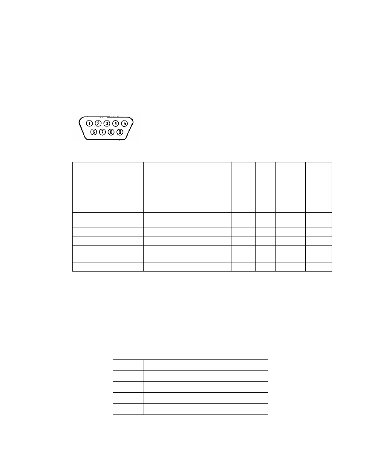
Helmholz Modem 56k small/Modem 56k USB small 87
14.2 PC Interface
14.2.1 Serial interface
(Only for HELMHOLZ Modem 56k small )
Layout of the 9-pin D-SUB jack
Description of the signals on the 9-pin D-SUB connector on DCE side:
9-pin D-
Sub DCE
Pin No.
Description
AT com-
mand
Function
CCITT
V-24
EIA
RS23
2
DIN
66020
E/A DCE
to DTE
1 DCD AT&C Data Carrier Detect 109 CF M5 O
2 RXD Receive Data 104 BB D2 O
3 TXD Transmit Data 103 BA D1 I
4 DTR AT&D
Data Terminal
Ready
108 CD S1 I
5 GND Ground 102 AB E2
6 DSR AT&S Data set ready 107 CC M1 O
7 RTS AT&R Request to send 105 CA S2 I
8 CTS AT&K Clear to send 106 CB M2 O
9 RI Ring Indication 125 CE M3 O
14.2.2 USB Interface
(Only for HELMHOLZ Modem 56k USB small)
Layout of the 4-pin USB jack, type B
Description of the signals:
Pin Name
1 USBVCC, USB supply voltage
2 D-, data line
3 D-, data line
4 GND, ground
Page 88
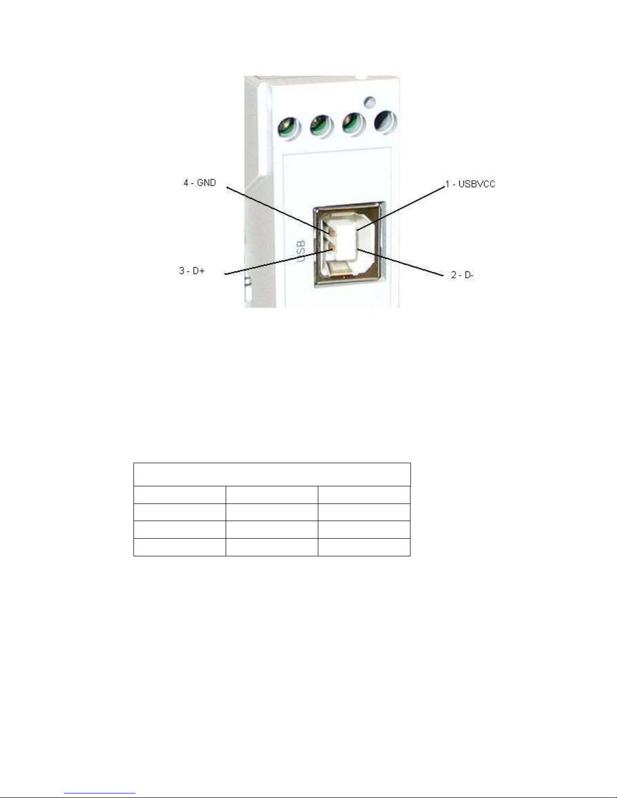
88 Helmholz Modem 56k small/Modem 56k USB small
14.3 Possible Interface Speeds
Baud rate in bps
300 4.800 28.800
600 9.600 38.400
1.200 14.400 57.600
2.400 19.200 115.200
Page 89
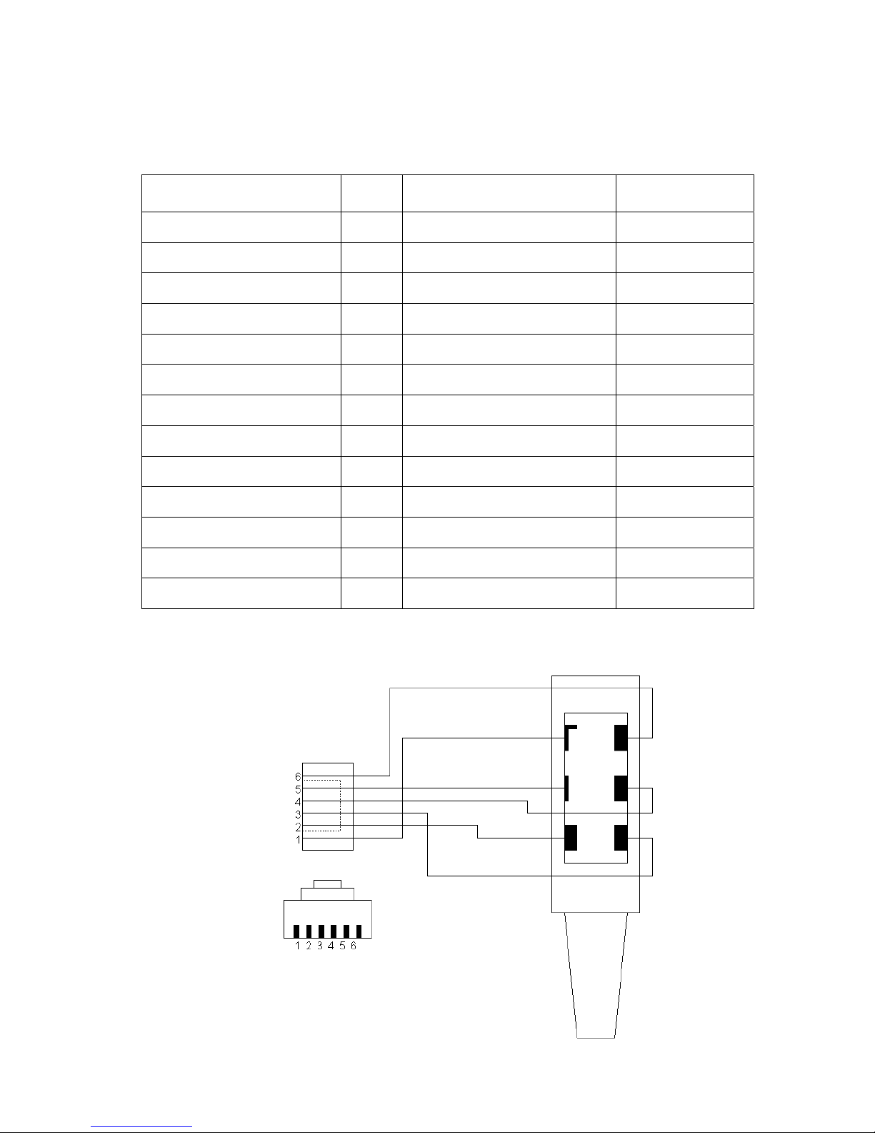
Helmholz Modem 56k small/Modem 56k USB small 89
14.4 Supported Transmission Standards
Transmission standard Transmission standard
V.17 9 V.44 Data Compression 9
V.21 9 V.90 9
V.21 Channel2 9 V.92 9
V.22A/B 9 Bell 212A and 103 9
V.22bis 9 Remote Maintenance 9
V.23 9 Fax group 3 send/receive up to 14,400 bps
V.27ter 9 Fax class 1 command set 9
V.29 9 Fax class 2 command set 9
V.32bis 9 MNP 2-4 error correction 9
V.34 9 MNP 5 Data Compression 9
V.34+ 9 MNP 10 error correction 9
V.42bis Data Compression 9 Security callback 9
V.42 LAPM error correction 9 Voice functions 9
14.5 Telephone Interface
RJ 12 connector directed
backwards
RJ 12 connector front
b2 b
1
a2
Page 90

90 Helmholz Modem 56k small/Modem 56k USB small
Layout of the RJ12 Connector and the RJ45 Jack
Pin Description Pin Description
1 NC 4 b1
2 a2 5 b2
3 a1 6 NC
Meaning of the Signals:
a1, b1: Incoming phone lines
(e.g. exchange connection or PBX)
a2, b2: They are used to connect a telephone in series. In idle state, a2 and b2 are
connected with a1 and b1 via a loop current connector. a2 and b2 are disconnected as soon as the modem occupies the line.
Page 91

Helmholz Modem 56k small/Modem 56k USB small 91
14.6 ITU Standards (CCITT)
ITU Standards
(CCITT)
Meaning
V.21
Transmission with 300 bps (duplex)
V.22
Transmission with 1,200 bps (duplex)
V.22bis*
Transmission with 2,400 bps (duplex)
V.23
Send with 75 bps and receive with 1,200 bps and vice versa.
V.23 half-duplex
Send and receive with 1,200 bps.
V.25bis*
Alternate command set for AT command set
V.32
Transmission with 9,600 bps or (fallback) 7,200, 4,800 bps.
V.32bis*
Transmission with 14,400 bps or (fallback) 12,000, 9,600, 7,200, 4,800
bps.
V.FC
Transmission with 28,800 bps or (fallback) 26,400, 24,000, 21,600,
19,200, 16,800, 14,400 bps.
V.34
Transmission with 28,800 bps or (fallback) 26,400, 24,000, 21,600,
19,200, 16,800, 14,400 bps.
V.34+
Transmission with 33,600 bps or (fallback) 31,200, 28,800, 26,400,
24,000, 21,600, 19,200, 16,800, 14,400 bps.
K56flex
Transmission with 56,000 bps or (fallback) 54,000, 52,000, 50,000,
48,000, 46,000, 44,000, 42,000, 40,000, 38,000, 36,000, 34,000, 32,000
bps.
V.42
Error protection method for DCE’s with asynchronous-to-synchronous
conversion
V.42bis*
Data compression method
V.90
Transmission with 56,000 bps or 54,667, 53,333, 52,000, 50,667, 49,333,
48,000, 46,667, 45,333, 42,667, 41,333, 40,000, 38,667, 37,333, 36,000,
34,667, 33,333, 32,000, 30,667, 29,333, 28,000 bps.
*bis = extended (french: secondly)
Bps indicates the transmitted bits per second.
Duplex means that the transmission takes place into both directions.
Page 92

92 Helmholz Modem 56k small/Modem 56k USB small
15 Country Codes
Adjust the modem to local requirements using the command
AT+GCI=<countrycode>
All other settings should be carried out after
the country code has been
selected, because some factory settings depend on the country.
HELMHOLZ Modem 56k small
Country
Standard coun-
tries
Extended
country groups
TBR21*) FD (default) FD (default)
Egypt 38
Albania B8
Algeria FE
Andorra FD FD
Argentina 07
Australia 09
Algeria FE
Bangladesh FE
Belgium* FD/0F FD
Birma (Myanmar) FE
Brazil 16
Bolivia FE
Bosnia Herzegovina FE
Brunei FE
Bulgaria 1B
Chile 25
China 26
Costa Rica FE
Denmark* FD/31
Germany FD/42
Dominican Republic 33
Ecuador FE
El Salvador FE
Estonia F9
Finland* FD/3C FD
France* FD/3D FD
Greece* FD/46 FD
Great Britain* FD/B4 FD
Guatemala FE
Honduras FE
Hong Kong 50
Page 93

Helmholz Modem 56k small/Modem 56k USB small 93
HELMHOLZ Modem 56k small
Country
Standard coun-
tries
Extended
country groups
India 53
Indonesia 54
Ireland* FD/57 FD
Iceland* FD/52 FD
Israel 58
Italy* FD/59 FD
ITU/Taiwan FE
Japan 00
Yemen FE
Jordan FE
Cambodia FE
Canada 20
Colombia 27
Republic of Korea 61
Croatia FA
Kuwait 62
Laos FE
Latvia FD FD
Lebanon 64
Liechtenstein* FD FD
Lithuania FE
Luxembourg* FD/69
Malaysia 6C
Macedonia FE
Mexico 73
Monaco FD FD
Montenegro FE
New Zealand 7E
Nicaragua FE
Netherlands* FD/7B FD
Nigeria 81
Norway* FD/82
Oman FE
Austria* FD/0A FD
Pakistan 84
Panama 85
Paraguay 87
Peru FE
Philippines 89
Poland 8A
Portugal* FD/8B FD
Page 94

94 Helmholz Modem 56k small/Modem 56k USB small
HELMHOLZ Modem 56k small
Country
Standard coun-
tries
Extended
country groups
Romania 8E
Russian Federation B8
San Marino* FD FD
Saudi Arabia 98
Sweden* FD/A5 FD
Switzerland FD/A6* FD
Senegal 99
Serbia FE
Singapore 9C
Slovak Republic FB
Slovenia FC
Spain* FD/A0
Sri Lanka A1
South Africa 9F
Taiwan FE
Thailand A9
Czech Republic 2E
Turkey AE
Tunisia FE
Ukraine FE
Hungary 51
Uruguay B7
USA B5
Venezuela BB
United Arab Emirates B3
Belarus FE
Cyprus 2D
*) The standard TBR21 applies to all public phone networks in EU countries (Bel-
gium, Denmark, German, Finland, France, Greece, Great Britain, Ireland, Italy,
Luxembourg, Netherlands, Austria, Portugal, Sweden, Spain), as well as in Switzerland, Liechtenstein, Norway and Iceland. Only old telecommunications systems require the individual country to be set explicitly.
Page 95

95
 Loading...