

Page 1
www.helmholz.de
Version
2
en
ab FW 1.02
Quick Start Guide
PN/CAN Gateway Layer 2
Page 2

Quick Start Guide PN/CAN Gateway Layer 2
2
Content
1. Introduction 3
2. Preparation of the PN/CAN Gateway 3
3. Congure PN/CAN Gateway 4
4. PN/CAN Gateway settings 5
5. Adding CAN frame 6
6. Assign the PN/CAN Gateway a PROFINET name 11
7. Programming in the PLC 12
8. LED status information 16
9. Technical data 17
Page 3
Quick Start Guide PN/CAN Gateway Layer 2
3
2. Preparation of the PN/CAN Gateway
2.1 Connection
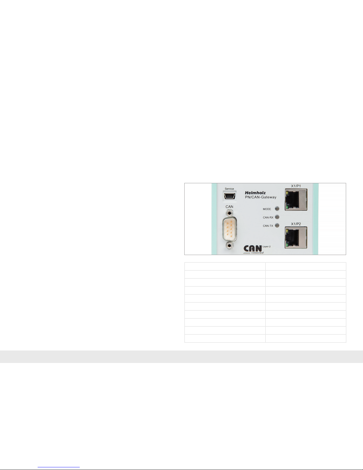
The PN/CAN Gateway is supplied via the 3-pin connection plugs with 24 V DC
voltage.
The CAN bus is connected to the „CAN“ interface using a SUB-D plug (e.g. Helmholz
CAN bus plug).
The PROFINET line is connected to X1/P1 or X1/P2.
The service USB interface is required for the rmware update and for diagnoses in
the event of support.
1. Introduction
Before getting started:
Please observe the safety instructions for the product, which can be found in the ma-
nual. You can nd the manual on the accompanying CD or it can be downloaded from
the website www.helmholz.de in the download area.
This document should present the initial commissioning of the PN/CAN Gateway
with a simple CAN Device.
Pin SUB-D plug CAN-Bus
1 –
2 CAN Low
3 CAN GND
4 –
5 –
6 –
7 CAN High
8 –
9 –
Page 4
Quick Start Guide PN/CAN Gateway Layer 2
4
3. Congure PN/CAN Gateway
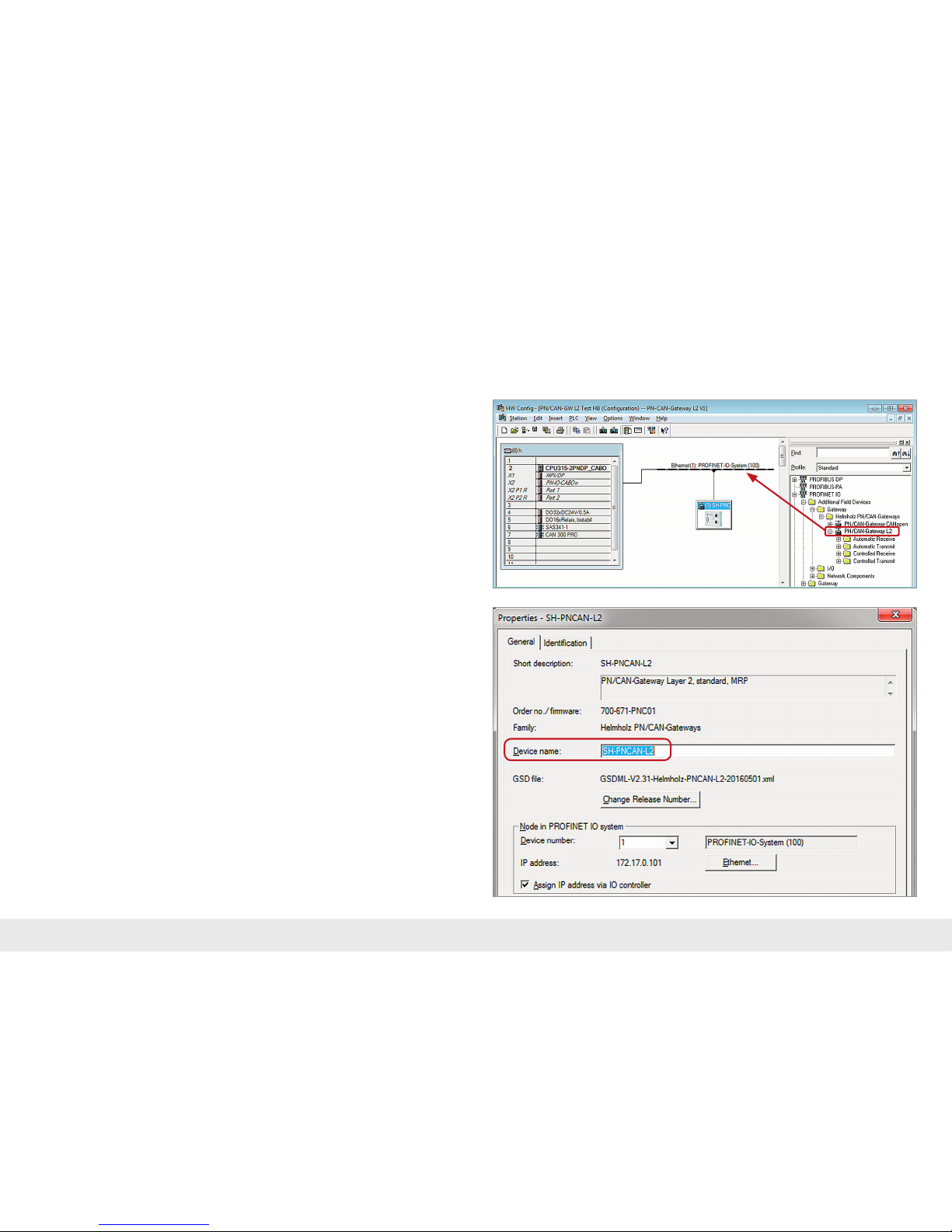
After installing the GSDML le, the PN/CAN Gateway Layer 2 can be found in the
hardware catalog under
„PROFINET IO -> Other eld devices -> Gateway -> Helmholz PN/CAN Gateways“.
Add the „PN/CAN Gateway L2“ to the project and connect it with your PROFINET
network.
By calling up the object properties, you can assign the PN/CAN Gateway a unique
PROFINET name and check the IP address for plausibility.
2.2 Install GSDML le
The GSDML le can be found on the accompanying CD or in the download area of
the PN/CANGateway at www.helmholz.com.
Page 5
Quick Start Guide PN/CAN Gateway Layer 2
5
4. PN/CAN Gateway settings
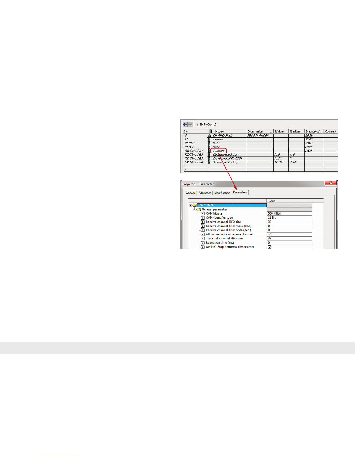
The rst slot entry after the ports is the slot for the parameters.
Set the CAN bit rate and the type of CAN identier (11 bit or 29 bit). The importance
of the additional parameters can be derived from the manual and have no relevance
for standard applications.
The other „PN/CAN L2“ slot modules contain no parameters.
Page 6
Quick Start Guide PN/CAN Gateway Layer 2
6
5. Adding CAN frame
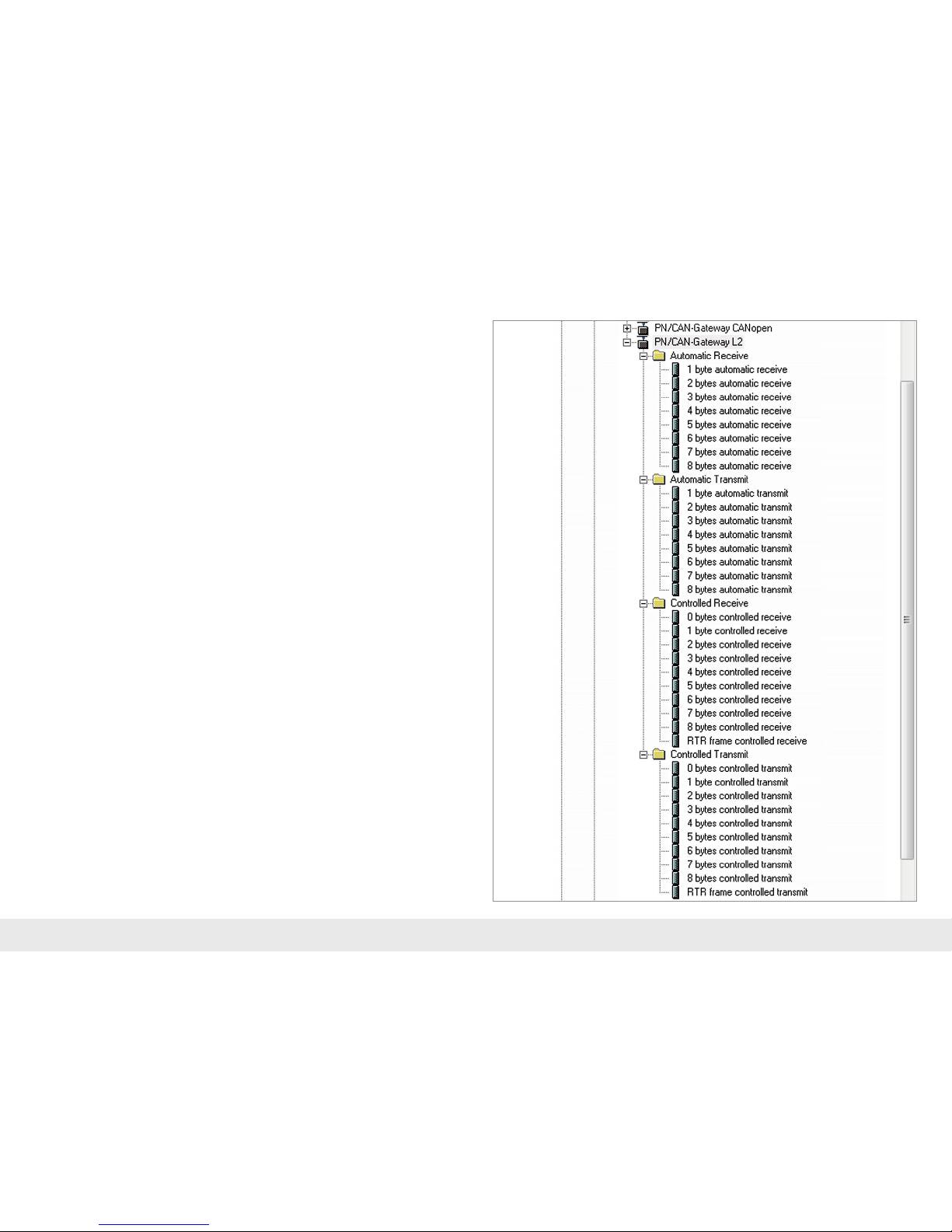
The PN/CAN Gateway Layer 2 can transmit and receive CAN frames with 1 to 8 bytes
of data and any CAN-IDs. A module with the CAN identier must be congured in
the slots of the PN/CAN Gateway for each anticipated CAN frame and each CAN
frame to be transmitted.
There are two types of CAN frames: automatic receiving/transmission and con-
trolled receiving/transmission.
In the case of the automatic reception of CAN frames, the data of the most recently
received CAN frame is always found in the input data. If a CAN frame with identical
data is received several times, this can‘t be recognized in the PLC.
In the case of automatic transmission the CAN frame is transmitted as soon as
something changes in the output data of the frame. Repeat transmission of the same
data is thus not possible.
In the case of controlled reception and the controlled transmission of CAN frames,
the PLC program has direct control over each telegram through control and status
bits.
Page 7
Quick Start Guide PN/CAN Gateway Layer 2
7
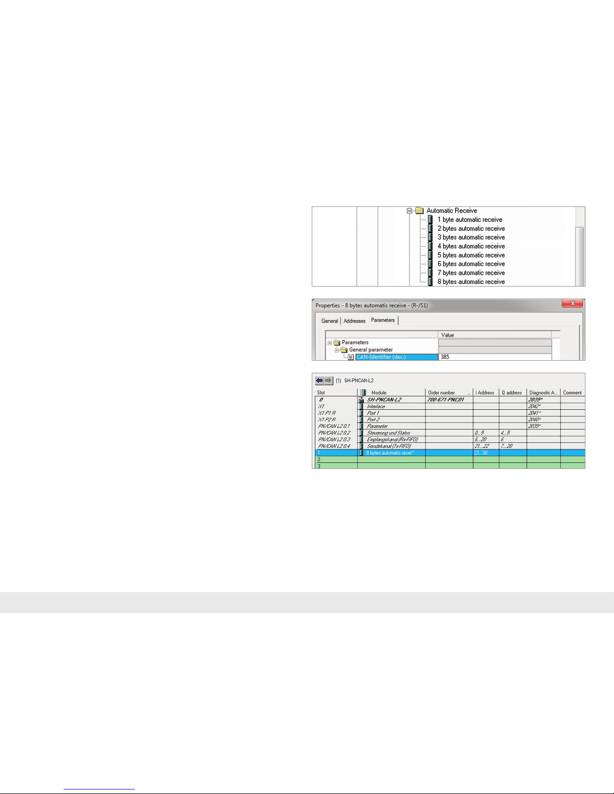
Each congured CAN frame has a unique CAN identier. If two reception objects
with the same CAN identier are being congured, that results in a conguration
error.
5.1 Automatically receiving CAN frames
In the case of the automatic reception of CAN frames, the data of the most recently
received CAN frame is always found in the input data.
A CAN frame always has a xed data length. In the case of automatic reception, CAN
frames with a xed data length of 1 to 8 bytes can be congured.
If a CAN frame is received that has the correct CAN identier but a false data length,
the frame is rejected and the data is not forwarded to the PLC!
CAN frames with differing data lengths can be processed with the receiving channel
(Rx-FIFO).
Page 8
Quick Start Guide PN/CAN Gateway Layer 2
8
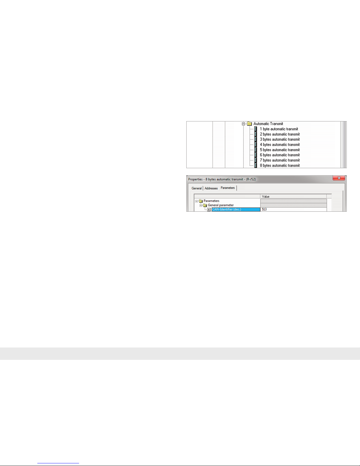
Each congured CAN frame has a unique CAN identier. If two transmission objects
with the same CAN identier are being congured, that results in a conguration
error.
5.2 Automatically transmitting CAN frames
In the case of automatic transmission of a CAN frame, a frame is always sent to the
CAN bus when the output data of the module changes.
In the case of automatic transmission, CAN frames with a xed data length of 1 to
8 bytes can be congured. The transmission of CAN frames with a variety of data
lengths can be carried out with the transmission channel (Tx-FIFO).
Page 9
Quick Start Guide PN/CAN Gateway Layer 2
9
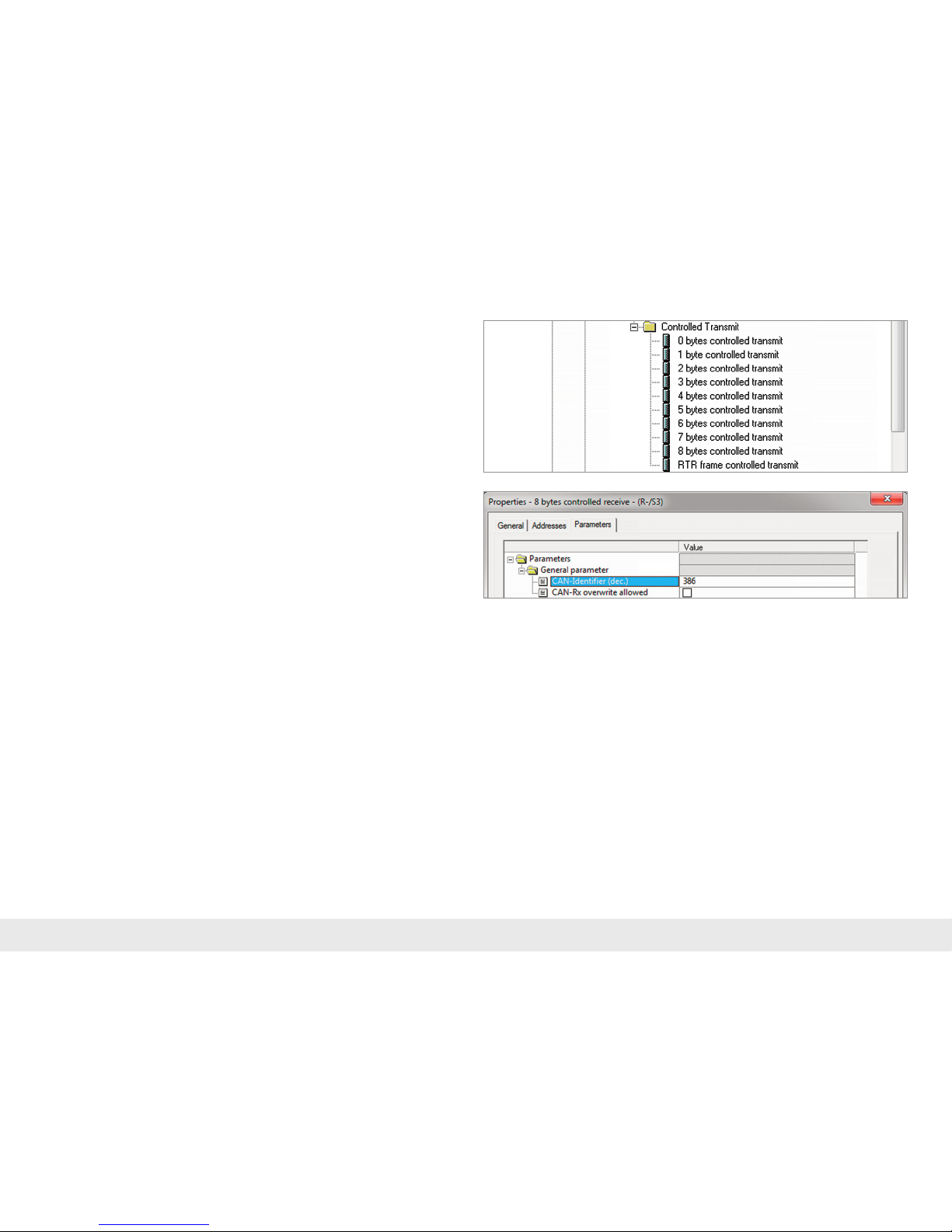
In the case of controlled reception, CAN frames with a xed data length of 0 to 8
bytes can be congured. An RTR frame can also be received.
If a CAN frame is received that has the correct CAN identier but a false data length,
the frame is rejected and the data is not forwarded to the PLC!
5.3 Controlled receiving of CAN frames
In the case of the controlled reception of CAN frames, the reception of each frame
must be acknowledged in the PLC program.
If two reception objects with the same CAN identier are being congured, that
results in a conguration error.
Page 10
Quick Start Guide PN/CAN Gateway Layer 2
10
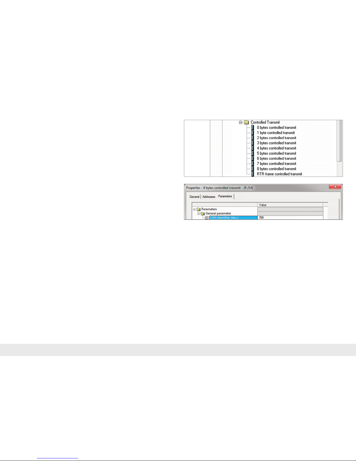
In the case of controlled transmission, CAN frames with a xed data length of 0 to 8
bytes can be congured. An RTR frame can also be transmitted.
5.4 Controlled transmission of CAN frames
In the case of controlled transmission of a CAN frame, the PLC can directly trigger
the transmission of a CAN frame through a control bit, irrespective of whether the
transmission data has changed.
If two reception objects with the same CAN identier are being congured, that
results in a conguration error.
Page 11
Quick Start Guide PN/CAN Gateway Layer 2
11
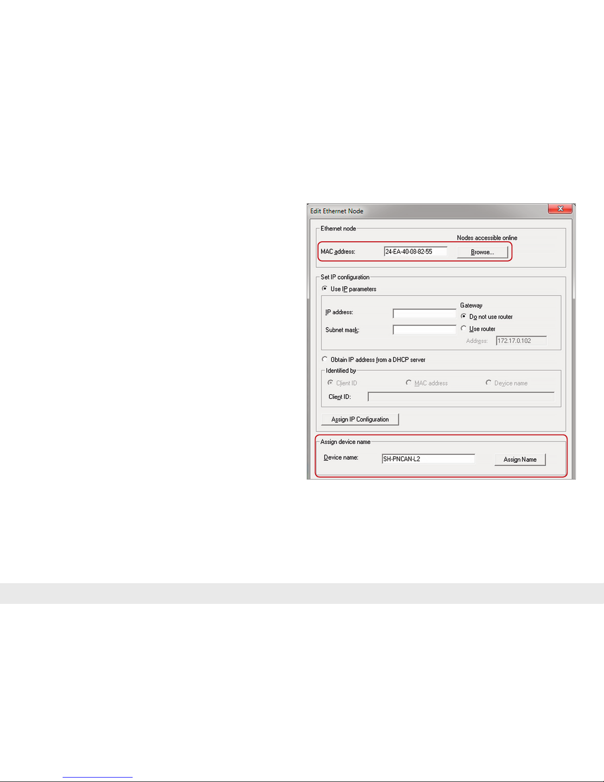
6. Assign the PN/CAN Gateway a PROFINET name
When the conguration of the PN/CAN Gateway has been completed in the hardware congurator, it can be loaded into the PLC.
In order that the PN/CAN Gateway can be found on the PROFINET by the PROFINET
master (controller), the PROFINET name and possibly the IP address must be set.
To this purpose the function „Edit Ethernet Node“ is used in the SIMATIC
1
manager.
With the „Browse…“ button, the network can be browsed for PROFINET devices.
The clear identication of the PN/CAN Gateway is ensured here by the MAC address
of the device.
Important: The assigned name must agree with the name dened in the hardware
congurator.
If the PN/CAN Gateway contains the correct PROFINET name, it is recognized by the
PLC and congured.
When the conguration has run correctly, the blue „Mode“ LED should blink.
Page 12

Quick Start Guide PN/CAN Gateway Layer 2
12
7. Programming in the PLC
No handling blocks for simple operation are required in the PLC. The control and
status query of the PN/CAN Gateway can be carried out directly via the I/O map.
In order to start up the example project, the value 3 must be written into the „Control“ output word in order to switch to normal operation.
7.1 Control (2 bytes outputs)
The mode bits are used for the status control of the PN/CAN Gateway.
INIT (0) = CAN controller is at the bus, no frames are transmitted, received frames
are discarded; outputs/inputs are set to zero; FIFOs are deleted.
The INIT (0) status is automatically active in the event of a PROFINET network cancellation or stoppage of the PLC.
PASSIV (1) = CAN Controller is at the bus; received frames are discarded, no frames
are transmitted; error counters are transmitted to the PLC; FIFOs are maintained and
can be operated; Rx-FIFO can be read until it is empty; Tx-FIFO can be described, but
no frames are transmitted; controlled transmission modules can be operated; data
from automatic receiver modules remain frozen
RX-Only (2) = Only the CAN reception is processed. No CAN frames are transmitted.
RX-TX (3) = Normal operation with transmitter and receiver.
Note: In order to switch to normal operation, it is permitted to switch directly from mode
0 to mode 3. All necessary initializations (mode 1) will thereby take place automatically.
Byte/Bit 7 6 5 4 3 2 1 0
Out 0 – Reset – – – – – –
Out 1 – – – – – – Mode
Page 13

Quick Start Guide PN/CAN Gateway Layer 2
13
7.2 Status (6 bytes inputs)
The two mode state bits show the status of the PN/CAN Gateway. Principally, an
attempt is made to occupy the status required in the mode of the control word.
However, this can be prevented by conguration errors.
INIT (0) = CAN controller is at the bus, no frames are transmitted, received frames
are discarded; outputs/inputs are set to zero; FIFOs are deleted.
PASSIV (1) = CAN controller is at the bus; received frames are discarded, no frames
are transmitted; error counters are transmitted to the PLC; FIFOs are maintained and
can be operated; Rx-FIFO can be read until it is empty; Tx-FIFO can be described, but
no frames are transmitted; data from automatic receiver modules remain frozen.
RX-Only (2) = Only the CAN reception is processed. No CAN frames are transmitted.
RX-TX (3) = Normal operation with transmitter and receiver.
Byte/Bit 7 6 5 4 3 2 1 0
In 0 1= Gateway
ready
1 = Reset carried
out
– – – – – –
In 1 Error code for conguration errors - - Mode State
In 2 CAN receive error counter
In 3 CAN transmit error counter
In 4+5 First slot with conguration error
Error code for conguration errors
1: Pluggable objects: Dual CAN-ID assignment
3: Reception channel FIFO: Filter mask and lter code results in too many lter
entries (max. 16)
4: Filter table CAN hardware lter is full
5: General conguration errors
6: The rmware doesn‘t support a congured module -> Firmware update
required
First slot with conguration error
In connection with the error code for conguration errors, this value indicates the
plug point of the rst module with a conguration error.
CAN receive error counter: Error counter of the CAN controller
CAN transmit error counter: Error counter of the CAN controller
Page 14
Quick Start Guide PN/CAN Gateway Layer 2
14
7.3 Controlled receiving of CAN frames
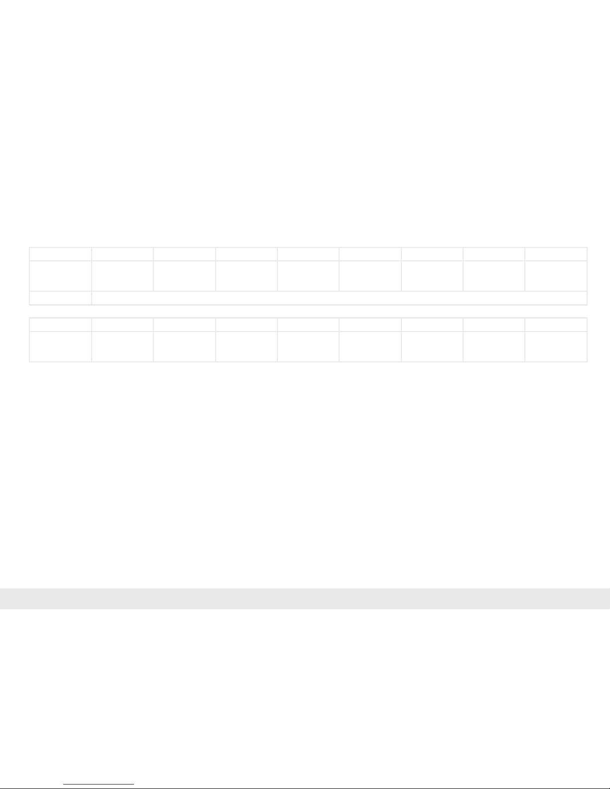
In the PLC, every controlled reception object has a status and a control byte in addition to the CAN data:
The indication and the acknowledge bit for the reception of new CAN frames are
always toggled:
- Indication bit = Acknowledge bit -> no new frame received
- Indication bit ≠ Acknowledge bit -> a new frame has been received
In order to be able to receive the next frame, the acknowledge bit must simply set
equally to the indication bit.
Byte/Bit 7 6 5 4 3 2 1 0
In 0 – – – – – – 1 = Overrun Indication
toggle bit of
new frame
In 1–n CAN frame data depending upon the selected frame length (0 - 8 bytes)
Byte/Bit 7 6 5 4 3 2 1 0
Out 0 – – – – – – Overrun-Reset Acknowledge
toggle bit of
new frame
Page 15

Quick Start Guide PN/CAN Gateway Layer 2
15
7.4 Controlled transmission of CAN frames
In the PLC, every controlled transmission object has a status and a control byte in
addition to the CAN data:
The request and the acknowledge bit for the transmission of CAN frames are always
toggled:
- Request bit ≠ Acknowledge bit -> Transmit frame
- Request bit = Acknowledge bit -> Don‘t transmit frame
7.5 Reception channel (Rx-FIFO)
The reception channel FIFO object can be used for the reception of a range of CAN
frames that can also have differing data lengths. The PN/CAN Gateway hereby also
provides a FIFO buffer with adjustable size.
Details on the use of the reception channel can be found in the manual of the PN/
CAN Gateway.
Byte/Bit 7 6 5 4 3 2 1 0
In 0 – – – – – – – Transmit
Acknowledge
7.6 Transmission channel (Tx-FIFO)
Any number of CAN frames can be sent with the transmission channel FIFO. Both the
CAN identier and the data length can be selected as desired. It is also possible to
transmit CAN frames with identiers that have already been congured as automatic
or controlled modules.
Details on the use of the transmission channel can be found in the manual of the
PN/CAN Gateway.
Byte/Bit 7 6 5 4 3 2 1 0
Out 0 – – – – – – – Request transmit
Out 1–n CAN frame data depending upon the selected frame length (0 - 8 bytes)
Page 16

Quick Start Guide PN/CAN Gateway Layer 2
16
MODE
Off No power supply or device defective
Blue on PN/CAN Gateway is correctly congured via PROFINET
Mode 3: Transmitting and receiving active
Flashing blue PN/CAN Gateway is correctly congured via PROFINET
Mode 0, 1 or 2
Flashing red No connection with PROFINET controller (PLC) or a con-
guration error exists
CAN-RX
Flashing green CAN frame is received without errors
Red CAN bus error in the recipient or PN/CAN Gateway hasn‘t
been congured yet
CAN-TX
Flashing green CAN frames are being transmitted
Rot Transmission not possible (e.g. false Baud rate, CAN bus
disrupted) or PN/CAN Gateway has not yet been congured
8. LED status information
Page 17

Quick Start Guide PN/CAN Gateway Layer 2
17
Order no. 700-671-PNC01
PROFINET Interface
- Protocol PROFINET IO as dened in IEC 61158-6-10
- Transmission rate 100 Mbit/s full duplex
- I/O image size 1440 bytes
- Number of congurable slots 512
- Connection 2 x RJ45, integrated switch
- Features Media Redundancy Protocol (MRP), automatic addressing / topology detection (LLDP, DCP), diagnosis alarm
CAN interface
- Type ISO/DIN 11898-2 CAN High Speed physical Layer
- Connection 9-pin D-sub male connector
- Protocol CAN Layer 2 with 11-Bit or 29-Bit identier
- Baud rate 50, 100, 125, 250, 500, 800, 1000 kbps
USB interface
- Protocol USB 2.0 Device, Full Speed
- Connection Mini-USB
- Electrically isolated from USB Yes; Isolation 1.5 kV
Voltage supply DC 24 V, 18 - 28 V DC
Current draw Max. 250 mA
Dimensions (D x W x H) 35 x 84 x 76 mm
Weight Approx. 160 g
Certications CE
Protection ratings IP 20
Permissible ambient temperature 0 °C to +60 °C
Transport and storage temperature -20 °C to +80 °C
9. Technical data
Page 18

Quick Start Guide PN/CAN Gateway Layer 2
18
Notes
Page 19

Quick Start Guide PN/CAN Gateway Layer 2
19
Notes
Page 20

Note
The contents of this Quick Start Guide have been checked by us so as to ensure that they match the hardware and software described. However, we assume no liability for any existing
differences, as these cannot be fully ruled out.
The information in this Quick Start Guide is, however, updated on a regular basis. When using your purchased products, please make sure to use the latest version of this Quick Start
Guide, which can be viewed and downloaded on the Internet at www.helmholz.com.
Our customers are important to us. We are pleased to receive suggestions for improvement and new impulses.
1) SIMATIC is a registered trademark of Siemens AG.
Helmholz GmbH & Co. KG | Hannberger Weg 2 | 91091 Großenseebach | Germany | Phone +49 9135 7380-0 | Fax +49 9135 7380-110 | [email protected] | www.helmholz.de
 Loading...