

Page 1

Helm Instrument Company, Inc.
PTM - 1100
USER MANUAL
REV. 1
JUNE 2010
361 West Dussel Drive
Maumee, Ohio 43537 USA
419/ 893-4356
Fax: 419/ 893-1371
www.helminstrument.com
HELM INSTRUMENT CO., INC.
1
Page 2

LIMITED WARRANTY
Helm Instrument Co., Inc. (”HELM”) hereby warrants that the instruments and sensors
(collectively the ”Product”) manufactured by it and sold to customer, are free from
defects in material and/or workmanship under normal use subject to the following
conditions. This warranty shall not apply to any Product which has been subjected to
improper installation, misuse, negligence, accident, alteration, where service has been
performed by other than an authorized Helm serviceman, or where the serial number
has been defaced or altered. This warranty shall extend for the one (1) year period from
date of shipment from our factory or authorized dealer, provided that the product is
returned, freight prepaid, to Helm within the one (1) year warranty period within specific
written authorization to perform repairs. Helm’s obligations and the exclusive remedy of
customer under this warranty are limited to repairing or replacing any defective Product
at no additional charge and returning Product to customer freight paid. Repair parts and
replacement Products shall be furnished on an exchange basis and shall be either new
or reconditioned. All replaced parts and Products shall become the property of Helm.
EXCEPT AS SPECIFICALLY STATED HEREIN, HELM MAKES NO WARRANTIES
EXPRESSED OF IMPLIED, OF THIS PRODUCT INCLUDING BUT NO LIMITED TO
WARRANTIES OF MERCHANTABILITY OR FITNESS FOR A PARTICULAR
PURPOSE, OR AS TO THE QUALITY, UTILITY OR PERFORMANCE, ALL QF W HICH
ARE HEREBY EXPRESSLY EXCLUDED. IN NO EVENT SHALL THE LIABILITY OF
HELM EXCEED THE PURCHASE PRICE OF THIS PRODUCT. NOR SHALL HELM BE
LIABLE FOR ANY DAMAGES WHATSOEVER, INCLUDING BUT NOT LIMITED TO
SPECIAL, INDIRECT, INCIDENTAL OR CONSEQUENTIAL CHARGES, EXPENSE OR
DAMAGES, ARISING OUT OF THE USE OR INABILITY TO USE THIS PRODUCT OR
FOR ANY CLAIM BY ANY OTHER PARTY.
Should you have any questions concerning this Warranty, you may contact Helm by
writing or calling:
HELM INSTRUMENT COMPANY, INC.
CUSTOMER SERVICE
361 WEST DUSSEL DRIVE
MAUMEE, OHIO 43537
(419) 893-4356
i
Page 3

INTRODUCTION........................................................................................................................................................2
ABOUT PTM-1100 SERIES.......................................................................................................................................2
BENEFIT.......................................................................................................................................................2
PTM (PEAK TONNAGE MODULE)..............................................................................................................2
MAIN FEATURES.........................................................................................................................................2
OPERATING MODES...................................................................................................................................2
ALARMS .......................................................................................................................................................2
OTHER FEATURES .....................................................................................................................................3
USER CONNECTIONS..............................................................................................................................................3
CUSTOMER SUPPLIED POWER................................................................................................................3
CAM INPUT ..................................................................................................................................................3
HIGH/LOW CAPACITY FAULT RELAY OUTPUT........................................................................................3
STRAIN GAGE INPUT..................................................................................................................................3
TOUCH SCREEN INTERFACE.................................................................................................................................4
MAIN MENU..................................................................................................................................................4
SETUP SCREEN..........................................................................................................................................5
JOB RECIPE SCREEN.................................................................................................................................6
PTM MODULE...........................................................................................................................................................7
STRAIN GAGE SENSOR INPUT .................................................................................................................7
INITIAL SET-UP AND CALIBRATION..........................................................................................................7
PTM MODULE DRAWING:........................................................................................................................................9
PTM MODULE WIRING:..........................................................................................................................................10
PTM MODULE SIGNAL DIAGRAM:........................................................................................................................11
PTM-1100 USER CONNECTIONS:.........................................................................................................................12
1
Page 4

PTM-1100 Operators Manual
INTRODUCTION
HELM INSTRUMENT CO., INC. manufactures a complete line of load monitoring control systems
for use on metal stamping, forging, compaction and assembly presses; cold forming, cold
heading, injection molding and die cast machines. Standard or custom transducers and load cells
are available for in-die monitoring and transfer or progressive tooling. At HELM, quality is
inherent not only in the design of our products but in the attitudes of our employees as well.
We're working together to give you the best. After all, that's what our business is all about providing innovative instrumentation to help make your manufacturing process more productive
and your operation more effective.
ABOUT PTM-1100 SERIES
BENEFIT
• Press Protection – protect press components, including dies, from costly damage
• Parts Quality Control – ensure parts are being made (stamped) as specified
PTM (PEAK TONNAGE MODULE)
• PTM is a single channel strain gage sensor input module to process the signal of the strain
gage to analog output.
• PTM provides Auto-Zero® feature (patented by Helm Instrument Co., Inc.). The Auto-Zero®
feature automatically keeps the zero balance of the load signal between every load cycles to
compensate the tonnage variation affected by any environmental conditions changes such as
temperature.
MAIN FEATURES
OPERATING MODES
PTM-1100 has two function modes controlled by an operator.
• Calibrate Mode – Used for system setup or Job setup, capacity alarms are active, but
relay output is disabled. Calibrate mode will automatically be turned back
to peak after 5 minutes, incase accidently left in calibrate.
• Peak Mode – Used after calibration is complete for standard tonnage monitoring
operations. Capacity alarms and relays are active.
ALARMS
In normal operation, the Alarm relay is closed for fail safe. When the tonnage alarm(s)
condition is detected, the system opens the TOP STOP relay
• High/Low Capacity – Normally set at machine capacity. This provides the protection for
the Machine. This alarm is active in all modes.
.
2
Page 5

PTM-1100 Operators Manual
OTHER FEATURES
• Jobs Recipe – You create alarm settings per job base and store to Job Recipe for later
quick download to setup the system.
• Password Protection – The setup screen is password protected to insure only
appropriate personnel can bypass the alarms (switch to calibrate more) or change the
scale set point.
USER CONNECTIONS
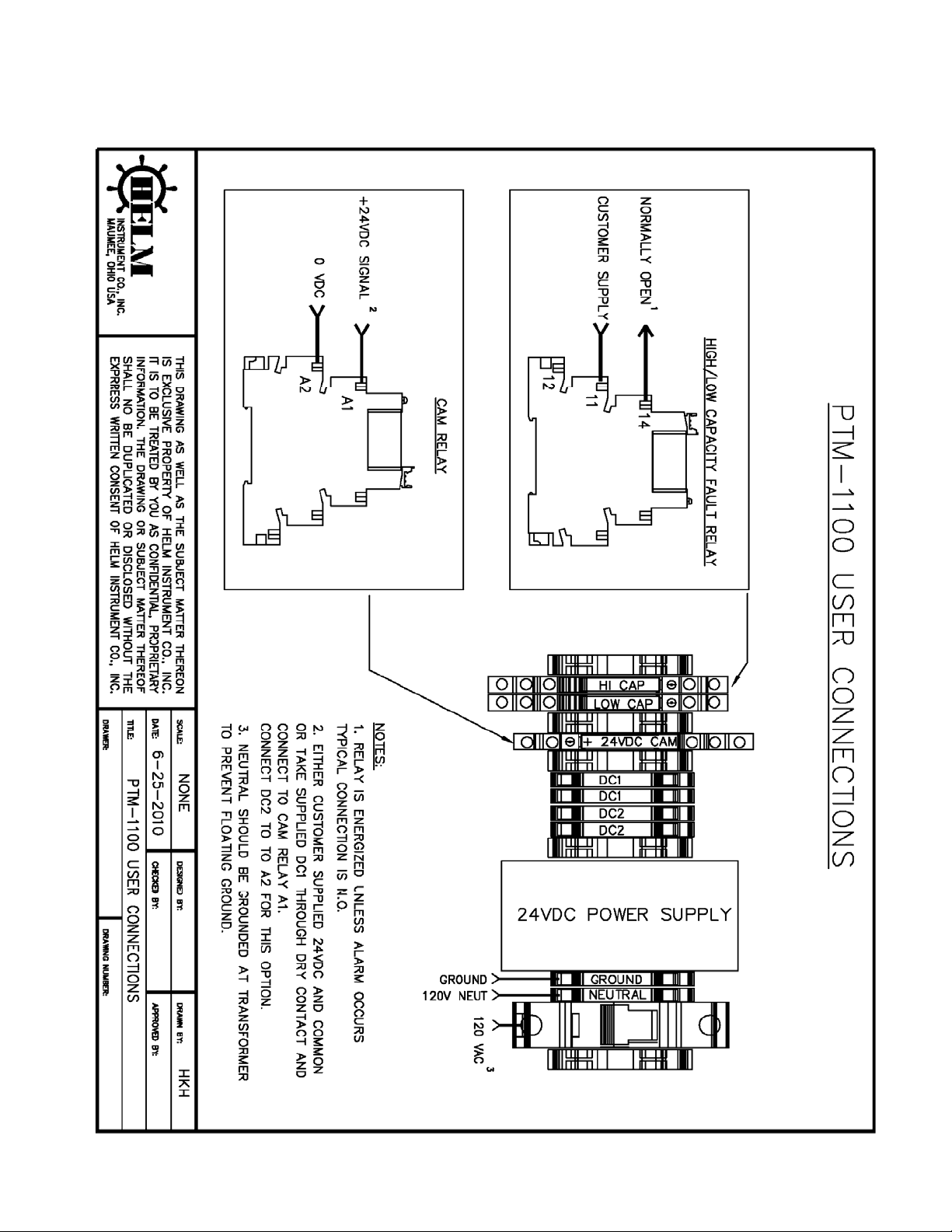
Refer to page 12 for the user connections drawing.
CUSTOMER SUPPLIED POWER
A Precut hole has been provided to connect conduit for customer supplied power.
• 120VAC – Connect to the 3Amp Circuit Breaker
• AC Neutral – Connect to the Neutral Terminal. (Neutral should be grounded at the
transformer to prevent floating ground)
• GND – Connect to Ground.
CAM INPUT
The provided CAM INPUT relay is a 24VDC relay, and can either be triggered by customer
provided +24VDC and DC common, or Use the supplied DC1 (+24VDC) through a dry contact to
A1 and connect DC2 (0VDC) to A2. This input can be triggered with a proximity switch or a PLC
output. This input is the “look window” for the tonnage monitor.
• A1 – +24VDC signal.
• A2 – 0VDC signal.
HIGH/LOW CAPACITY FAULT RELAY OUTPUT
The provided relay output is programmed to be energized unless a fault occurs; this is considered
“Fail Safe”. If a relay output turns off, a fault has occurred, and will commonly trigger a top stop.
• 11 – Customer supplied Signal
• 12 – Normally Closed Output, this is the typical not used.
• 14 – Normally Open Output, this is the typical connection point for an alarm signal, and is
commonly connected with the presses TOP STOP circuit.
STRAIN GAGE INPUT
The drawing on page 10 shows the proper wiring for a strain gage to the PTM. The strain gage
wiring should not be ran within 12” of any high voltage, (60V or above), if necessary wires
should cross perpendicular to insure the least amount of noise transference.
3
Page 6
PTM-1100 Operators Manual
TOUCH SCREEN INTERFACE
MAIN MENU
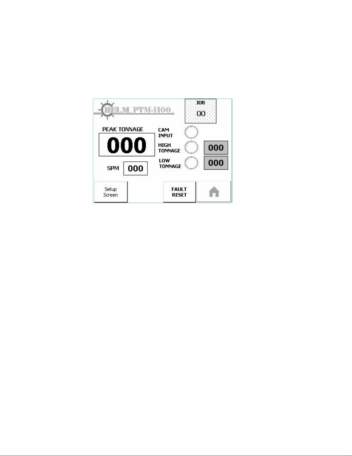
Main menu allows you to access different area of the system. The PTM-1100™ features a
touch screen display for easy navigation and operation of the system. Click or touch on the
button you wish to access.
JOB – Displays the current job. Press to go to job screen.
PEAK TONNAGE – Displays the peak tonnage value.
CAM INPUT – Pilot is set when Cam input is on (high).
HIGH TONNAGE – Displays the current High Capacity Alarm Set point. Pilot is set when
there is a High tonnage alarm. Pilot can be set and relay is off, if in calibrate mode.
LOW TONNAGE – Displays the current Low Capacity Alarm Set point. Pilot is set when there
is a Low tonnage alarm. Pilot can be set and relay is off, if in calibrate mode.
SPM – Displays the current Strokes Per Minute, which is calculated based on the duration of
time between cam pulses.
HOME – This button is inactive on the main screen, but will return the user to the main
screen when pressed.
FAULT RESET – This button will clear all displayed faults and fault relay outputs.
SETUP SCREEN – Pressing this will prompt the user for the Setup Password. By pressing
the 0-9 number button the user can navigate to the keypad and enter the numeric password.
Once entered, press the Enter (Carriage Return, in lower right corner). Then press OK and
press the setup screen button again. The password privileges will automatically reset after 5
minutes of screen inactivity.
4
Page 7
PTM-1100 Operators Manual
SETUP SCREEN
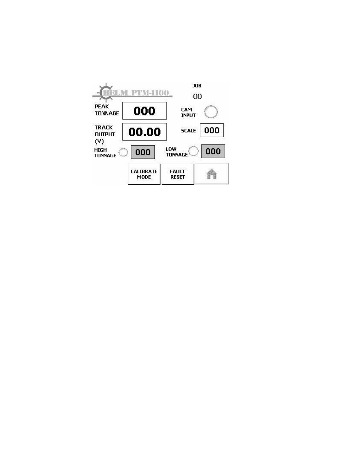
This screen is used to calibrate the system and set the scale value, this screen is password
protected. Password is 361.
JOB – This displays the current loaded job.
PEAK TONNAGE – Displays the peak tonnage value.
CAM INPUT – Pilot is set when Cam input is on (high).
TRACK OUTPUT (V) – Displays the track output voltage, this can be used to reset the cal
value if needed. This should not be used for Zero balance, as it cannot display negative
numbers.
SCALE – Set for the capacity of the press.
HIGH TONNAGE – Displays the current High Capacity Alarm Set point. Pilot is set when
there is a High tonnage alarm. Pilot can be set and relay is off, if in calibrate mode.
LOW TONNAGE – Displays the current Low Capacity Alarm Set point. Pilot is set when there
is a Low tonnage alarm. Pilot can be set and relay is off, if in calibrate mode.
HOME – Press to return to the main screen.
FAULT RESET – Press to clear all displayed faults and fault relay outputs.
CALIBRATE/PEAK MODE – This button will clear toggle the unit between pea k and calibrate
modes. (In calibrate mode capacity alarm relay outputs are bypassed). The system will
automatically switch back to peak mode after 5 minutes.
5
Page 8
PTM-1100 Operators Manual
JOB RECIPE SCREEN
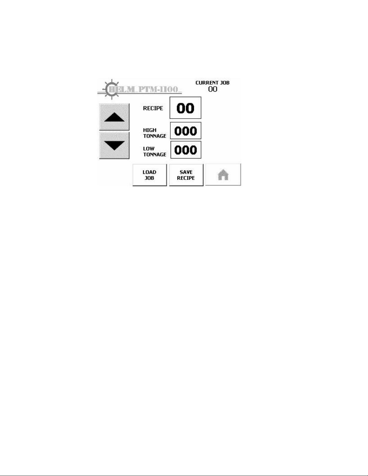
This screen displays the high and low tonnage set points for each job recipe, and allows you to
set, save, and load jobs.
CURRENT JOB – Displays the current job.
RECIPE – Displays the recipe selected, if pressed you can type the desired re cipe (1-20).
UP ARROW – Used to move to higher value recipe.
DOWN ARROW – Used to move to lower value recipe.
HIGH TONNAGE – Press to set the recipe High Capacity Alarm Set point.
LOW TONNAGE – Press to set the recipe Low Capacity Alarm Set point.
HOME – Press to return to the main screen.
SAVE RECIPE – Press to save the displayed settings to the selected recipe.
LOAD JOB – Press to load the selected recipe into the system.
6
Main Tonnage screen from PTM-6700TSM-R
Page 9

PTM-1100 Operators Manual
PTM MODULE
STRAIN GAGE SENSOR INPUT
The strain gage sensor wires are connected at the green 5-pole
Weidmuller connector at the bottom of the module. Connections include
“+ Gage”, “+ Signal”, and “Shield”. For ease of wiring at the
connector, it can be removed from the module while making the 5 connections at the
screw terminals.
INITIAL SET-UP AND CALIBRATION
Zero Balance
After the proper wiring connections are made, the module should be set up by conne cting a
good quality voltmeter to the 0-10 VDC analog voltage “Track” output terminals (“Track” and
“Acom”). There should be no load on the sensor, and the external timing input signal should
be off (between cycles). Set the small 3-position calibration toggle switch at the top of the
module to the center “Off” position. Adjust the “Gain” pot CCW until it reaches the stop, a
click will be felt. Adjust the small “Bal” (Balance) pot below the switch so that the voltmeter
reads 0.00 volts. This electronically “zero balances” the sensor to the module circuit.
Calibration: For Strain gage installations
The machine to which the sensors are mounted should be “field calibrated” using portable
calibration load cells and instrumentation to verify the actual developed tonnages.
1. With the small 3-position calibration toggle switch at the top of the module to the
center “Off” position, cycle the press and record developed tonnage.
2. Adjust the gain pot CW, and cycle the press again.
3. Compare the “Peak Output” scaled value on the display meter to the display of the
calibration equipment, and continue to adjust the gain pot and cycle the press.
Note: If the value remains 0 (zero), continue to increase the gain by rotating Clock-wise,
until the unit displays the developed value.
If there is not enough gain with the toggle switch at the tower LOW GAIN 140K position,
move it to the upper HIGH GAIN 1 Megohm position, then repeat the zero balance. The
corresponding voltage “Calibration Number” can be read from the track output with a
voltmeter, with the 3-postion calibration toggle switch in the “Cal” position.
The two available calibration resistor values available for the PTM-1 module are:
HIGH GAIN (1 MEGOHM CAL RESISTOR): UPPER SWITCH POSITION
This is for use typically with HT-400 Strain Gain sensors or other sensor
types where the deflection and signal output is low.
LOW GAIN (140K OHM CAL RESISTOR): LOWER SWITCH POSTION
This can be used with HT-400 Strain Gain sensors, in press load monitoring
applications where high deflection and signal output is present. It should
also be used with load cells having mid-range output (approx. 0.50-1.00
mV/V) or having high output (greater than 1.00 mV/V).
When the “Zero Balance” and “Calibration” procedures are completed, the toggle switch
should be set to the lower “A/Z” (Auto-Zero) position for normal operation.
7
Page 10

PTM-1100 Operators Manual
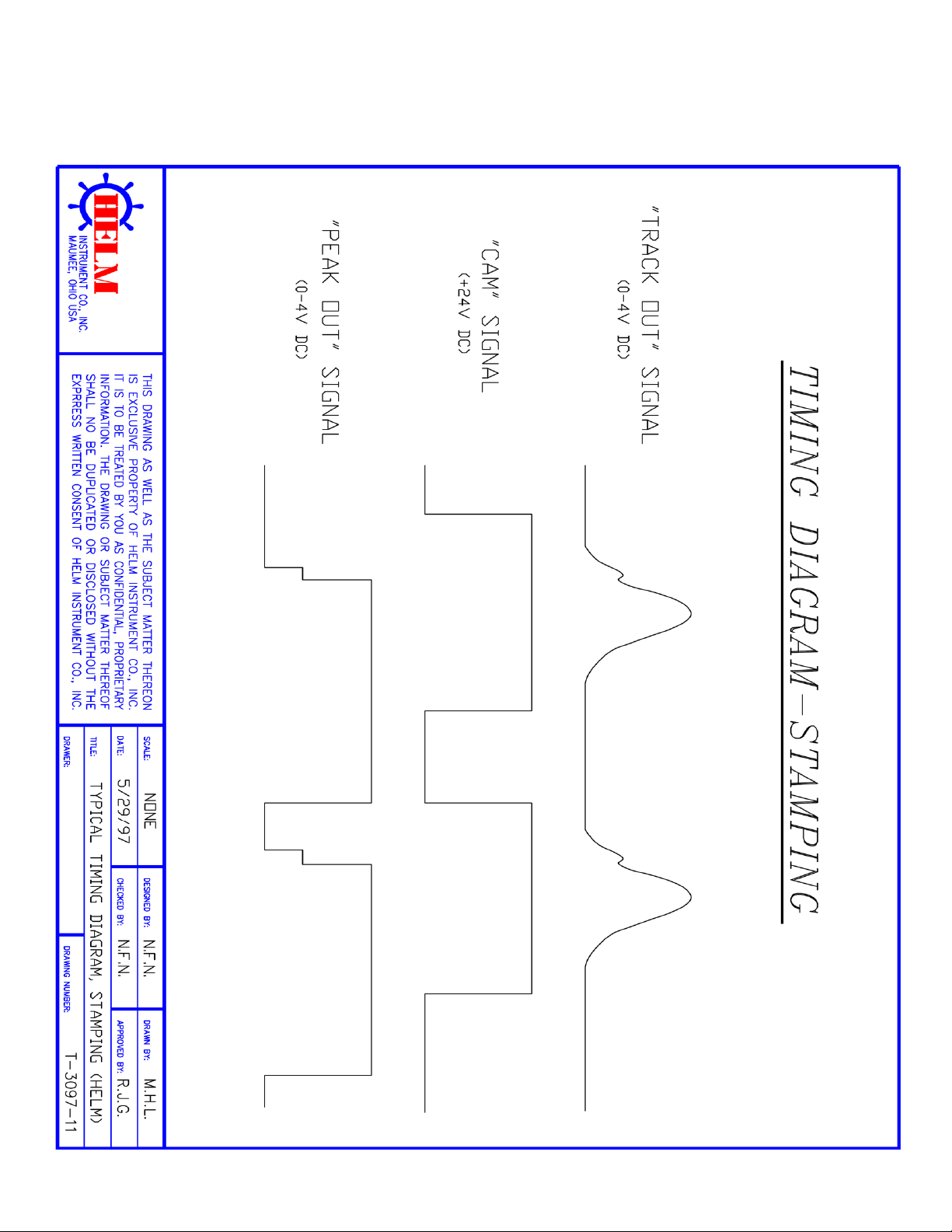
External “Peak Look Window” Timing
As stated above, an external timing signal input (“Peak Look Window”) is required for each
machine cycle to be monitored. This 24 VDC signal can be generated by a dry contact, prox
probe, or PLC output. In general, the timing signal should start shortly before the forming
load begins for the new cycle, and should end shortly after the forming load is finished. In
effect, the timing signal “tells” the module when to “look” at the forming signal for each cycle,
and to capture the “Peak” load value within that time frame. This occurs when the timing
signal is “On”. When the timing signal is “Off”, and provided that the toggle switch is set to
the lower “A/Z” (Auto-Zero) position, the “Auto-Zero Balance” function is turned o n to maintain
a proper zero balance reference. “Auto-Zero” is turned off when the timing signal is on, and
load is occurring. At the start of each new timing signal, a “Peak Reset” function happens to
reset the previous peak value, and to start the “Peak Capture” for the new machine cycle.
Normal Operation
After the set-up and calibration have been completed, the 3-position calibration toggle switch
should be set to the lower “A/Z” (Auto-Zero) position for normal operation. This allows the
“Auto-Zero Balance” function to operate between active load cycles, maintaining a proper
zero reference for accurate signal output values.
As the machine is cycled and load is placed on the sensor or load cell, the module will
generate scaled “Track Output” and “Peak Output” analog DC voltage signals. The “Track
Output” is simply the instantaneous signal output from the sensor, and is always on. The
“Peak Output” is controlled by the external timing signal with a “Peak Capture” function, and
is the overall peak signal output from the sensor for a current cycle. It is held in memory at
the end of each timing signal (“Peak Look Window”), and reset to zero by a “Peak Reset”
function at the start of the next timing signal for the new cycle.
In terms of signal output scaling, the PTM-1100 standard is 3 VDC = 100% full scale
capacity. Load values between no load and 100% capacity will yield a proportional output
signal between the particular minimum and maximum output points.
8
Page 11
PTM-1100 Operators Manual
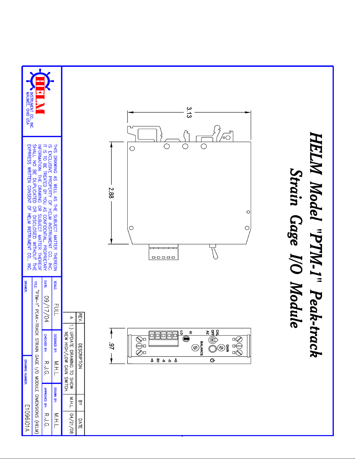
PTM MODULE DRAWING:
9
Page 12

PTM-1100 Operators Manual
PTM MODULE WIRING:
10
Page 13
PTM-1100 Operators Manual
PTM MODULE SIGNAL DIAGRAM:
11
Page 14
PTM-1100 Operators Manual
PTM-1100 USER CONNECTIONS:
12
 Loading...