

Helm P32, P42 User Manual

PAGE
1
P32/42 C
HASSIS
P32/42 Rev. 12/98
BODY BUILDERS INSTRUCTIONS
The Incomplete Vehicle Document (IVD) is supplied with each incomplete vehicle, and
provides information that should be used by intermediate and final stage manufacturers
in determining conformity to applicable Federal Motor Vehicle Safety Standards
(FMVSS). The IVD also includes information which must be followed in order to ensure
that Environmental Protection Agency (EP A) and California emissions certification re quirements and NHTSA Fuel Regulations are met.
The Body Builders Book contains information that may be used in addition to the IVD for
any manufacturer making alterations to an complete/incomplete vehicle. No alteration
should be made to the incomplete vehicle which either directly or indirectly results in any
component, assembly or system being in nonconformance with any applicable Federal
Motor Vehicle Safety Standard or Emission Regulation. Intermediate and final stage
manufacturers should be familiar with all Federal Motor V ehicle Safety Standards and
Emission Regulations and aware of their specific responsibilities as manufacturers.
For further assistance contact SVIE at: 1 (800) 875-4742
All notes are applicable to all models except where specifically stated otherwise.
Section 0 – General Instructions
Check for proper clearance between body members and chassis components which
may in any way affect the reliability and performance of the vehicle by developing abrasion and wear points from moving parts or degradation from extreme environment or
thermal exposure or may increase interior noise. Any attachments must consider chassis components for jounce and rebound motion at Maximum GVW.
Check headlamp aim and all vehicle illumination systems for proper operation when the
vehicle has been completed. Re-aim headlamps when necessary. Check for proper operation of windshield washer, wipers and defroster system.
Extreme care must be taken when working on vehicles equipped with Engine Control
Module (ECM), Powertrain Control Module (PCM), Transmission Control Module
(TCM), Vehicle Control Module (VCM), Anti-lock Braking System Model (ABS) or any
electronic unit associated with an inflatable restraint system. (See Owner’s Manual).
If arc-welding is employed on the chassis, precautions must be taken to protect all vehicle components, especially brake, fuel lines, front suspension air cylinders and fuel
tank assembly, electrical wiring and ECM/PCM/TCM, VCM or ABS. T o avoid electronic
component damage, disconnect battery (batteries); disconnect the negative cable first,
followed by the positive. T o reconnect cables; connect the positive first, then the negative.
All labels on the vehicle (any message applied to the vehicle or vehicle component that
informs, instructs, or warns) must appear on the completed vehicle so the user can read
them easily and without obstruction.
Service and service replacement parts for your add-on systems may not be available
from a GM dealer. Those installing aftermarket systems should provide information as
to where and how to obtain service.
Section 1 – Body
Accessory items such as refrigerator , hot water heater , furnace, etc., which operate on
liquid propane gas should be located and protected to prevent exposure to any flame.
Body structures, interior and accessory arrangements must be designed into the vehicle
to provide for proper load capacity and distribution on both axles and not to exceed any
gross axle weight ratings. Lateral load equalization must also be maintained. The resultant Center of Gravity of the unladen vehicle must be within the limits tabulated in the
FMVSS 105 section of the Incomplete Vehicle Document.
Body insulation provided by General Motors should not be removed. This includes any
thermal or underbody heat shields. This insulation is provided to protect the vehicle body
and occupants from excessive heat and/or provide noise attenuation. Any replacement
material internal to the occupant compartment must be certified for MVSS standard on
flammability. Areas of specific concern, but not limited to are:
D Underbody exhaust, muffler and tailpipe shields and insulators.
D Rear load floor interior insulation.
D Front floor interior insulation.
D Dash mat insulation.
D Engine cowl insulation–interior and exterior.
D Engine cover insulation.
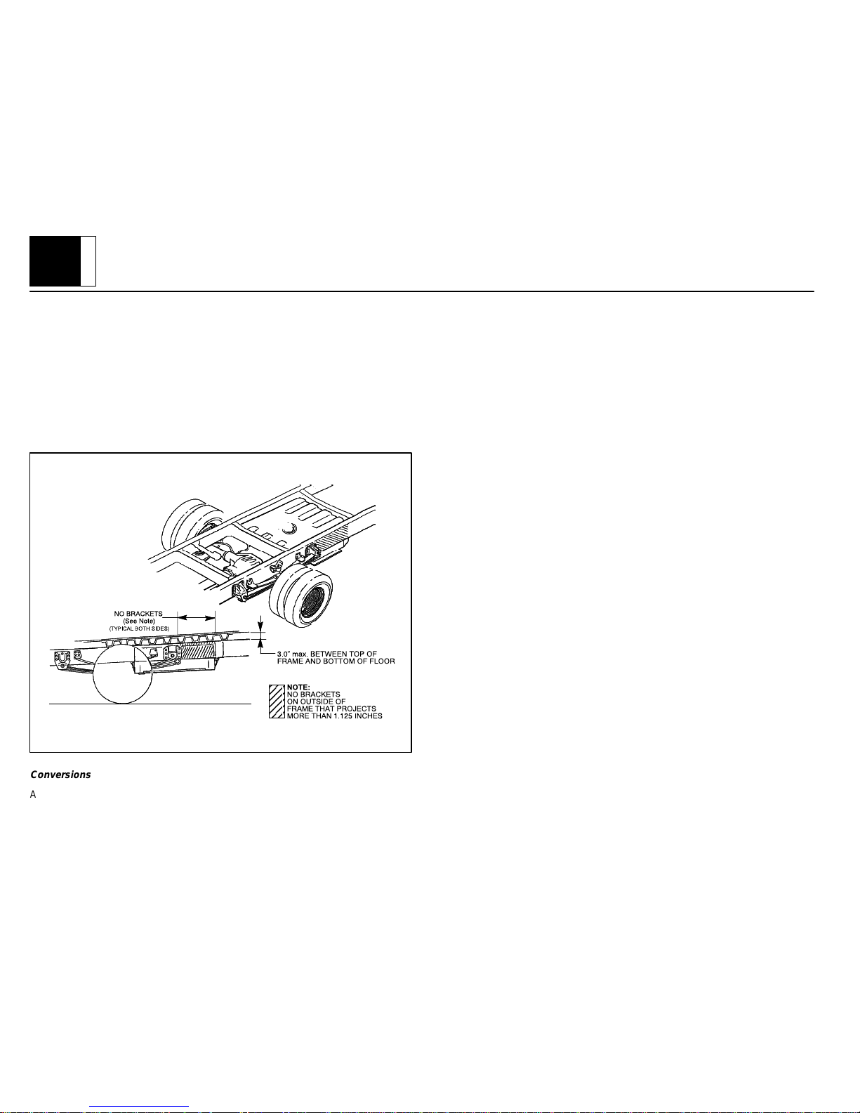
The following statement applies to P 30042 (school bus) model only
The fuel system for the school bus chassis is certified to FMVSS 301 Barrier Perfor-
mance requirements based on a body floor height not exceed 3” above the top of frame.
The 3” maximum dimension is to be measured from the bottom surface of the interior
body floor to the top of the frame. The height of any cross supports and spacers between
the bottom of the floor surface and the top of frame are not to exceed this 3” dimension.
PAGE
2
P32/42 C
HASSIS
P32/42 Rev. 12/98
No body support brackets that project more than 1.125” outside of the frame are to be
attached to the frame rail adjacent to the area of the fuel tank.
1. Any body installed by a subsequent manufacturer is mounted securely to absorb loads and prevent movement relative to the frame which could cause any
fuel system component to be punctured, separated or otherwise damaged
when tested to the applicable procedures of FMVSS 301.
2. No installed components or vehicle modifications by a subsequent manufacturer impinge on or cause distortion to the fuel system with sufficient energy to
puncture, separate. or otherwise damage the fuel system when tested to the
applicable procedures of FMVSS 301. Care should be taken that the structural integrity of the vehicle is restored following any structural modifications.
Conversions
Added bodies must be securely fastened to the basic vehicle structure. Do not attach
through side rails, but bolt securely through rail flange at floor and added reinforcing
plates. A minimum of 10_ departure angle should be maintained if frame and/or body
is extended.
Chassis
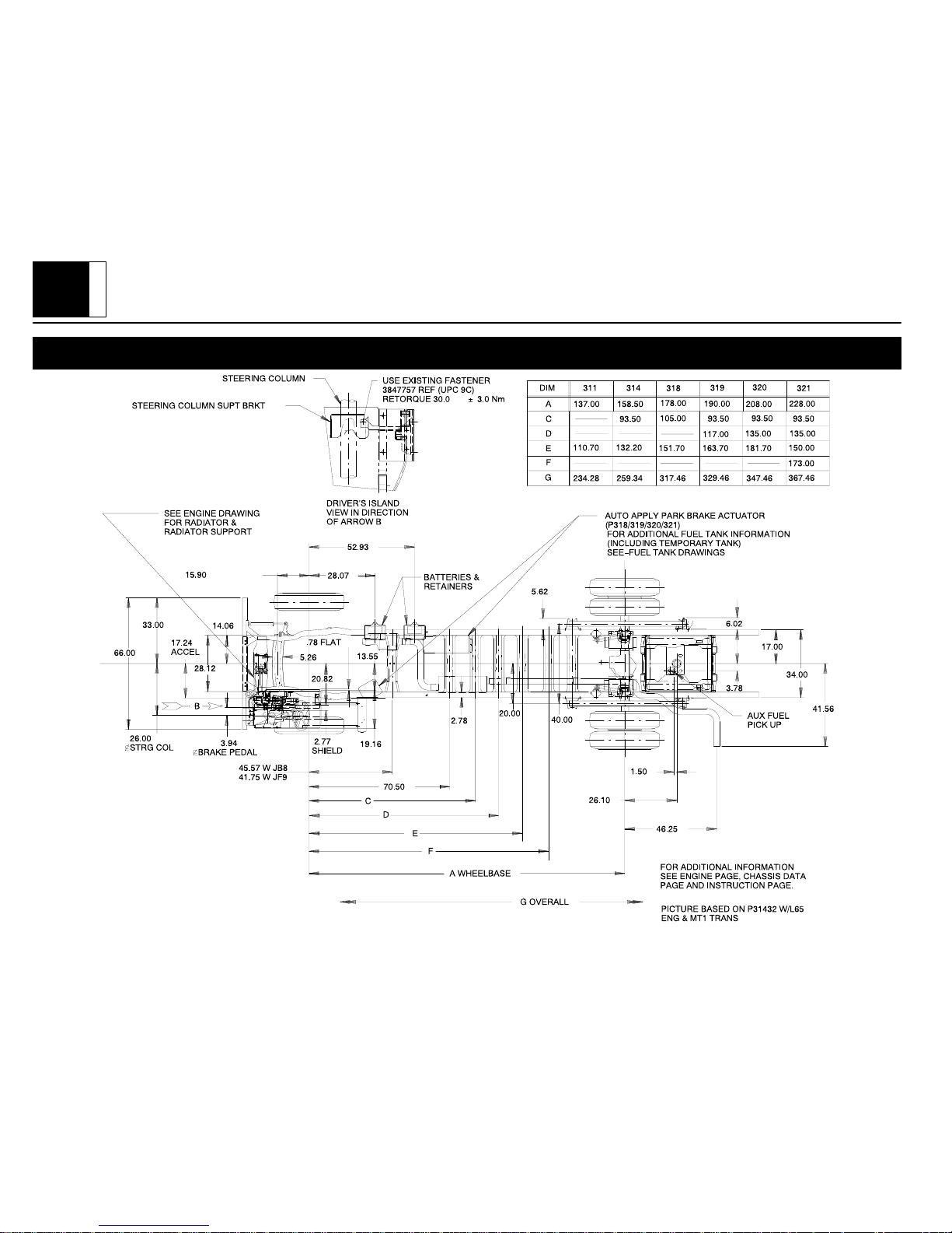
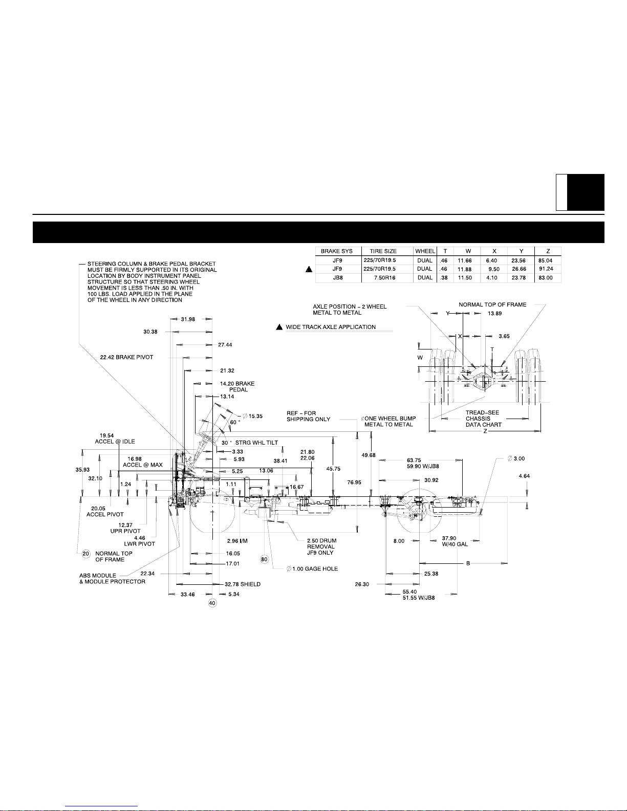
As shown on the chassis drawings, the relationship of the dash panel, brake pedal, clutch
bracket and steering column must be maintained to ensure proper operation of brakes
and steering.
Body structure must be provided to firmly support the steering column and brake pedal
brace in the fore and aft direction and laterally so that the angular dimensional geometry
shown on the chassis drawing is preserved. On all “P” truck single axle models, provi sions are incorporated in the dash toe, and frame assembly for body assembly attachments. It is imperative that the body assembly structure be integrated to the chassis
through the above parts to ensure vehicle structural integrity. If this design criteria is not
adhered to by the body builders, General Motors Corporation cannot be responsible or
liable for chassis warranty resulting from inadequate attachment of the body or the chassis.
Body underside must include inner fenders so that engine compartment is adequately
shielded from wheel splash.
The following statement applies to P 30032 model only.
The front crossmember extension must not be used as a bumper . Body Builder’s bum-
per should be attached to the front crossmember directly opposite the side rails and to
the front crossmember outboard of the side rails as required. ABS module protector extension must be maintained or replaced by equivalent part.
The following statement applies to P 30042 model only.
If the standard front bumper is not used, the Body Builder’s bumper should be attached
to the side rails and outboard of the side rails as required. ABS module protector bar
must be maintained or replaced by equivalent part.
If the body builder installs seating other than that supplied with vehicle, it is the body
builder’s responsibility to ensure that the seating and restraint systems comply with
FMVSS requirements. The restraint systems supplied with the vehicle were designed
to accommodate the seating reference points and seat travel of the original equipment
seats only.
Air Conditioning
For additional information refer to
Engine - Section 6.
NOTE: Air conditioning systems using R-134A refrigerant are equipped with metric
fittings to prevent interchange with R-12 refrigerant components. Do not
interchange R-134A components, refrigerant oil or service equipment with
R-12 components, refrigerant oil or service equipment.

PAGE
3
P32/42 C
HASSIS
P32/42 Rev. 12/98
Section 2 – Frame
Hole drilling, welding, modifications, or alterations to the frame assembly are the responsibility of persons performing these operations. These same individuals assume complete responsibility for frame assembly reliability , performance after alterations and compliance to applicable FMVSS requirements.
The following procedures and specific precautionary instructions are recommended for
proper installation of special bodies and/or equipment on GM frames. Failure to follow
these recommendations could result in serious damage to the basic vehicle.
Flanges
Do not drill holes in frame flanges:
D Within 20 mm (0.75 in.) of radius tangent and 25 mm (1.0 in.) of raw edge.
D Larger than 12 mm (0.50 in.).
D Closer to each other than twice the hole diameter.
Holes
Holes to mount brackets, supports, and out-riggers must be drilled in the vertical side
rail web with the following restrictions:
D Material between edge of hole and inside of upper or lower flange must not be less
than 37 mm (1.50 in.) for low carbon steel (36,000 PSI yield).
D The minimum edge distance between any two (2) holes must be larger than twice
the diameter of the larger hole.
D No holes should exceed 20 mm (0.75 in.) in diameter.
D All holes should be drilled in the frame using appropriate drilling practice and
safety precautions.
Welding
CAUTION: Fuel tank and fuel lines must be drained and all vapors purged to ensure
non-combustible mixture before any welding, brazing or soldering.
When welding low carbon steel side rails, crossmembers and brackets (32,000 or
36,000 PSI yield strength), emphasis is placed upon weld application techniques to
avoid stress risers that may adversely affect frame operating stresses.
When welding is performed anywhere on the vehicle, precautionary measures should
be taken to prevent damage to electrical system wiring, front suspension air cylinders
or components. Prior to any welding, parts or components which could be damaged by
excessive temperatures must be removed or adequately shielded; the battery cables
should be disconnected at the battery . Also prior to welding, the area to be welded and
surrounding area must be cleaned of all frame protective coating. After welding, when
parts are cool, carefully inspect wiring and electrical components for shorts or other damage which could draw excessive currents and possibly cause an electrical system short
when the battery is reconnected. Apply protective coating to areas where coating was
removed.
Alterations
If the wheelbase is modified the alterer must take responsibility for compliance with affected motor vehicle safety standards and for warranty on items such as driveshafts, universal joints, center bearings and rear transmission tailshaft, transmission case frac tures, output shaft bushings, bearings, brakes, fuel systems and any other related
component failures. Wheel base modifications can affect the operation of the ABS system and may alter vehicle braking stability and or compliance with FMVSS 105. Additionally, the customer must be alerted in the modifier’s owners manual that parts for the reworked area are not available through the General Motors service parts system.
Shear Plate Attachments
Attachments of shear plates should be accomplished by using existing manufacturing
holes already available in the frame side rails. Manufacturing holes, normally 16 mm in
diameter, are consistently placed along the frame side member in the center of the web
on each frame.
When additional holes are required for shear plate attachment, they should be no larger
than 20 mm (0.75 in.) in diameter. Holes are to be drilled no closer than 63.5 mm (2.5
in.) apart. For holes drilled forward of the rear axle, centers are to be no closer than 63.5
mm (2.5 in.) from the top or bottom flanges and no closer than 89 mm (3.5 in.) from any
suspension attachments. For frame holes drilled rearward of the rear axle, hole centers
are to be no closer than 51 mm (2.0 in.) from the top or bottom flange and no closer than
89 mm (3.5 in.) from suspension attachments.
No additional holes or notching of either top or bottom frame flanges is allowed.

PAGE
4
P32/42 C
HASSIS
P32/42 Rev. 12/98
Body tie-down holes should only be drilled in top flange no larger than 0.76 in diameter;
centerline of holes should be 1.0 to 1.12 in. from the web side of the frame rail. Minimum
distance between edges of the holes should be approximately 2.0 in.
Trailer Towing
The Incomplete Vehicle Document also specifies that the CG location be within certain
limits for proper brake balance, and may be more restrictive than the data mentioned
above. The Body Builder must use all appropriate data.
NOTE: Failure to keep body and payload CG at least 26” forward of centerline of rear
axle will result in degradation of trailer towing capacity. Consult with your Body
Builder/Final Stage Manufacturer to determine maximum tongue load for your
vehicle.
Section 3 – Front Suspension
See chassis data information for clearances and assistance in calculating trim heights.
Clearance should be provided for the tire used while in full jounce (upward travel) against
metal stops and at full left-hand and right-hand turn. The envelopes will be provided
upon request. See
Section 5 - Brakes
.
Allowance for the tire chain clearance shown on a maximum grown tire must allow for
(1.66 in.) clearance to the sides of the tire and (2.5 in.) to the top of the tire. Be sure suffi cient clearance is provided for suspension, axle and tire and wheel in full vertical travel
(up and down).
NOTE: Notification to the consumer may be required in certain states if tire chains
cannot be used.
Vehicles equipped with 3650 lbs. low height independent front suspension (IFS). The
urethane air cylinders must be maintained at 70 psi. If the vehicle is also equipped with
option 9Q6, right side air cylinder should be set at 50 psi instead of 70 psi. Vehicles
equipped with 4500 and 5000 lbs. independent front suspension (IFS) urethane air cylinders must be maintained at 50 PSI; with 5500 lbs. independent front suspension, air cyl inders must be maintained at 90 psi. Air cylinders when provided must be shielded dur ing welding operations.
Since there is a large variation in completed vehicle front weight due to differences in
body weight and equipment, the front suspension alignment (caster, camber and toe)
must be checked and reset if necessary after the vehicle is completed. The suspension
must be reset by the Body Builder if it is found that the setting’ s do not conform to the
specifications as outlined in the “P” Chassis Service Manual. On P 30042 trucks with
I-beams, camber and caster is designed into the axle/suspension and cannot be adjusted.
See Truck Service Manual for complete alignment procedure, specifications under
“Diagnosis and Front Alignment” section.
The following statement applies to P 30042 models with I-beam front axle.
The front crossmember steering gear attachment is a weldment. Under no conditions
may the flanges be cut or notched out in any manner . Any alteration would severely affect steering attachment capabilities.
Section 4 – Rear Suspension
Clearance to body should be provided for the suspension, axle, driveshaft and tires under the following conditions: (1) Axle in full jounce against the metal-to-metal stop, (2)
Axle at 4.5_ roll with one side of axle in full jounce at the metal to metal stop and (3) Axle
at design position. Allowance for the tire chain clearance shown on a maximum grown
tire must allow for (1.66 in.) clearance to the sides of the tire and (2.5 in.) to the top of
the tire. Be sure sufficient clearance is provided for suspension, axle and tire and wheel
in full vertical travel (up and down).
NOTE: Notification to the consumer may be required in certain states if tire chains
cannot be used.
Pipes, wiring, conduits and any other related components must not be placed where they
cross the path of motion of the rear axle, driveshaft, axle brake pipes, hoses, spring or
tires. Such crossing could result in rupture, wear-through, or separation due to normal
axle motion.
See chassis data information for additional clearances and for assistance in calculating
trim heights.
Section 5 – Brakes
See Truck Service Manual for brake specifications.
Due to the critical nature of brake systems, anyone making modifications or alterations
must assume complete responsibility for system reliability , performance and certification
to FMVSS 105 or FMVSS 121.

PAGE
5
P32/42 C
HASSIS
P32/42 Rev. 12/98
It is mandatory that no change be made to the brake main cylinder location, brake pedal
push rod length or pedal position.
Ensure that hydraulic brake system is free of air and hydraulic leaks. Bleed brakes if
required, following procedures as outlined in truck chassis service manual. Ensure that
vacuum booster system or hydroboost system is functional and free of leaks.
Check master cylinder fluid level and fill as necessary. (Refer to Owner’s Manual)
Check power steering fluid level for models equipped with hydroboost brake. (Refer to
Owner’s Manual)
Added floor covering or carpeting must not restrict service or parking brake pedal travel
from released position to full pedal travel.
The body builder must provide access to brake master cylinder to enable fluid level
check and the ability to add fluid as required. Clearance to master cylinder should be
provided to enable its easy removal and replacement if ever required. Visual access to
warnings printed on master cylinder reservoir must be provided per FMVSS 105.
The body builder must also provide access to auto-apply parking brake actuator switch
on all 16,500 lb. GVW chassis. Opening for service in brake shield on chassis below
drivers island must remain clear.
No body part or chassis-mounted component including wheel house shields may be located within 2.0 in. of brake hose routing and/or wheel speed sensor wire in all wheel
and axle positions. All exhaust system components must also have a minimum of 2.0
in. clearance to brake hoses in closest positions. (Be sure to account for brake hose and
sensor wire travel with suspension).
Body builder is to verify that the brake light switch and brake warning switch is operative.
This includes both the brake system differential pressure and parking brake actuator
switch. Any ABS system codes that may have been set due to the body build process
must be checked and cleared prior to customer delivery.
The following statement applies to models with B3D school bus option only.
Hydroboost systems are equipped with a brake fluid flow indicator . Alarm system must
be completed by the body builder. Shipped in a loose parts box are a buzzer module,
time delay module and wire harness, which must be installed per instructions shipped
with the loose parts box.
Floorboard and toe pan position cannot be altered, as it will interfere with brake and accelerator pedal movement or cause driver discomfort. The floor may be covered with
normal pad and carpeting only (except P30032/42 models). No floor covering should
be under the accelerator pedal area it will interfere with accelerator control movement.
Carpeting must have 1” minimum clearance to the accelerator pedal and should be cutpile only. Carpeting must be properly secured to prevent any movement.
Parking brake installation and adjustment procedure:
1. Secure vehicle in place with hoist or wheel chocks and place vehicle transmission in park position.
2. Front cable routing throughout body must have a minimum radius of 6 in. and
be protected from all moving components and sharp edges.
3. For transmission mounted parking brake:
The following applies to all P 30042 models with the exception of P 31842 & MT9
Hand lever
1. Release parking brake handle and remove cotter pin, washer and clevis pin
inserted from outboard side of vehicle. Mount handle convenient to driver
comfort range.
2. Feed cable through body and reattach to handle with clevis pin inserted from
outboard side of vehicle.
3. Readjust parking lever knob to give a definite snap-over feel (approx. 60 lbs.)
when the lever is applied. With the lever in the applied position, the forward
edge of the clevis pin head should be approximately 5/8 in. from the end of the
adjusting slot on the bracket.
4. Do not alter the drum or cable adjustment at transmission unless routine service is required in order to obtain the desired setting above. No drag should
be present after parking brake handle is released.
The following applies to all P 30032 models and P 30042 & MT9
Foot pedal
1. Release foot pedal and remove cotter pin, washer and clevis pin inserted from
outboard side of vehicle. Mount pedal coinvent to driver comfort range.
2. Feed cable through body and reattach to handle with clevis pin inserted from
outboard side of vehicle.
3. Readjust parking brake pedal to give a firm pedal at 2-5 clicks (P 30032) and
at 8-16 clicks(P 30042 & MT9) when the pedal is applied. With the pedal in
the applied position the forward edge of the clevis pin head should be approximately 5/8 in. from the end of the adjusting slot on the bracket.
4. Do not alter the drum or cable adjustment at transmission unless routine service is required in order to obtain the desired setting above. No drag should
be present after Parking brake is released.

PAGE
6
P32/42 C
HASSIS
P32/42 Rev. 12/98
For rear axle mounted parking brakes (P 30800, P 31100, P 31432 with out JF9):
1. Release parking brake handle and remove connector between front and intermediate parking brake cables. Remove front cable from frame bracket and
floor pan assembly.
2. Feed cable and handle assembly through body and re-attach handle to body
convenient to driver’s comfort range.
3. Feed cable back into frame bracket and making sure tangs lock into position.
Place connector back on front and intermediate brake cables.
4. With lever in the applied position, turn adjusting knob to give 5/8 in. clearance
from forward edge of clevis pin head to end of adjusting slot in bracket.
5. Do not alter rear brake drum adjustment or cable equalizer unless routine service is required in order to obtain the desired settings above.
Auxiliary Braking Systems
If add-on braking systems are installed to control either tag axle or trailer braking sys tems, the body builder is responsible for the integrity of the system. This may require
running FMVSS certification tests. Any change to the GVWR necessitate, recertification
to FMVSS. Care must be taken to assure that flow rate of the brake fluid is not affected
by the modification, as this could reduce the effectiveness of the ABS system. The recommendations of the auxiliary brake device manufacture should be followed in making
the modifications. For most systems that require a tap-in is best done near the rear axle
of the vehicle. This allows any proportioning of the rear brakes to be communicated to
the auxiliary brakes. This tap-in should not require more than .02 cu. in. of fluid, and be
capable of withstanding pressures up to 3000 psi. Auxiliary brakes must be capable of
taking the proportion of the braking load, for which, they are designed to provide for the
overall vehicle (combination) irrespective of fade or other operating effects.
Section 6 – Engine
For additional information refer to
Sectio n 1 – Bo d y.
Air conditioning and auxiliary belt-driven equipment installation recommendations:
No alterations or additions to the accessory drive belt system will be warranted on ser-
pentine belt systems.
The serpentine belt type of drive is designed as a total system, incorporating a single poly
V-belt and an automatic tensioner . In this type of system, degrees of pulley wrap, belt
tension, and pulley alignment are very critical factors. Modification is not recommended.
Due to the critical nature of the accelerator system, anyone making modifications or alterations assumes complete responsibility for system reliability , performance and com pliance to FMVSS 124. Caution must be exercised so that the accelerator cable is prop erly routed. Specifications are as follows:
D Route cable to maximize all bend radii. In no case should bend radii be less than
3 in. (76 mm).
D Minimum distance from exhaust manifold to be 6.0 in. (150 mm), unless a heat
shield is provided.
D Do not use accelerator cable or clips to route wires, harnesses or other cables.
Cable sheath must be clipped so as not to pinch inner cable. Cable must not be
loose in clip allowing sheath to move when accelerator pedal is applied and
released.
D Cable must not be subjected to kinking or routing across any sharp edges.
D Cable routing must be perpendicular to the surface of the front-of-dash at the
dash fitting. No objects or routings should force cable to have a bend at the dash
fitting. Flexible components (hoses, wires, conduits, etc. ) must not be routed
within 2.0 in. (50 mm) of moving parts or accelerator linkage unless routing is
positively controlled.
D Caution must be taken so that the accelerator pedal remains properly located.
Guidelines for accelerator pedal locations are as follows:
— Ensure that the accelerator can freely operate from idle to wide-open throttle
position and return. Make sure that the pedal will not hang up on any nearby
items such as carpets, floor, screws, wiring harnesses, etc. Engine cover
should have at least one inch (25 mm) clearance to side of accelerator pedal
with the carpet mat installed. No floor covering should be installed under pedal
area.
— Accelerator to brake pedal relationship has been designed to provide mini-
mum driver movement and should not be altered in any way.
Gasoline engine induction and/or ignition system is certified in compliance with the Federal Vehicle Emission Standards. Any alterations to the systems or components could
void compliance and render the vehicle illegal. System includes:
D Fuel system – Sequential port fuel Injection (SPFI), central port injector (CPI) and
associated tubes, hoses and pipes, air cleaner outside air hose, fuel pump and
inlet manifold and fuel vapor canister.
D Exhaust system.
D Ignition system distributor and initial spark timing setting, spark plugs, spark plug
wires.

PAGE
7
P32/42 C
HASSIS
P32/42 Rev. 12/98
D Crankcase ventilation system.
Diesel engine induction and injector pump system is certified to be in compliance with
the Federal Vehicle Emission Standards and/or Noise Standards. Any alterations to the
system or components could void compliance and render the vehicle illegal. System includes:
D Fuel system – Injection pump, injector lines and injectors, fuel return hoses and
pipes, air cleaner, outside air hose, fuel pump, fuel filter, fuel heater assembly and
intake manifold.
D Exhaust system.
D Crankcase pressure regulation system.
D External engine components such as air cleaner , crankcase pressure regulator
valve, alternator, injection pipes, fuel return hoses from injectors, exhaust
manifolds, oil fill pipe, etc. must be provided with sufficient clearance for engine
roll and torque.
D When a vehicle is equipped with a electronic fuel injection (EFI) engine, it has an
engine control module ECM/PCM/TCM or VCM. This ECM/PCM/TCM or VCM
must be maintained at a temperature below 185_F at all times. This is most
essential if the vehicle is put through a paint baking process. The ECM/PCM/TCM
or VCM will become inoperative if its temperature exceeds 185_F. Therefore, it
is recommended that temporary insulation be placed around the ECM/PCM/TCM
or VCM during the time the vehicle is in a paint oven or undergoing another high
temperature process.
Engine starting instruction label location. Label should be installed 2 in. above driver’s
sunvisor bracket and 2 1/2 in. to the left of the right hand bracket.
The following statement applies to models with remote mounted air cleaners:
The Body Builder must install the air inlet duct such that it provides cool dry air to the air
cleaner. Radiator baf fling must be provided to prevent recirculation of air through the
radiator. The air inlet must be shielded from water and snow that may come from the
road, tires and through the grille.
The air cleaner position and ducting between the air cleaner and engine should not be
modified.
The following applies to P models with L29/L31/L35 engines:
The relationship of the air cleaner assembly to the Mass Air Flow sensor (MAF) as posi-
tioned by the air cleaner elbow cannot be altered. The MAF sensor black electronic module must remain 30_ forward of vertical.
The following statement applies to P 30032 models with a 6.5L turbo diesel engine.
CAUTION: Do not run the engine with the air cleaner or ducting to the turbo removed.
Serious personal injury or damage to the engine could result.
Apply a Caution label on the turbo inlet ducting.
Apply Starting Fluid Warning label in a visible area near air intake duct inlet.
Refer to information in the Loose Parts Box for labeling and air inlet duct part numbers.
Section 7 – Transmission
Light duty models equipped with manual transmission have a clutch-operated start safety switch. Starter should operate whenever the ignition is turned to start and the clutch
is fully depressed. The clutch-operated start safety switch is integral with the clutch master cylinder push rod. It is
not
adjustable.
Models equipped with automatic transmissions and column shift control have a steering
column mounted neutral/park start safety mechanical lockout feature, which interfaces
with the steering column ignition switch. Starter will only operate when gear shift lever
is in the neutral or park position. Re-adjust the shift linkage if necessary as outlined in
the Truck Service Manual.
Transmission shift cable must be routed and clipped properly to avoid contact with hot
surfaces such as exhaust manifold or EGR pipe.
NOTE: Remove the shift cable clearance tag from the EGR tube after shift cable
routing.
Models equipped with brake-transmission shift interlock (BTSI) must fully apply the regular brakes before you can shift from park when the ignition key is in the run position.
Models equipped with manual transmission use a hydraulic clutch actuator. Check fluid
level as outlined in the vehicle owners manual. Attach manual transmission shift lever
boot to floor using four 11514843 screws or equivalent.
It is mandatory that no change be made to the clutch master cylinder location, clutch
master cylinder push rod length, or pedal position.
After installation of the body, vehicles with automatic transmissions should have the shift
linkage checked and adjusted if necessary as outlined in the Truck Service Manual.

PAGE
8
P32/42 C
HASSIS
P32/42 Rev. 12/98
Shift Cables
D Control cables should be supported or anchored to prevent sag when suspended
overhead and to prevent movement where the routing bends.
D On long control runs the conduit should be clamped to supporting structure at
least every 48 inches.
D Supports should be placed at the end of the straight runs, and not in the middle
of a bend.
D Care must be taken that the clamps do not collapse the conduit and increase
control friction.
D Controls should be routed so that they will avoid rubbing, pinching and extreme
heat, cold or vibration.
D Bend radius to be 6.0 in. minimum.
Section 8 – Fuel and Exhaust
Fuel Systems
Any body installed must be mounted securely to absorb loads and prevent movement
relative to the frame which could cause any fuel system component to be punctured, separated or otherwise damaged when tested to the applicable procedures of FMVSS 301.
No other installed components or modifications are allowed which could impinge on or
cause distortion to the fuel system with sufficient energy to puncture, separate or otherwise damage the fuel system when tested to the applicable procedures of FMVSS 301.
Due to the critical nature of the fuel system, anyone making modifications or alterations
to the existing system, except as specified in the Incomplete Vehicle Document or in this
manual, must assume complete responsibility for the systems reliability, performance
and compliance to FMVSS 301.
Assembly of any fuel system components may require application of a lubricant to prevent contamination of the fuel system, only GM lubricant 9985784 may be used.
The fuel evaporative emission control equipment is certified to be in compliance with the
Federal and California V ehicle Emission Standards. Metal fuel lines and fuel tanks have
a surface coating to reduce corrosion on inside and outside surfaces to comply with useful life requirements. All fuel hoses are made of a low permeation multilayer material to
comply with enhanced evaporative emission requirements. Any alterations to systems
or components including materials, hose lengths and their location, except as described
in the fuel fill system modifications section, could void compliance.
The system includes:
D Fuel tank, fuel level sender , fuel fill and vent hoses and pipes, emission canisters,
fuel feed, fuel return and vapor lines, purge control solenoids, fuel fill cap and
canister vent solenoid.
For these reasons,
NO ALTERATION OF THE FUEL SYSTEM IS RECOMMENDED
Temporary Tank
The temporary fuel container must be replaced with a permanent fuel tank prior to placing the vehicle into use. The replacement tank supplier and/or body builder is responsi ble for certifying evaporative emissions.
The following statement applies to motorhome chassis only.
The unit is fueled during shipping (gas engines only) from a temporary fuel tank which
contains the tank unit for the main tank. The temporary tank is to be removed and
scrapped. Transfer the tank unit with O–ring seal to the main tank. The fuel cap for the
main tank filler neck is the same as on the temporary tank. Remove the tank unit hole
cover and lock ring. Discard
only
the tank unit hole cover and the lock ring. Reinstall
the seal, lock ring and the tank unit assembly.
The 75 gallon fuel tank (RPO NJ9) as received has a vented plug marked “For Shipping
Purposes Only”. This plug is to be removed and a solid steel plug shipped in the ship
loose box must be installed in place of the plug removed.
The 75 gallon fuel tank (RPO NJ9) is provided with rear shields to provide protection for
the departure angle shown on the fuel tank arrangement drawing. Any alteration or deletion of these shields requires that an equivalent departure angle of protection be provided by the completed vehicle.
The following statement applies to commercial models with option B3D only.
The CPI fuel system for standard models is connected to the regular fuel tank. The fuel
system for option B3D gasoline and diesel school bus models is also equipped this way .
A fusible plug is included in the loose parts box. This must be installed into the tagged
hole in the tank to replace a plastic shipping plug.
Fuel Fill
Fuel tank filler pipe location should be so situated and constructed as to prevent gasoline
vapor from emitting to vents of pilot flamed devices and to body and engine compartment
air inlets.

PAGE
9
P32/42 C
HASSIS
P32/42 Rev. 12/98
It is recommended that when mounting the fuel filler pipe assembly and vent hose that
a minimum of 3” clearance be provided to any body component to prevent contact between hoses and/or mating parts and that retention be provided to ensure routing and
prevent failure due to wear and fatigue. Filler pipe and vent line must have a gravity fuel
flow to tank at all times; no fuel traps are allowed. Alterations of fuel line routings could
affect the ability of the completed vehicle and are, therefore, not desirable. The complete
fuel system must comply with FMVSS 301.
If additional new hose is required when installing fuel tank filler neck, this hose must be
suitable for use with unleaded fuels or diesel fuel respectively and must allow the vehicle
to meet enhanced evaporative emissions requirements.
The fuel fill inlet pipe assembly attached to the body must be grounded to the frame struc ture with the ground strap and fasteners provided in the shipped loose box.
Fuel Lines
Fuel line routing precautions:
D 12 in. minimum clearance to exhaust system is required or a metal shield must
be provided.
D Fuel lines should be clipped to chassis to prevent chafing. Metal clips must have
rubber or plastic liners.
D Use corrosion resistant steel tubing with short sections of approved hose to
connect components. Hose-to-tube connections should be clamped for diesel
systems. Steel tube ends should be beaded for hose retention. Fuel supply is
pressurized by an in-tank pump for CPI systems. Coupled hose or nylon
quick-connects must be used. Clamped hose is not acceptable for CPI systems.
All engines require a fuel return system which returns excess fuel from the injection
pump and injector nozzles back to fuel tanks. Care should be taken that these lines are
not blocked nor their hoses pinched. The engine may run poorly or stall if these lines
are restricted or blocked.
All gasoline engine vehicles are equipped with fuel evaporative emission control equipment which is certified to be in compliance with the Federal or applicable California vehicle emission standards. Alterations to fuel tank and metering unit, lines, canister or
canisters, canister filters, canister purge control valves, relay switches, tank auxiliary
vent valve, engine speed controller , or other devices/systems are therefore not allowable
since vehicle adherence to C.A.R.B. and Federal regulations may be affected.
Diesel powered vehicles incorporate water drain provisions in the fuel system. These
valves are only to be opened when siphoning water and contaminants from the fuel sys tem.
Fuel Tank
For vehicles with full frames, the tank must have a minimum clearance of 2 in. top, front,
rear and sides to body and other supports.
T ank may be pressurized with nitrogen (Do not use air with fuel in the system) to 1.25
PSI maximum to check for final line leakage or for forcing fuel through the system. Pressures greater than this amount may be detrimental and affect tank durability.
The following statement applies to commercial models only.
T apping into the main fuel supply line to get fuel for a powered motor generator is not
recommended since this could result in fuel starvation, vapor lock problems and running
the fuel tank dry . It is not permissible to draw fuel from a fuel return line. The fuel meter
assembly has a anti-siphon feature in the return line that prevents fuel from being drawn
out.
The following statement applies to motorhome models only.
The 40, 60 & 75 gallon gasoline tanks will include a fuel draw tube in the top of the tank
assembly. This is provided for body builders to use for generators. The body builder
should remove the pipe plug in this fitting and plumb system to the generator from this
pickup point. Added auxiliary power unit must use the same fuel as the chassis engine
or a separate fuel system will be required.
The use of auxiliary fuel tanks is not recommended.
If an auxiliary fuel tank is added,
the alterer must take responsibility for compliance with affected motor vehicle safety
standards. Also, if an auxiliary fuel tank is added to a gasoline-powered vehicle, the fuel
must be drawn through a pipe at the top of the tank (balance line between tanks is not
permitted).
Gasoline fueled vehicles are now equipped with a fuel pump return line. If an auxiliary
tank is added, the tank selector valve must include a return port which returns fuel to the
tank from which the fuel is being drawn.
In gasoline engines the fuel pump is located in the fuel tank. The battery must be disconnected before starting any work on the fuel system.
In the use of dual fuel systems, the vehicle operator should strictly adhere to the
manufacturer’s procedures for switching from gasoline to gaseous fuel operation. Improper switching procedures may result in overheating and damage to the exhaust system and the vehicle. The gaseous fuel tank should not be mounted in an enclosed area
of the vehicle, such as the passenger compartment, truck, etc., and the system should
be vented to the outside of the vehicle. In addition, vehicles converted to gaseous fuels
should not be stored in enclosed places such as garages. Further, General Motors cau-

PAGE
10
P32/42 C
HASSIS
P32/42 Rev. 12/98
tions purchasers that the design, location and installation of any type of fuel storage system involves significant technical and engineering considerations and that these statements on gaseous fuel conversions should not be interpreted to be an approval by
General Motors of any modification to the original equipment fuel system.
Conversions to gaseous fuel should be made in conformance with applicable Federal
and State regulations. Removal of emission-control components, or the addition of gaseous fuel systems which could damage or reduce the longevity of those components and
could also cause the mechanical and emission performance warranty to be voided.
Exhaust System
Particular care should be taken to prevent the possibility of exhaust fumes and carbon
monoxide exposure to vehicle occupants in units completed by body builders. Holes and
openings through the floor and all other parts of the body must be permanently and adequately sealed by the body builder to avoid exhaust intrusion into any occupant area.
If it is necessary to change the exhaust outlet location, the exhaust discharge must be
unobstructed and directed away from occupant areas. Alteration of the exhaust outlet
or its position may increase exhaust noise and render the vehicle illegal in those areas
with pass-by noise regulations. All vehicles >10,000 lbs. GVWR come under Federal
noise regulations, vehicles <
10,000 lbs. GVWR are regulated by various state and local
regulations of the Environmental Protection Agency; see those regulations for rules, test
procedure and noise levels permitted.
T ail pipe outlet location must be tested statically and with the vehicle in motion to ensure
that exhaust gases do not penetrate side or rear windows or under body seams and
holes. Auxiliary power plants should also be tested under the same conditions. T ail pipe
extension must extend 2.0 to 2.5 in. outboard of body side panels. T ail pipe exit ahead
of rear wheels is not recommended.
Check for leaks in exhaust systems and repair as required.
Exhaust temperatures can exceed 1600_F under extreme operating conditions, with
pipe surface temperatures slightly less than this. Extreme care must be used when placing body components in the proximity of the exhaust system so as not to exceed the rated
temperature limits of the components. Due to variants in underbody configurations of
the vehicles, we are not in a position to make recommendations on how to insulate or
design components in the proximity of the exhaust system.
Each manufacturer must make temperature checks of critical areas of his vehicle and
adjust his design accordingly , or provide shielding to ensure safe operation of his body
components.
The same can be said for the engine compartment. Obviously there will be additional
heat radiated from the engine. How much is retained in the area will depend on how well
this area is ventilated in your individual designs. Here again, temperature checks of interior areas surrounding the engine should be made to determine if your insulation is ade -
quate. This is the same engineering practice we have followed on our complete vehicles
incorporating these exhaust systems.
Exhaust system materials are selected and tested to withstand the operating environment of the vehicle. Do not modify the exhaust system in any way. The tail pipes are
made of 409 stainless steel or aluminized 409 stainless steel.
Heat shields are mounted to the underbody and/or exhaust system components (catalytic converter and muffler). Shields for the propshaft hanger bearings are also provided
in some vehicles.
Section 9 – Steering
Check power steering fluid level and system operations. (Refer to Owner’s Manual)
Steering wheel and horn pad must not be altered or replaced.
The following statement applies to motorhome chassis only.
Steering wheel and shaft must be located and supported as shown on the body builders
drawing.
Section 10 – Tires/Wheels
Check wheel lug nuts for proper torque; specifications are provided in the Owner’s
Manual.
Substitution of tires of greater capacity than those offered as original equipment by vehicle manufacturer is not approved for use on original equipment wheels. Any usage of
higher capacity tires must be accompanied by higher capacity wheels. However, the
wheel offset and distance from centerline of rim to wheel mounting face must be the
same as the replaced original equipment wheel to ensure proper wheel bearing loading
and clearance of tires to body and chassis components.
Increasing tire and wheel capacity does not necessarily increase vehicle GVW ratings.
It is recommended that tire chain clearance guideline, J683 from the Society of Automo-
tive Engineers be adhered to in designing rear wheelhouse clearance.
Check tires and inflate to recommended tire pressure according to the tire pressure infor-
mation displayed on the certification/tire label provided with the vehicle before shipment
of vehicle from Body builder.
Any substitution of tires may affect Speedometer/Odometer accuracy.

PAGE
11
P32/42 C
HASSIS
P32/42 Rev. 12/98
If the body builder installs wheel covers on the vehicle, vented covers must be used. The
minimum vent area is to be the greater of 34 in.2 or 90% of the original vehicle’s wheel
vent zone. Air flow through the wheel vent and cover vent must be direct.
Section 12 – Electrical Battery and Battery Cables
The vehicle battery should be located and positioned to make use of the existing battery
cables. If the battery requires relocation and longer cables are required, a proportionately larger gauge wire must be used. If in relocating the battery the negative ground cable
is attached to frame rail, a cable of similar gauge be provided between the frame rail and
the engine. This is required due to the heavy electrical loads imposed by the starting
circuit. T o ensure proper operation of the battery cables the following chart on length,
gauge and materials must be strictly adhered to:
Combined Length of Positive and Negative
Cable Gauge Cable in Inches (Copper)
4 66
2 107
0 170
If the battery requires relocation in the engine compartment, the OEM supplied generator with flat-compensated regulator must be replaced with a generator with temperature
compensated regulator to regulate system voltage compatible with underhood battery
temperatures.
Underhood Battery Location
OEM Part No. Substitute Part No.
10480170 (105 A) 10480168 (105 A)
10480267 (124 A) 10480255 (124 A)
If the battery is relocated in the engine compartment without replacing generator as
stated above, it will effect the battery life and will be reduced by 50% of the average battery life.
Battery Installation
The battery and cable installation, provided by the body upfitter, must comply with the
following guidelines. Non-compliance may result in a failure of the vehicle electrical component system, the shutdown of the engine, loss of backup brake system, loss of ABS
braking control, and the possibility of fire.
D The cables must not contact any sharp edge(s), in either the normal (stored) or
slid (maintenance) position (school bus application).
D The cables must not be bent in a radius of smaller than 10 times the cable
diameter. Insulation failure can occur if this happens.
D The cable must be supported by clips spaced at a distance of not more than 450
mm. In this clipping, they shall not have a free movement that will allow rubbing
on any vehicle component, either fixed or moveable.
D All clips used must be of the rubber-lined type, not rubber dipped.
D Do not splice the battery cables. Cable modifications can result in vehicle starting
problems and loss of other key systems.
D The cables must be clipped to the battery tray such that the cable pull loads are
not transferred into the battery posts due to slide tray movement. Failure to do
so can result in loose terminals, poor starting and battery failure. Battery acid
leakage could result around posts not properly relieved of strain.
D The cable attachments at the battery terminal must not cause undue strain at
these connections. There should be no sharp bends in the cables adjacent to the
connections. The cables should be routed down from the terminals rather than
horizontally from the terminals to prevent a lever action that may loosen
connections. Terminal corrosion inhibitors and other coatings should not be
applied to the sealed electrical contact areas. Terminal torque of the sealed
terminal shall be 10/20 N-M freedom, 14/20 N-M linehaul.
D Mounting Base (Tray):
The tray should be of substantial material (minimum 1.75 mm thick or sufficiently
reinforced) to resist flexing and cracking. The tray must provide firm, continuous
support of the battery and not amplify vibration levels. There must be no
protrusions or projections in the tray or mountings that would damage the battery .
Cantilevered mountings are not recommended and the tray should be mounted
flat so as not to aggravate electrolyte spillage or lead fatigue. A rounded lip of
adequate height to ensure stiffness and retention should be provided around the
perimeter of the tray . With the battery mounted in a vehicle, a static force of 22
kg applied to a 6.54 sq. cm. area at any corner should not move the battery any
more than .25 mm.
D Freedom Battery:
The hold-down must be able to prevent the battery movement relative to the
mounting base or hold-down. T orque at the battery hold-down shall be 15/20 N-m
(133-177 lbs.-in) at the base clamp or 2.3/4.5 N-m (20-40 lbs.-in.) at the top bar .
A bottom hold-down centrally located at the sides of the battery is recommended.
D Linehaul Battery:
A tight, secure hold-down is essential. Hold-down brackets must retain the
battery at a 22G-3 millisecond shock loading. A top hold-down should be spaced

PAGE
12
P32/42 C
HASSIS
P32/42 Rev. 12/98
a minimum of 15 mm from terminal posts to avoid possible ground paths. If a top
hold-down is used, a non-corrosive, non-conductive coating is desirable.
Location:
The battery should be located in a well ventilated area where a temperature
build-up does not occur . The location should also provide protection to the battery
to prevent damage from foreign objects. The ends of the battery in the area of
the vent ports should be free of obstructions so that the gasses generated during
charging can be freely dissipated into the atmosphere.
D Accessibility:
The hold-down should be convenient for tools and hands so that personal injury
does not occur. There should be clearance at the insulated and grounded
terminals so that wrenches can be used so that accidental grounds or shorts will
not occur. T erminal polarity markings, warning labels and test hydrometer should
be visible. The battery “ground” connection must be readily accessible for
disconnection, as required for vehicle electrical service requirements.
D Tilt Angles:
For normal vehicle operation (at GVW), the battery should not be tilted (0_). For
installation or removal, it should not be necessary to tip or tilt the battery in excess
of 40_. This is to prevent acid spillage. For short duration vehicle shipment, do
not tilt the battery more than 19_ from the horizontal.
D Temperature:
The temperature of the electrolyte should not exceed 52_C. Infrequent peak
temperatures to 75_C can be tolerated in soak situations only . Shielding may be
required to protect the battery from a source of excessive heat.
D Battery Trays:
Battery trays are supplied with the chassis. In the case of motor homes and diesel
school busses, the trays are secured to the frame rail (for shipping only).
The trays shipped on the rails may be relocated to other areas on the vehicle,
keeping in mind the recommendations noted above.
D Battery Storage:
T oday’ s vehicles have several electronic devices which result in very small but
continuous current drains on their batteries, commonly referred to as “parasitic”
loads. Vehicles that are not used for an extended period of time may develop
extremely discharged and/or permanently damaged batteries resulting from
these parasitic loads. Discharged batteries can freeze at temperatures as high
as 20_F causing permanent damage.
T o alleviate this condition, check to make sure green dot is visible, recharge as
necessary, then disconnect the negative battery cable on vehicles which are not
going to be in service within a 30 day period. If this is not possible, batteries should
be recharged periodically (every 30-60 days) until the green dot is visible.
NOTE: The ignition switch must be off when connecting or disconnecting battery
cables or hangers (jumper cables). Failure to do so may overstress or damage
the ECM/PCM/TCM, VCM, ABS or other electronic components.
Modifications/add-on wiring must be carefully reviewed to ensure compatibility with the
base vehicle wiring by reviewing the vehicle electrical system mechanization prints, detailed harness prints and Delphi–Packard electric division connection system design
quality guidelines. Due to the wide range of modifications that may be required for vocational needs, it is not feasible for the O.E.M. to take into account all potential revisions.
For this reason, any person modifying existing vehicle wiring must assume responsibility
that the revisions have not degraded the electrical system performance. Any add-on wiring must be properly fused and routed to prevent cut, pinch, and chafe problems, as well
as avoid exposure to excessive heat. Care must be exercised that existing vehicle interfaces do not have their current load capabilities exceeded, and that the respective control devices are not overloaded. Added wire size should be at least as large as the the
wire to which it is attaching in order for fuse protection to be maintained.
A Packard electric wiring repair kit is available through Kent–Moore (GM P/N 12085264,
Kent–Moore P/N J38125-4). This kit contains instructions, tools and components for
making repairs to wiring harness components. This kit would also greatly assist in ac complishing necessary add-on wiring such as body marker lamps, so that system reliability/durability is maintained.
Electrical wiring components can be obtained through your authorized GM dealer. Many
Packard Electric components are also available through Pioneer Standard Company
(1-800-PACKARD). Pioneer may also be able to assist in making necessary wiring additions by providing custom wiring stubs or jumpers to your specifications.
Fusible Link Repair Procedure:
1. Cut damaged fusible link from wiring harness assembly splice.
2. Strip insulation from harness wire as required to splice on new fusible link.
3. Fabricate a new fusible link wire approximately 6 to 8 in. long from the same
wire size as the original link. (Acceptable fusible link material will be imprinted
with the wire size and the wording to identify it as fusible link. Fusible link
cable is not the same as normal vehicle wiring.)
4. Terminate fusible link harness wire with a suitable compression splice clip, and
solder with an electrical grade rosin core solder. Wrap splice area with tape to
provide electrical insulation, as well as mechanical strain relief at the splice.
5. Strip, terminate, solder, and insulate remaining end of fusible link with appropriate termination to be compatible with the rest of the electrical system.
6. For further information, refer to the instruction manual in the wiring repair kit
referenced elsewhere in this section.

PAGE
13
P32/42 C
HASSIS
P32/42 Rev. 12/98
Section 13 – Heating/Cooling
To provide satisfactory engine cooling, the following conditions must be met:
D The minimum frontal area for the Chevrolet/GMC is 360 square inches, to be
directly in front of the radiator . If the vehicle grille area is not directly in line with
the radiator face, filler panels between the radiator and grille must be used to
direct the air through the radiator . Any area outside of a 45_ angle from the edge
of the radiator should not be considered as grille open area, for cooling.
D The grille opening should be ‘open’ in configuration. Small holes for the grille
opening tend to restrict air flow more than large holes although both may have the
same frontal area.
D Cooling can be improved by inserting filler panels between the outer vertical side
edges of the radiator and grille. In addition, a filler panel should be fitted
horizontally from the bottom of the radiator out to the bottom of the grille. This will
prevent air from by-passing the radiator and exiting through the front wheel house
area or under the radiator . These panels will force the air through the radiator.
D A flexible air-tight seal must be provided between the upper radiator support and
the body to aid idle cooling and prevent hot air recirculation. The seal assures
that incoming ‘ram air’ must go through the radiator core rather than by passing
the radiator core (going up and over the core).
D Bug screens should be avoided if at all possible. If conditions require a bug
screen, motor home owners are advised to be alert to possible engine
overheating problems as well as temperature changes. The screen’s mesh
should be-at most-half as dense as that of standard household screening.
Household screening will create an overheating condition. The bug screen
should be removed immediately upon leaving the bug infested area.
Do not install any internal flow restrictors.
The 3 way or ‘H’ valve is not required in the heater system for port fuel injected
engines.
Coolant Recovery Bottle:
1. Mount the coolant recovery bottle in an easily accessible area with the top
approximately the same height as the radiator fill cap. The bottle must be supported by the two attaching embossments at the top and also by the rib at the
bottom of the bottle to prevent failure of the unit. You may use the supplied
bracket and rework as required for proper mounting.
2. Hose may be cut to proper length as required to reach from the radiator overflow tube just under the radiator cap to the larger diameter nipple on the coolant recovery bottle cap. Retain the hose by using two 5/8 in. hose clamps.
3. For the initial fill of the coolant recovery bottle, fill to the “hot” mark on the
bottle. This allows the system to initially purge itself and maintain the proper
coolant level. Refer to the Owner’s Manual for proper mixture.
The following statement applies to P 30042 models only.
Radiator support assembly is not a structural member . No body mounting supports or
other attachments used for structural purposes are to be fastened to radiator support
assembly. Example: Horns should not be mounted on the radiator support assembly.
The following statement applies to P 30032/42 diesel models only.
For diesel engines, a de-aeration tank is added to the cooling system. This system will
pass normal combustion gases out of the cooling system. The de-aeration cooling system includes a de-aeration tank, radiator, fitting and hoses.
Heater
Be sure to add coolant to system after adding capacity to system (heaters).
If a heater is installed on the vehicle, a bleeder valve must be added to the heater return
line at the heater in the return line to the engine, valve must be at this point since it is the
highest point in the system. The purpose for the bleeder is to bleed air from the system
after the heater and lines are installed. Failing to do so can cause water pump seal damage.
Proper bleed procedure are as follows:
1. Open bleeder valve and fill cooling system with coolant until coolant exits
valve.
2. Close valve and continue filling system until full.
3. With radiator cap off, start engine and run for approximately two minutes at
medium RPM.
4. Shut engine off, open bleeder valve and fill system as above and run again for
two minutes.
5. Shut engine off, top off coolant and install radiator cap.
6. Check for leaks at connections.
PAGE
14
P32/42 C
HASSIS
P32/42 Rev. 12/98
P 30032 General Arrangement, Diesel Engine, Option L65, 6.5L Turbo HO
PAGE
15
P32/42 C
HASSIS
P32/42 Rev. 12/98
P 30032 General Arrangement, Diesel Engine, Option L65, 6.5L Turbo HO
PAGE
16
P32/42 C
HASSIS
P32/42 Rev. 12/98
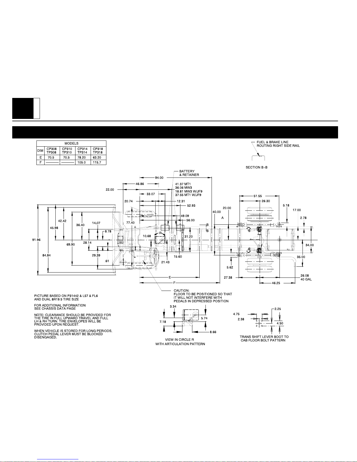
P 30042 General Arrangement, Diesel Engine, Option L57, 6.5L HO w/FL6 Independent Front Suspension
 Loading...