

Page 1
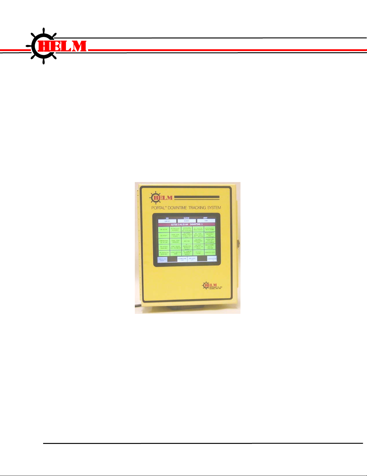
Portal Downtime System
Helm Instrument Company, Inc.
361 West Dussel Drive
Maumee, Ohio 43537 USA
419/ 893-4356
Fax: 419/ 893-1371
www.helminstrument.com
OPERATIONS MANUAL
Revision 1.1
© Helm Instrument Co., Inc, 2005
Page 1 of 28
Page 2
DOWNTIME
Portal Downtime System
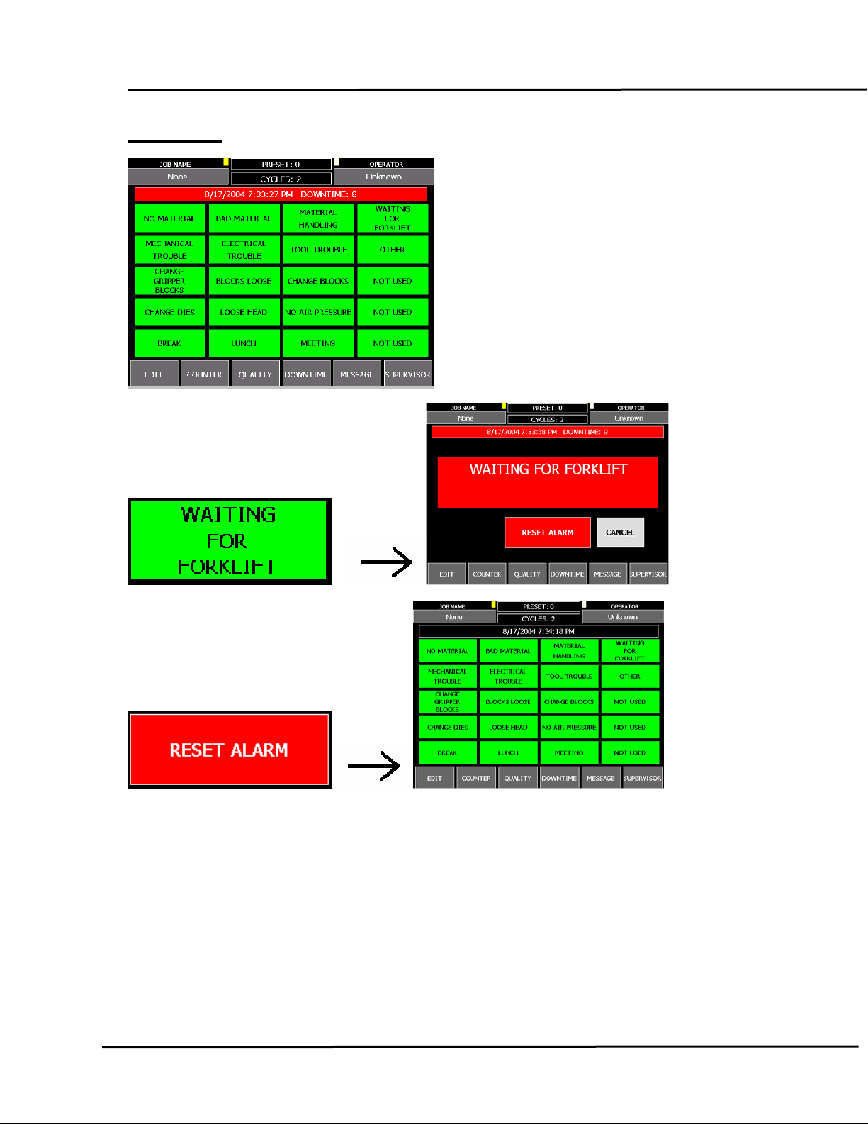
Report a DOWNTIME event by touching the
green Reason Button containing the desired
reason. This opens the DOWNTIME RESET
panel. Touch the red RESET ALARM button to
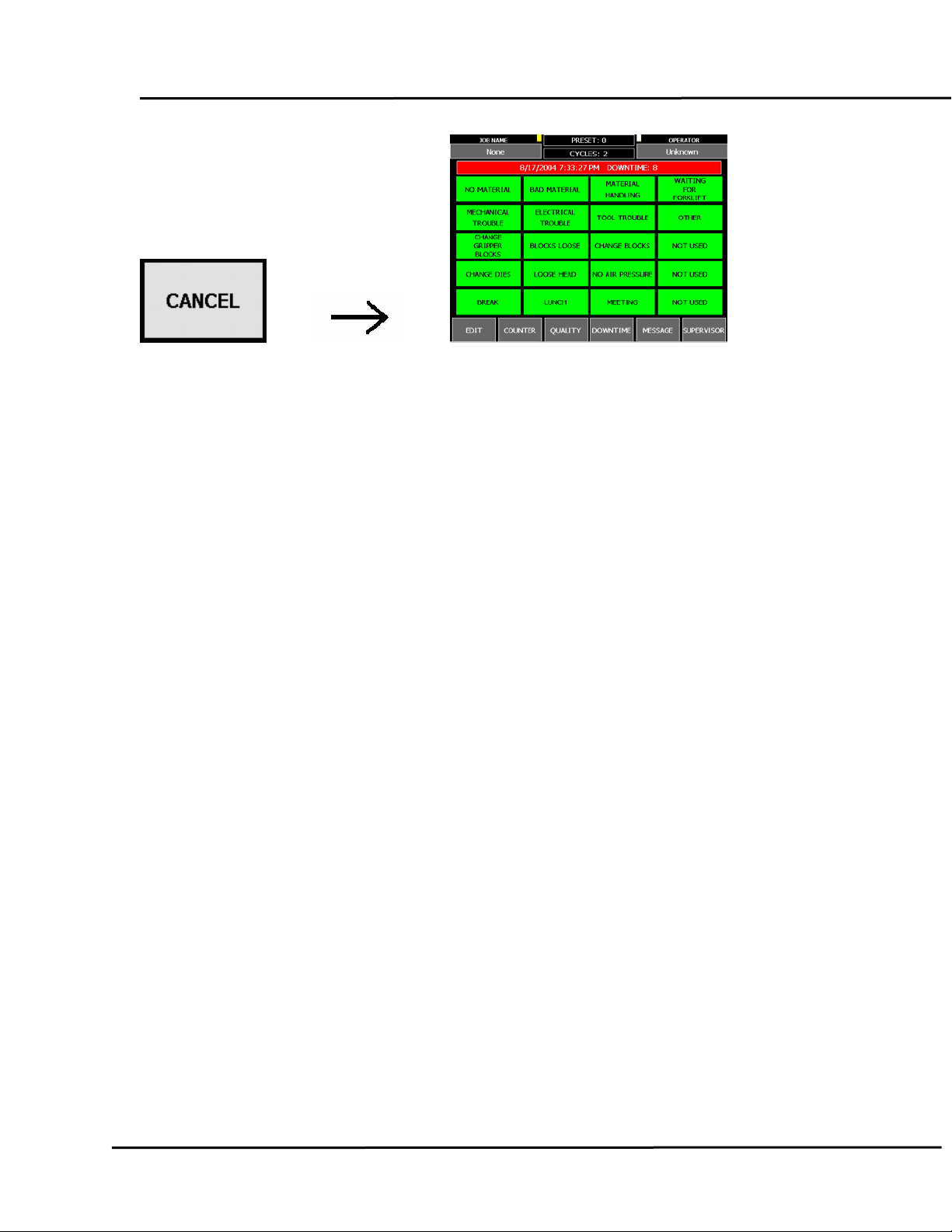
save this downtime event. Touch the grey
CANCEL button to close the panel without
saving the event.
Writes to Table: DOWNTIME
Page 2 of 28
Page 3
Portal Downtime System
Page 3 of 28
Page 4
JOB
Portal Downtime System
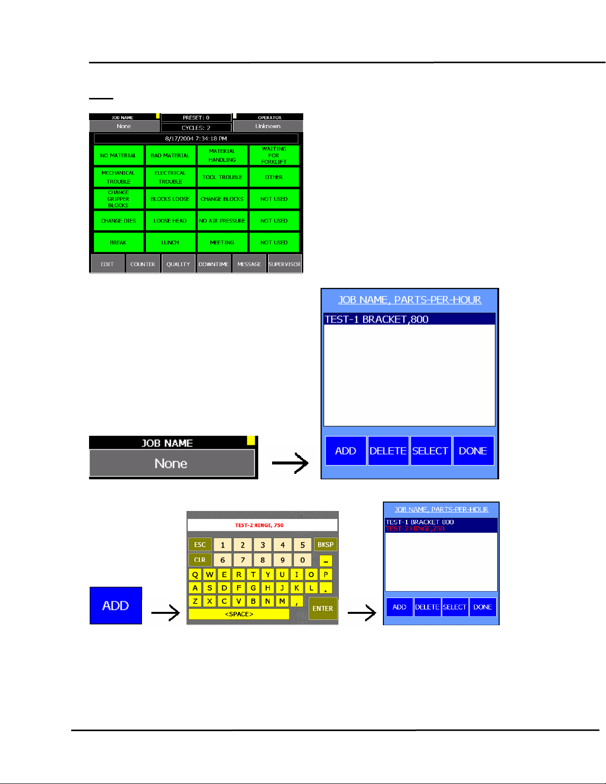
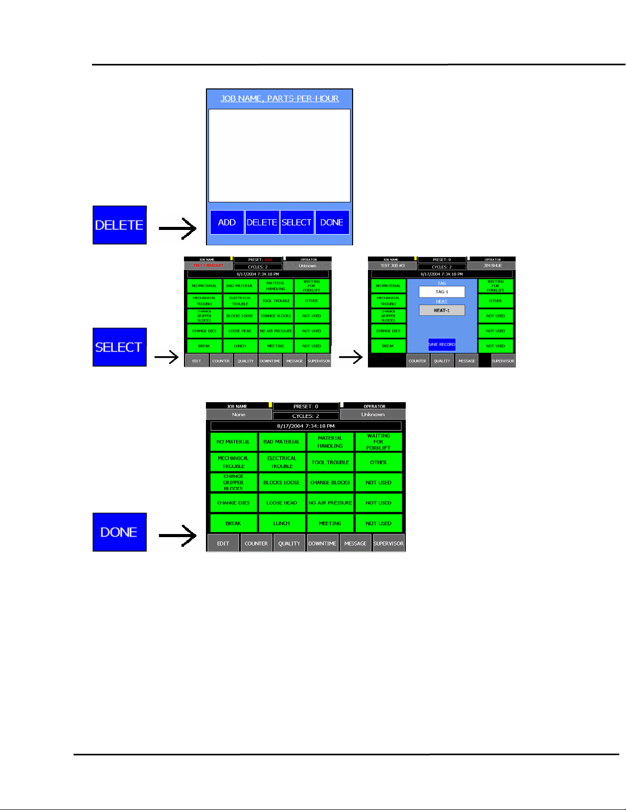
Touch the JOB NAME button to
display the JOB SELECTION panel.
Use ADD to create a job. Use
DELETE to remove a job. Activate a
job by choosing touching the desired
job name and then touching SELECT.
Touch the DONE button to close the
panel.
Page 4 of 28
Page 5
Portal Downtime System
Writes to Table: JOBHISTORY
Page 5 of 28
Page 6
OPERATOR
Portal Downtime System
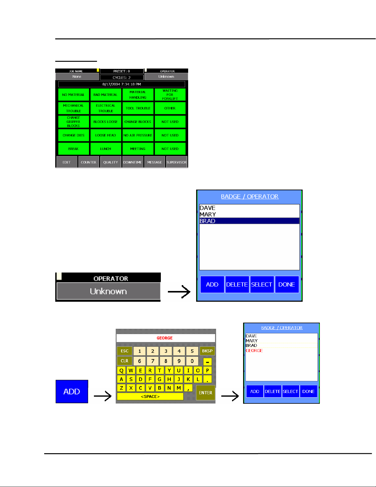
Touch the OPERATOR button to
display the OPERATOR SELECTION
panel. Use ADD to enter a new
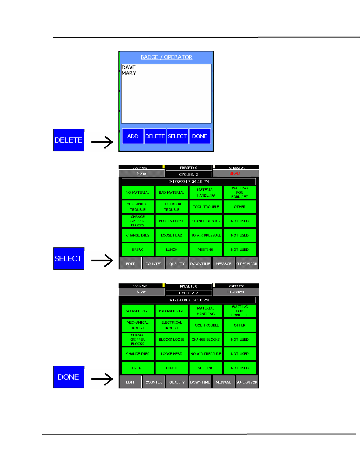
operator name. Use DELETE to
remove a name. Activate a new
operator by choosing touching the
desired name and then touching
SELECT. Touch the DONE button to
close the panel.
Page 6 of 28
Page 7
Portal Downtime System
Page 7 of 28
Page 8
Portal Downtime System
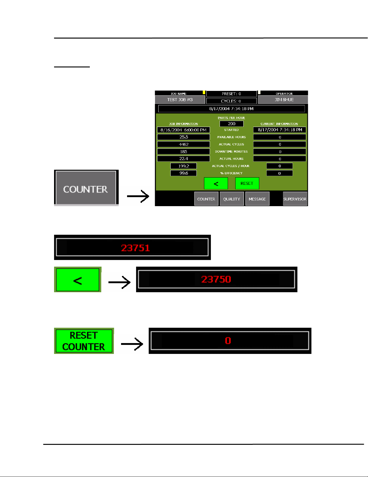
COUNTER
Touch the COUNTER button to display or hide the COUNTER panel.
Use the “<” button to decrease the Cycles Counter when desired.
Touching RESET zeros the Parts Counter and clears all CURRENT values.
Page 8 of 28
Page 9
Portal Downtime System
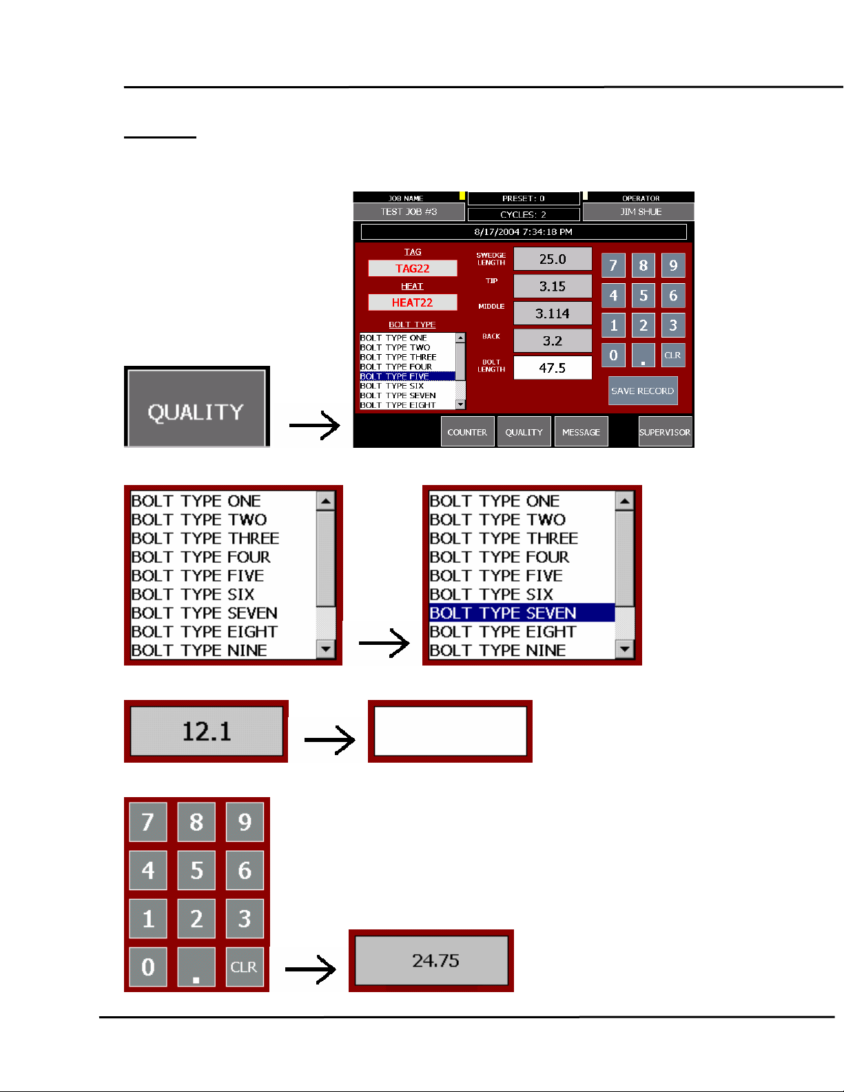
QUALITY
Touch the QUALITY button to display or hide the Quality Panel.
Touch the BOLT TYPE list to select a bolt name.
Touching a QUALITY button clears its value.
Use the KEYPAD to enter a new Quality Value.
Page 9 of 28
Page 10
Portal Downtime System
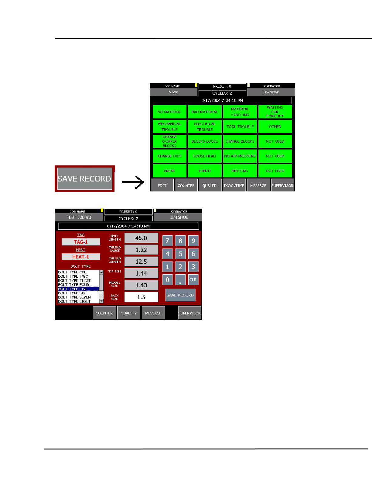
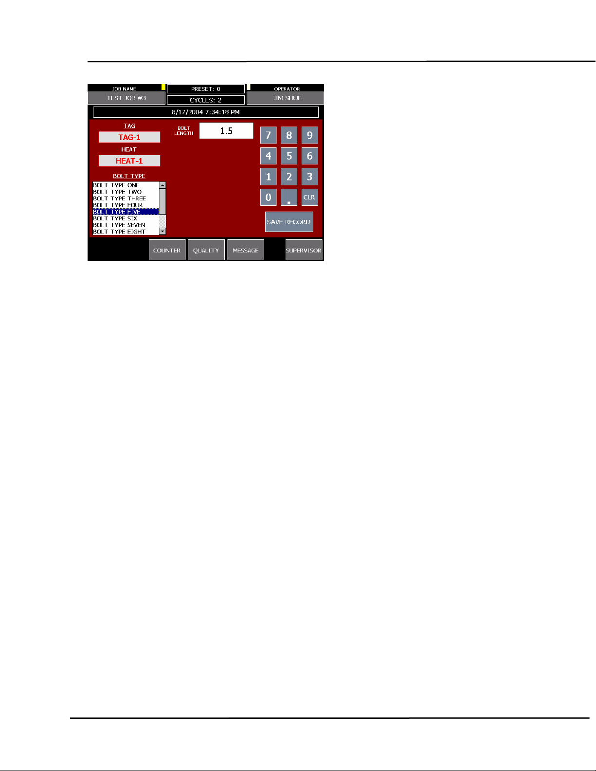
The SAVE RECORD button will record the Quality Record if all values have been
entered. You must complete all quality fields and select a Bolt Type.
THREADER
SHEAR
Page 10 of 28
Page 11
Portal Downtime System
Page 11 of 28
Page 12
Portal Downtime System
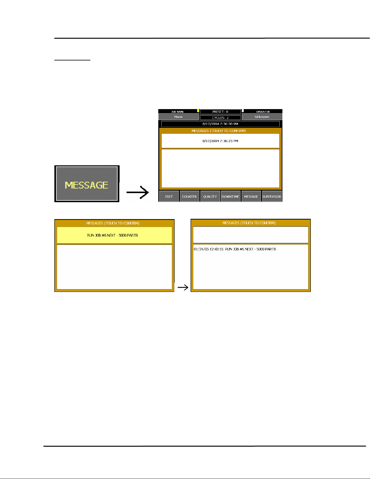
MESSAGE
Touch the MESSAGE button to display or hide the Message Panel. The
MESSAGE button will turn BROWN when a new message has been received. A
new message is displayed at the top of the panel and recent messages are
shown in on the lower display.
Touch the NEW MESSAGE to acknowledge it and move it to the list box.
Page 12 of 28
Page 13
Portal Downtime System
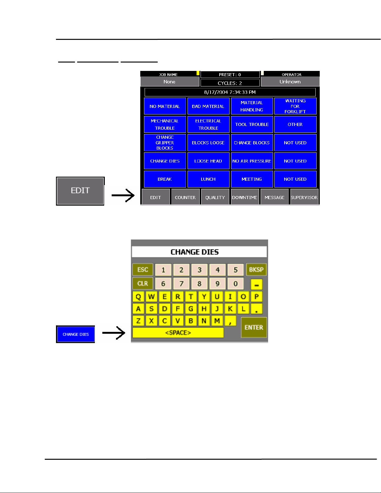
EDIT DOWNTIME REASONS
Touching the EDIT button, when visible, locks all other buttons, turns the
DOWNTIME REASON blue and allows you to edit the reasons.
Touch a blue downtime button to open the keyboard and enter the new reason.
Page 13 of 28
Page 14
Portal Downtime System
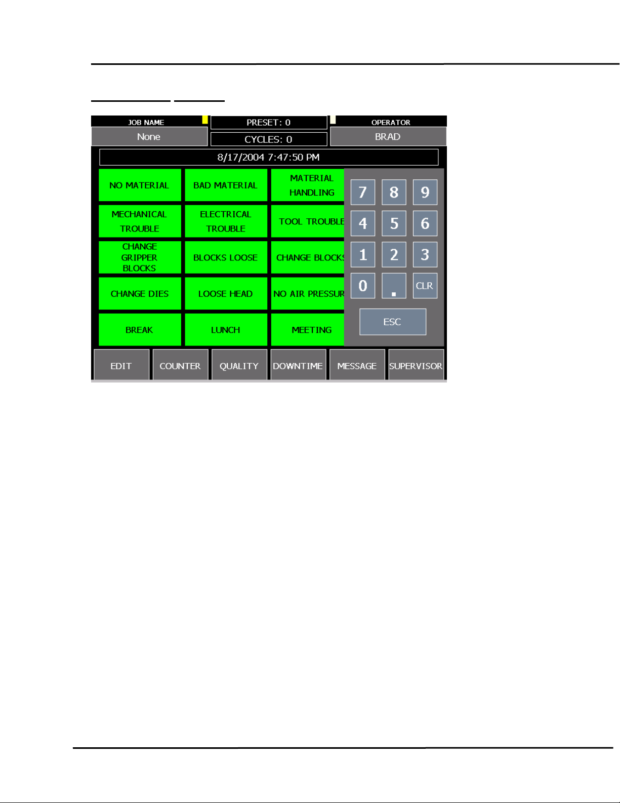
SUPERVISOR KEYPAD
Page 14 of 28
Page 15
Portal Downtime System
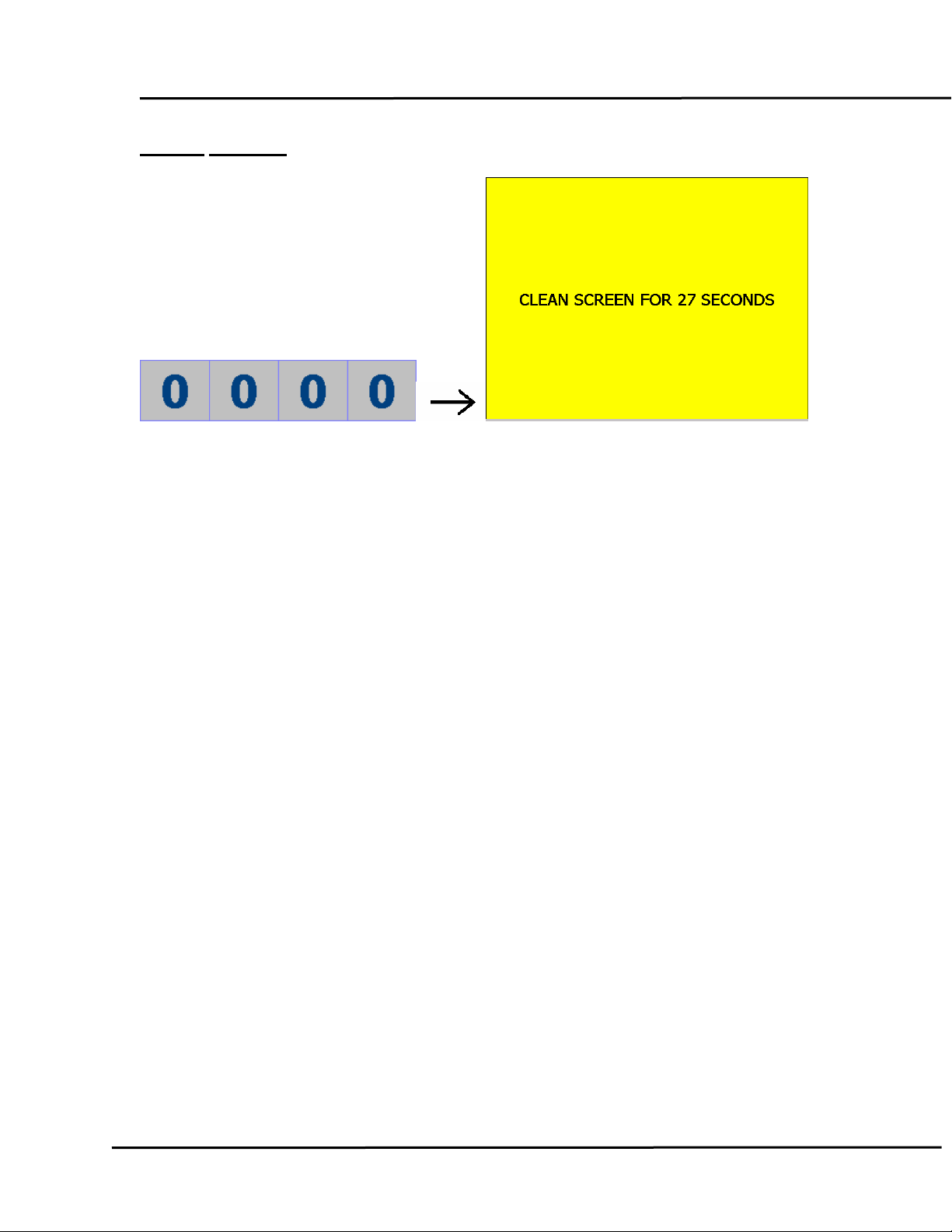
CLEAN SCREEN
Touch four zeros on the SUPERVISOR KEYPAD to open the CLEAN SCREEN
panel. This disables the Touch Screen and allows you to wipe off the screen
without pressing any buttons.
Page 15 of 28
Page 16
SUPERVISOR
Portal Downtime System
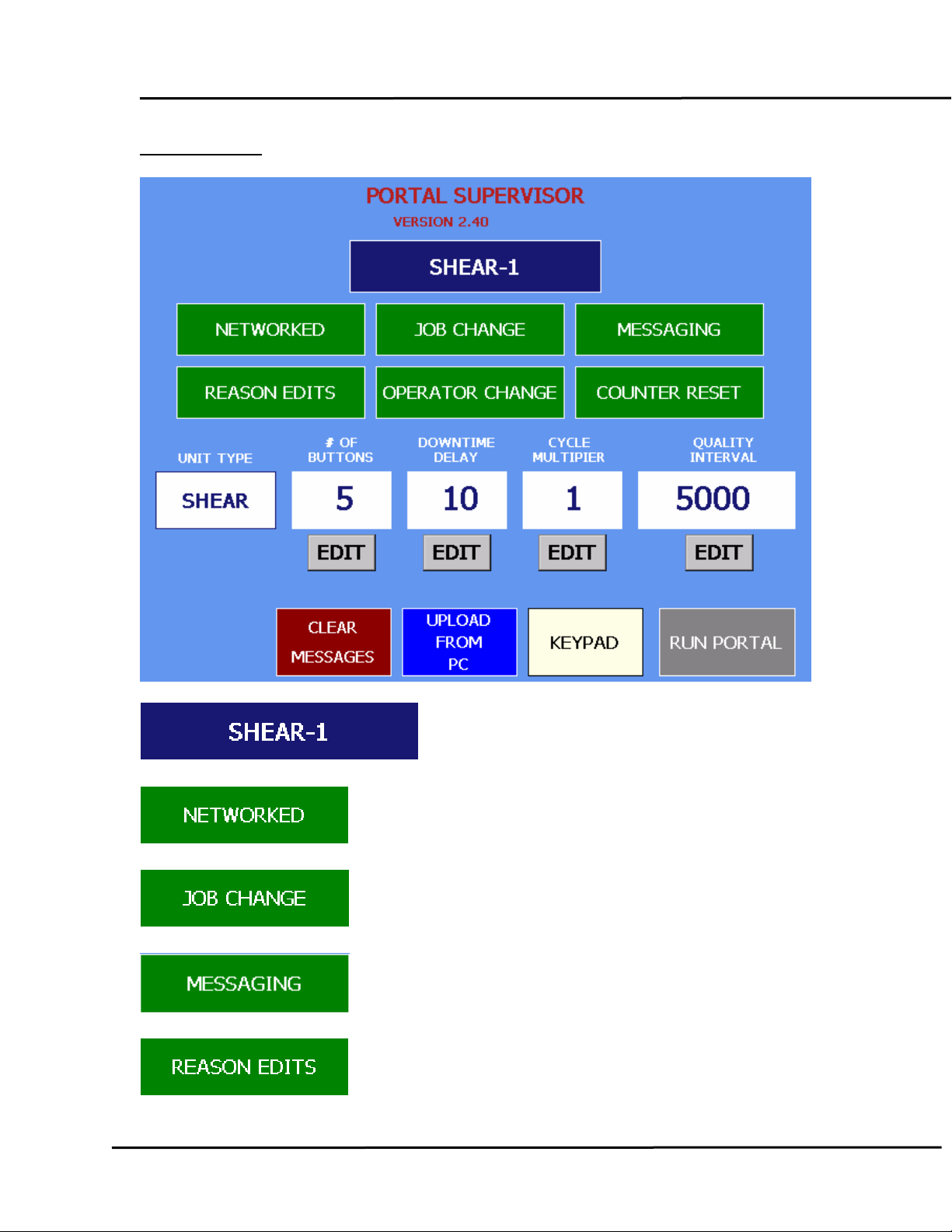
This button names the unit.
This button toggles network access.
Use this button to allow access to the Job Panel.
Use this button to allow access to the Message Panel.
Toggles access to the Reason Edit feature.
Page 16 of 28
Page 17
Portal Downtime System
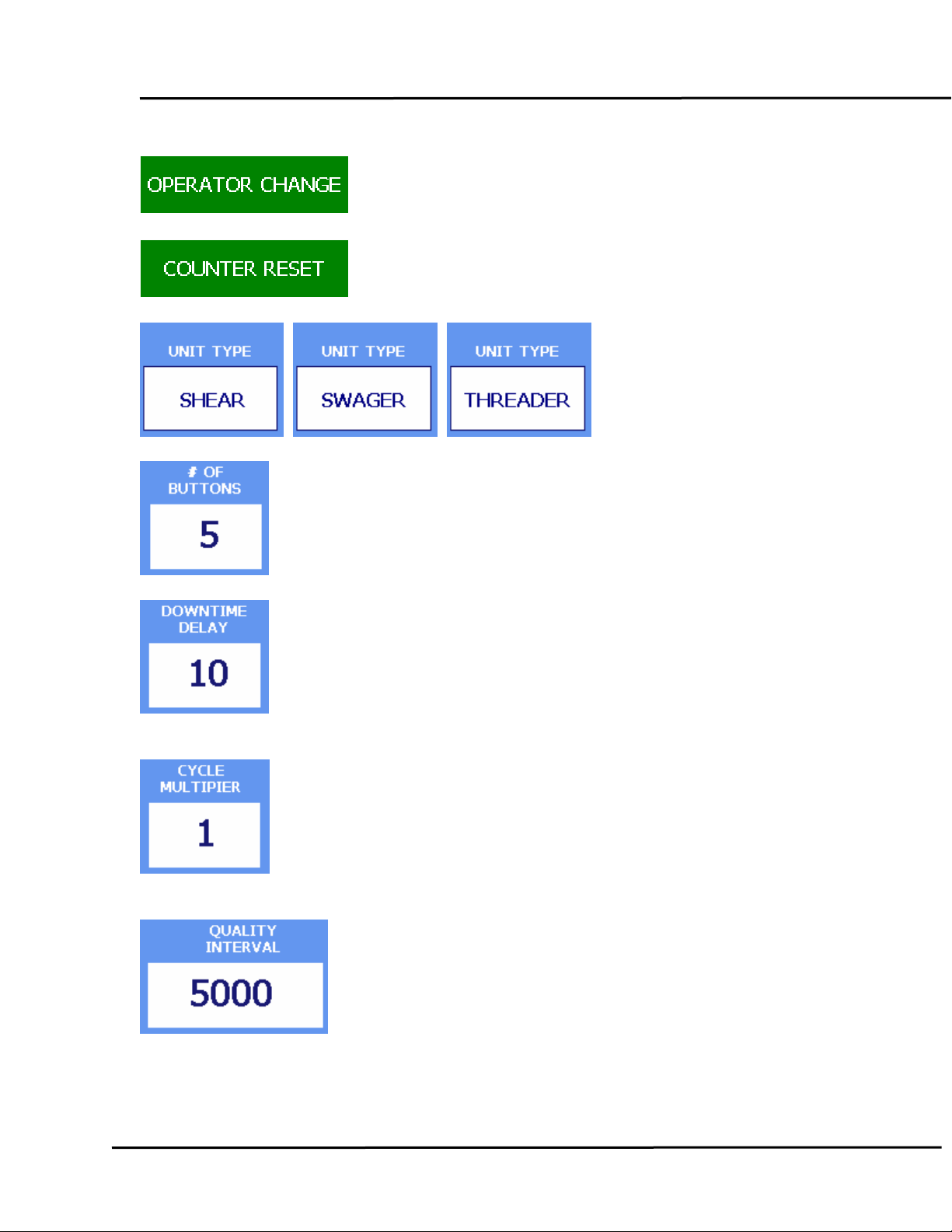
Use this button to allow access to the Operator Panel.
Toggles access to the Counter Reset button.
Selects Unit Type.
Selects the number of Reason buttons (multiples of five).
This sets the number of minutes of stoppage to wait before
initiating a Downtime Event.
The cycle count is multiplied by this factor to reflect true Parts
Count.
check.
This is the number of cycles to break on for a quality
Page 17 of 28
Page 18
Portal Downtime System
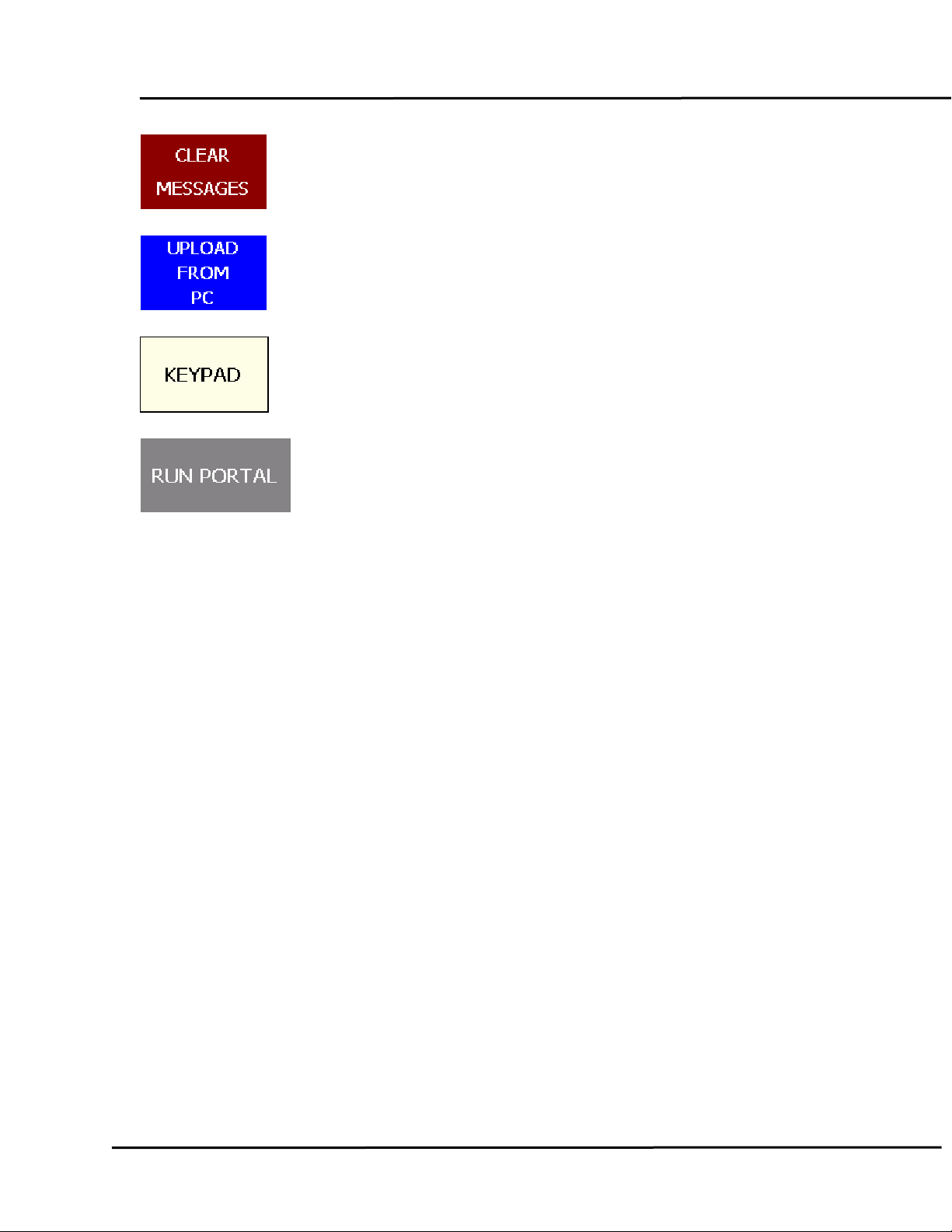
Clears the message log.
Uploads maintenance files from the PC.
Opens the keypad.
Returns to the Portal main screen.
Page 18 of 28
Page 19
Portal Downtime System
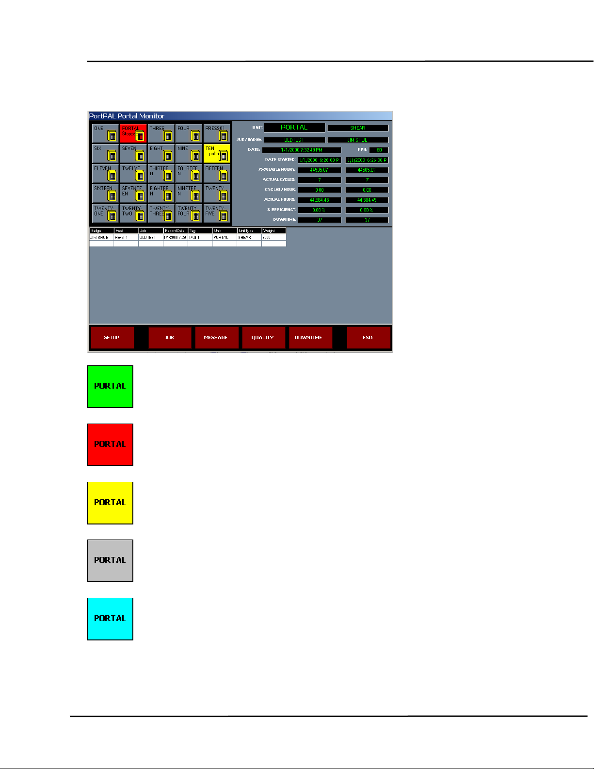
PORTPal: MAIN SCREEN
Unit is ACTIVE and RUNNING.
Unit is ACTIVE and DOWN.
Unit is being POLLED for status.
Unit is OFFLINE or INACTIVE
Communication has encountered an ERROR.
Page 19 of 28
Page 20
Portal Downtime System
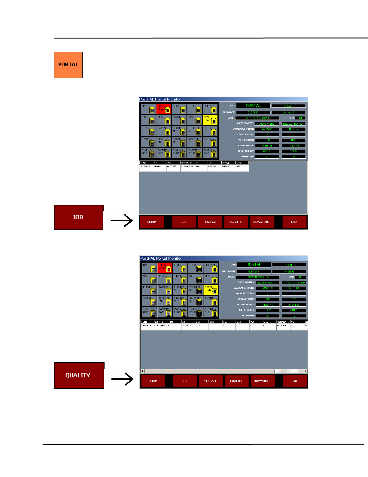
Unit’s CYCLE COUNT >= to 95% of BATCH PRESET.
PORTPal: JOB HISTORY
PORTPal: QUALITY
PORTPal: DOWNTIME
Page 20 of 28
Page 21
Portal Downtime System
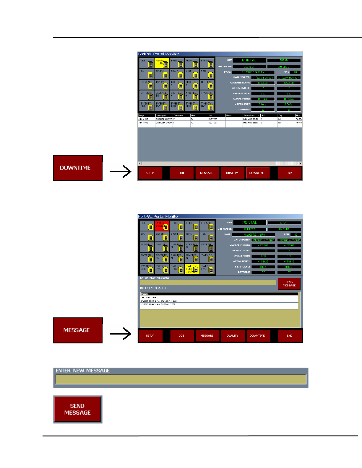
PORTPal: MESSAGE DISPLAY
Click on the Unit to send a message to.
Click on the Message Panel and type in the desired message.
Click SEND MESSAGE to route it to the selected unit.
Page 21 of 28
Page 22
Portal Downtime System
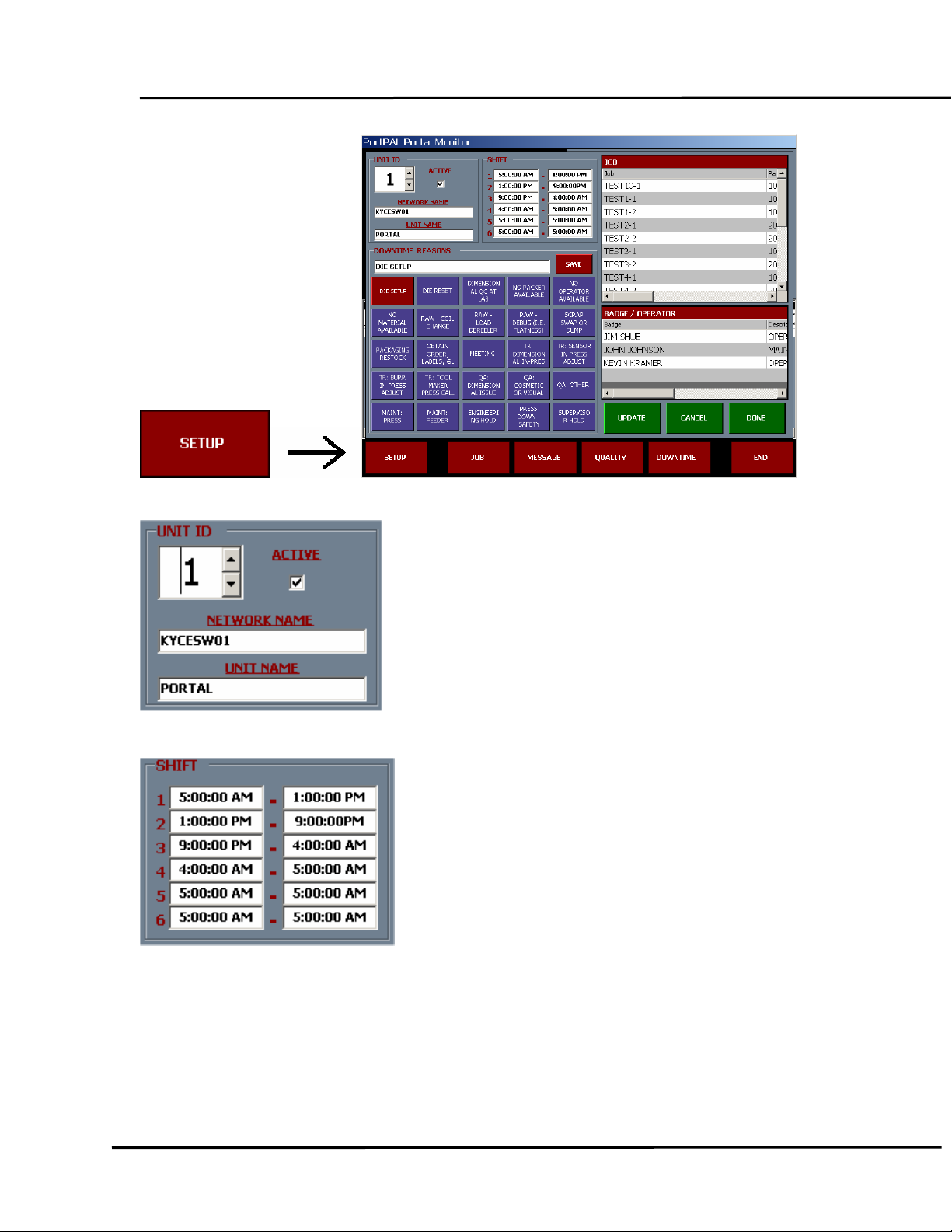
address. Toggle polling.
Select the unit by number. Name it or provide an IP
Edit shift times.
Page 22 of 28
Page 23
Portal Downtime System
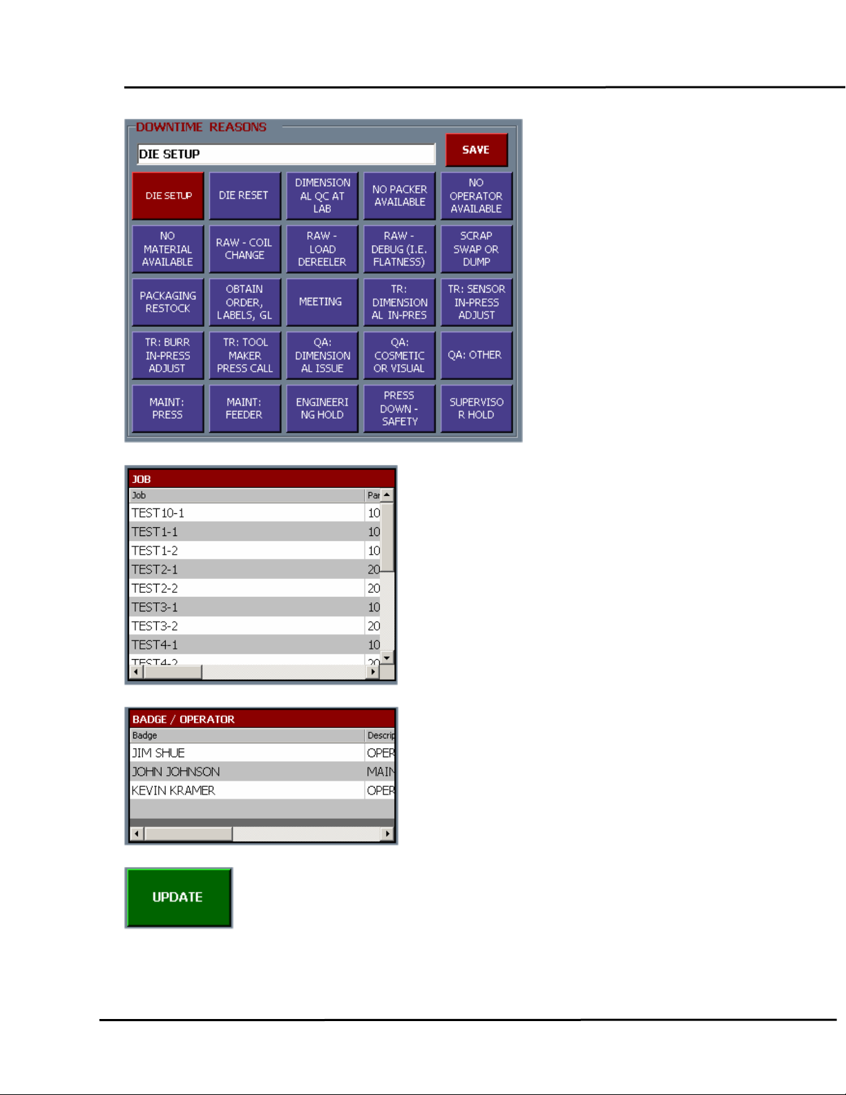
Edit downtime reasons.
Set up Jobs for download to each units.
List operators for each unit.
Commit pending changes.
Page 23 of 28
Page 24
Portal Downtime System
Cancel pending changes.
Close the SETUP panel and resume polling.
Page 24 of 28
Page 25
Portal Downtime System
Page 25 of 28
Page 26
Portal Downtime System
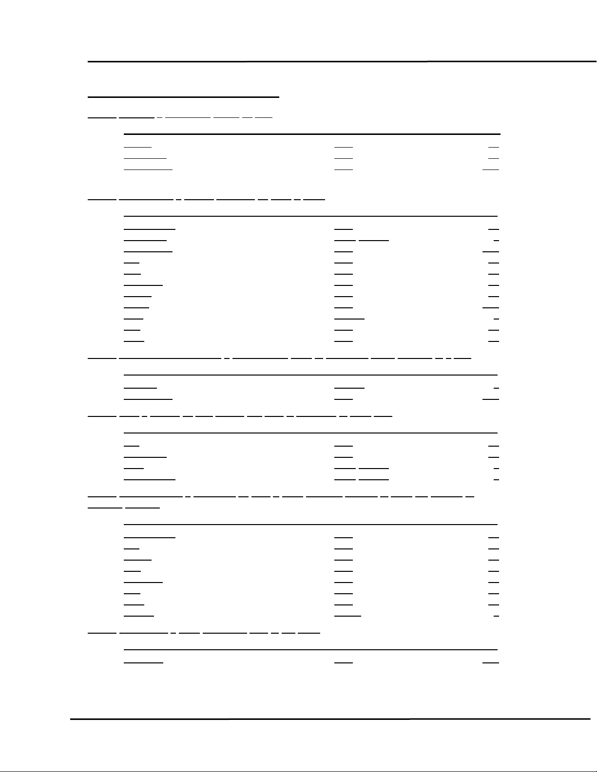
PORTAL DATABASE STRUCTURE
Table: BADGE – Operator’s Name by Unit
Badge
UnitName
Description
Table: DOWNTIME – Events recorded by Date & Time
RecordDate
Downtime Long Integer 4
Description
Job
Unit
UnitType
Badge
Notes Text 255
Shift
Tag
Heat Text 50
Name Type Size
Text 50
Text 50
Text 255
Name Type Size
Text 25
Text 255
Text 50
Text 35
Text 50
Text 35
Integer 2
Text 50
Table:
DOWNTIMEREASONS – Maintenance table or uploading event reasons to a Unit
Reason
Description
Table:
Job
UnitName
PPH
PartsToRun
Table:
material
RecordDate
Job
Badge
Unit
UnitType
Tag
Heat
Weight
Table:
Message
Name Type Size
Integer 2
Text 255
JOB – Tabled by Unit Name, this data is uploaded to each unit.
Name Type Size
Text 50
Text 50
Long Integer 4
Long Integer 4
JOBHISTORY – Recorded by date & time, contains records of each job change or
change.
Name Type Size
Text 50
Text 50
Text 35
Text 50
Text 50
Text 50
Text 50
Single 4
MESSAGE – Logs messages sent to the Units
Name Type Size
Text 255
Page 26 of 28
Page 27
Portal Downtime System
Table:
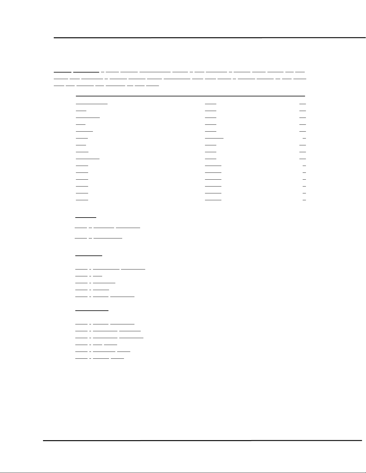
QUALITY – Logs quality information. When a unit reaches a preset cycle count, the unit
and requires a quality record entry. Operators may also enter a quality record at any time.
stops
The
QC values are defined by unit type.
RecordDate
Unit
UnitType
Job
Badge
Shift
Tag
Heat
BoltType
QC1
QC2 Single 4
QC3
QC4
QC5 Single 4
QC6
Name Type Size
Text 25
Text 35
Text 50
Text 50
Text 50
Integer 2
Text 50
Text 50
Text 50
Single 4
Single 4
Single 4
Single 4
SHEAR QC1 QC2
SWAGER QC1
QC2
QC3
QC4 - BACK
QC5
THREADER QC1
QC2
QC3
QC4
QC5
QC6
– SHEAR LENGTH
– BACKCUT
- SWEDGE LENGTH
- TIP
- MIDDLE
- BOLT LENGTH
- BOLT LENGTH
- THREAD GAUGE
- THREAD LENGTH
- TIP SIZE
- MIDDLE SIZE
- BACK SIZE
Page 27 of 28
Page 28
Portal Downtime System
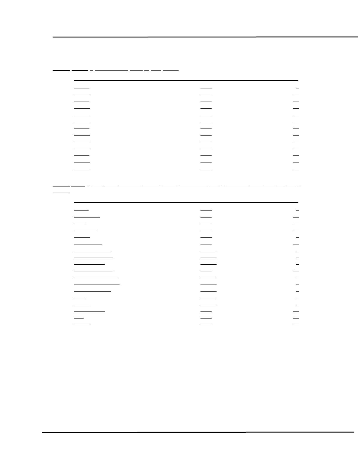
SHIFT – Maintenance table of shift times.
Table:
Prime
Start1
Stop1
Start2
Stop2
Start3
Stop3
Start4
Stop4
Start5
Stop5
Start6
Stop6
Table:
polled.
Na
Index Byte 1
Computer
Unit
UnitType Text 50
Active
JobStarted
TotalAvailable Single 4
TotalDowntime
TotalCycles
CurrentStarted Text 25
CurrentAvailable
CurrentDowntime
CurrentCycles
PPH
Batch
RecordDate
Job
Badge
Name Type Size
Byte 1
Text 11
Text 11
Text 11
Text 11
Text 11
Text 11
Text 11
Text 11
Text 11
Text 11
Text 11
Text 11
UNIT – This table contains current status information and is updated each time the unit is
me Type Size
Text 50
Text 50
Byte 1
Text 25
Single 4
Single 4
Single 4
Single 4
Single 4
Single 4
Single 4
Text 25
Text 50
Text 35
Page 28 of 28
 Loading...