

Page 1
9
4 5 3 6 2 8 7
10
1
Description
Description
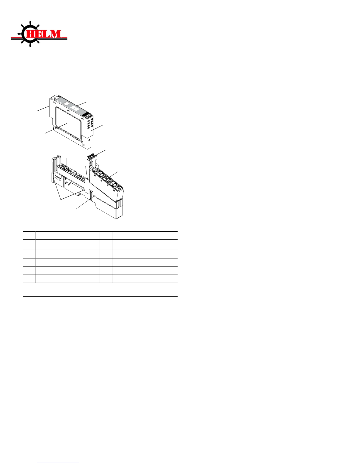
1 6 RTB Removal Handle
Mounting Base
1
2
Mechanical Keying (orange)
7
Removable Terminal Block (RTB)
1
3
Module Wiring Diagram
8
DIN Rail Locking Screw (orange)
4
Module Locking Mechanism
9
Slide-in Writable Label
5
Insertable I/O Module
10
Interlocking Side Pieces
1
Wiring Base Assembly consists of item 1) mounting base, 1734-MB and item 7) removable
terminal block, 1734-RT or -RTS.
POINT I/O is a trademark of Rockwell Automation1
DeviceNet is a trademark of ODVA, Inc.
Helm Instrument Company, Inc.
361 West Dussel Drive
Maumee, Ohio 43537 USA
419/ 893-4356
Fax: 419/ 893-1371
www.helminstrument.com
Installation Instructions
HM1734-WM-2HR
POINT I/O Strain Gage Input Module
2/11/2019
February, 2019
Page 2
2 HM1734-WM Strain Gage Input Module
This Series C product can be used with DeviceNet and PROFIBUS
adapters. It can be used with Ethernet/IP and Ethernet adapters using
RSLogix 5000, version 11 (or higher) software.
Important User Information
Because of the variety of uses for the products described in this publication,
those responsible for the application and use of these products must satisfy
themselves that all necessary steps have been taken to assure that each
application and use meet all performance and safety requirements, including
any applicable laws, regulations, codes and standards. In no event will
Allen-Bradley be responsible or liable for indirect or consequential damage
resulting from the use or application of these products.
Any illustrations, charts, sample programs, and layout examples shown in this
publication are intended solely for purposes of example. Since there are many
variables and requirements associated with any particular installation,
Allen-Bradley does not assume responsibility or liability (to include intellectual
property liability) for actual use based upon the examples shown in this
publication.
Allen-Bradley publication SGI-1.1, Safety Guidelines for the Application,
Installation and Maintenance of Solid-State Control (available from your local
Allen-Bradley office), describes some important differences between
solid-state equipment and electromechanical devices that should be taken into
consideration when applying products such as those described in this
publication.
Reproduction of the contents of this copyrighted publication, in whole or
part, without written permission of Rockwell Automation, is prohibited.
Throughout this publication, notes may be used to make you aware of safety
considerations. The following annotations and their accompanying statements
help you to identify a potential hazard, avoid a potential hazard, and recognize
the consequences of a potential hazard.
Identifies information about practices or
WARNING
circumstances that can cause an explosion in a
hazardous environment, which may lead to
!
personal injury or death, property damage, or
economic loss.
Page 3
3 HM1734-WM Strain Gage Input Module
Identifies information about practices or
ATTENTION
circumstances that can lead to personal injury or
death, property damage, or economic loss.
!
Identifies information that is critical for
IMPORTANT
successful application and understanding of the
product.
-
Page 4
4 HM1734-WM Strain Gage Input Module
Environment and Enclosure
ATTENTION
!
This equipment is intended for use in a Pollution Degree 2
industrial environment, in overvoltage Category II applications
(as defined in IEC publication 60664-1), at altitudes up to 2000
meters without derating.
This equipment is considered Group 1, Class A industrial
equipment according to IEC/CISPR Publication 11. Without
appropriate precautions, there may be potential difficulties
ensuring electromagnetic compatibility in other environments
due to conducted as well as radiated disturbance.
This equipment is supplied as "open type" equipment. It must
be mounted within an enclosure that is suitably designed for
those specific environmental conditions that will be present and
appropriately designed to prevent personal injury resulting from
accessibility to live parts. The interior of the enclosure must be
accessible only by the use of a tool. Subsequent sections of this
publication may contain additional information regarding
specific enclosure type ratings that are required to comply with
certain product safety certifications.
See NEMA Standards publication 250 and IEC publication
60529, as applicable, for explanations of the degrees of
protection provided by different types of enclosure. Also, see the
appropriate sections in this publication, as well as the
Allen-Bradley publication 1770-4.1 ("Industrial Automation
Wiring and Grounding Guidelines"), for additional installation
requirements pertaining to this equipment.
POINT I/O is grounded through the DIN rail to
ATTENTION
chassis ground. Use zinc plated, yellow chromated
!
steel DIN rail to assure proper grounding. Using
other DIN rail materials (e.g. aluminum, plastic,
etc.) which can corrode, oxidize or are poor
conductors can result in improper or intermittent
platform grounding.
Page 5
5 HM1734-WM Strain Gage Input Module
EXPLOSION HAZARD
WARNING
Do not disconnect equipment unless power has been
!
removed or the area is known to be nonhazardous.
Do not disconnect connections to this equipment unless
power has been removed or the area is known to be
nonhazardous. Secure any external connections that mate
to this equipment by using screws, sliding latches, threaded
connectors, or other means provided with this product.
Substitution of components may impair suitability for Class
I, Division 2.
If this product contains batteries, they must only be
changed in an area known to be nonhazardous.
Preventing Electrostatic Discharge
ATTENTION
This equipment is sensitive to electrostatic
!
discharge, which can cause internal damage and
affect normal operation. Follow these guidelines
when you handle this equipment:
Touch a grounded object to discharge potential
static.
Wear an approved grounding wriststrap.
Do not touch connectors or pins on component
boards.
Do not touch circuit components inside the
equipment.
If available, use a static-safe workstation.
When not in use, store the equipment in
appropriate static-safe packaging.
Page 6
6 HM1734-WM Strain Gage Input Module
Installing the Mounting Base
To install the mounting base on the DIN rail, proceed as follows.
1. Position the mounting base vertically above the installed units
(adapter, power supply or existing module.
2. Slide the mounting base down allowing the interlocking side pieces to
engage the adjacent module or adapter.
3. Press firmly to seat the mounting base on the DIN rail. The mounting
base will snap into place.
4. To remove the mounting base from the DIN rail, remove the module,
and use a small bladed screwdriver to rotate the base locking screw to
a vertical position. This releases the locking mechanism. Then lift
straight up to remove.
Installing the I/O Module
The module can be installed before, or after base installation. Make sure that
the mounting base is correctly keyed before installing the module into the
mounting base. In addition, make sure the mounting base locking screw is
positioned horizontal referenced to the base.
When you insert or remove the module while
WARNING
backplane power is on, an electrical arc can
!
occur. This could cause an explosion in
hazardous location installations. Be sure that
power is removed or the area is nonhazardous
before proceeding.
1. Using a bladed screwdriver, rotate the keyswitch (2) on the
mountingbase clockwise until the number required for the type of
module being installed aligns with the notch in the base.
2. Make certain the DIN rail locking screw is in the horizontal position.
(You cannot insert the module if the locking mechanism is unlocked.)
Page 7
7 HM1734-WM Strain Gage Input Module
3. Insert the module straight down into the mounting base and press to
secure. The module will lock into place.
Installing the Removable Terminal Block (RTB)
A removable terminal block is supplied with your wiring base assembly. To
remove, pull up on the RTB handle. This allows the mounting base to be
removed and replaced as necessary without removing any of the wiring. To
reinsert the removable terminal block, proceed as follows.
1. Insert the end opposite the handle into the base unit. This end has a
curved section that engages with the wiring base.
2. Rotate the terminal block into the wiring base until it locks itself in
place.
3. If an I/O module is installed, snap the RTB handle into place on the
module.
When you connect or disconnect the Removable
WARNING
Terminal Block (RTB) with field side power
applied, an electrical arc can occur. This could
!
cause an explosion in hazardous location
installations.
Be sure that power is removed or the area is
nonhazardous before proceeding.
Page 8

8 HM1734-WM Strain Gage Input Module
Removing a Mounting Base
To remove a mounting base, you must remove any installed module, and the
module installed in the base to the right. Remove the removable terminal
block (if wired).
1. Unlatch the RTB handle on the I/O module.
2. Pull on the RTB handle to remove the removable terminal block.
When you connect or disconnect the Removable
WARNING
Terminal Block (RTB) with field side power
applied, an electrical arc can occur. This could
!
cause an explosion in hazardous location
installations.
Be sure that power is removed or the area is
nonhazardous before proceeding.
3. Press on the module lock on the top of the module.
4. Pull on the I/O module to remove from the base.
When you insert or remove the module while
WARNING
backplane power is on, an electrical arc can
occur. This could cause an explosion in
!
hazardous location installations. Be sure that
power is removed or the area is nonhazardous
before proceeding.
5. Repeat steps 1, 2, 3 and 4 for the module to the right.
6. Use a small bladed screwdriver to rotate the orange base locking
screw to a vertical position. This releases the locking mechanism.
7. Then lift straight up to remove.
Page 9

9 HM1734-WM Strain Gage Input Module
OUTPUT TAG DESCRIPTIONS
CALMODE
Used for initial installation. All math is disabled, weigh value is not scaled, leaving raw A/D value.
Value = 2,090,000 to 2,100,000 at normal zero (at rest state).
RUNMODE
A/D values scaled with math in ladder logic
Factory cal setting 100,000 counts = 2MV/V
CLEAR TARE CH1/CH2 Bit
Clears internal tare value for “zero state”.
Useful when troubleshooting load cell wiring or other failures.
TARE CH1/CH2
Sets A/D value to zero.
READ ADTRIM BIT
(HELM Factory setting only).
SET-TO-CH1 Bit
Used for one channel operation where a faster sample speed is required.
1 = 2msec (max speed)
0 = 4msec (max speed-default)
FREQUENCY BITS
Used to set sample rate and filter options.
With no bits set: Sample = 100msec.
Set one bit only.
Note: For one channel operation, sample rate is at bit selected.
For two channel operation, sample rate is 2 times bit time selected.
Page 10

10 HM1734-WM Strain Gage Input Module
OUTPUT TAG DESCRIPTIONS
VIBRATION FILTER
Filter ON/OFF Bit
0 = Normal Average
1 = Rolling Average
MSF BITS – (Motion Stabilization Filter)
Used for applications with constant or static type loads to keep display value stable.
MSF1_2 (1 count up – 2 counts down).
MSF2_4
MSF4_8
MSF5_10
Set one bit only.
ZERO-DEAD-BAND Bits
Useful for Auto-Tare functions with production runs.
Set only one bit.
ZEROBAND_025 = .025% full scale
ZEROBAND_05 = .05% full scale
ZEROBAND_075 = .075% full scale
Auto tare occurs when load cell weight is at bit level or lower.
SET AVERAGE SAMPLE Bits
See Required Controller Tags:
HM1734WM1_a[8]
Page 11

11 HM1734-WM Strain Gage Input Module
REQUIRED CONTROLLER TAGS
CH1/CH2 SCALE SET
HM1734WM1_a[0]
HM1734WM1_a[3]
Full scale setting for CH1, CH2
Value is determined by capacity of load cell and by resolution required.
Example: 10KG = 10,000
SET AUTOCAL REFERENCE WEIGH VALUE CH1, CH2
HM1734WM1_a[1]
HM1734WM1_a[4]
Enter desired value to read based on known weight from calibrate procedure.
GET WEIGH VALUE CH1, CH2
HM1734WM1_a[2]
HM1734WM1_a[5]
Reports measured weigh value in RUN mode.
Reports raw A/D count value in CAL mode.
SET AUTOCAL CH1, CH2 Enable Bit
HM1734WM1_a[6]
HM1734WM1_a[7]
With ladder logic provided, an auto-cal method for calibrating is available.
Set to (1) to initiate Auto-Cal for the channel.
Ladder logic will clear the bit.
SET AVERAGE SAMPLE COUNT
HM1734WM1_a[8]
Set number of samples to take for average type filter.
Two Channel operation; Max value (50).
One Channel operation; Max value (100).
SET mV/V CH1, CH2
HM1734WM1_b[0]
HM1734WM1_b[1]
CH1/CH2 MV_V Settings
Enter 2.0MV/V for nominal load cell.
Actual value is from load cell specification.
AUTO CAL mV/V
HM1734WM1_b[2]
HM1734WM1_b[3]
Values generated by Auto_Cal routine.
Page 12
12 HM1734-WM Strain Gage Input Module
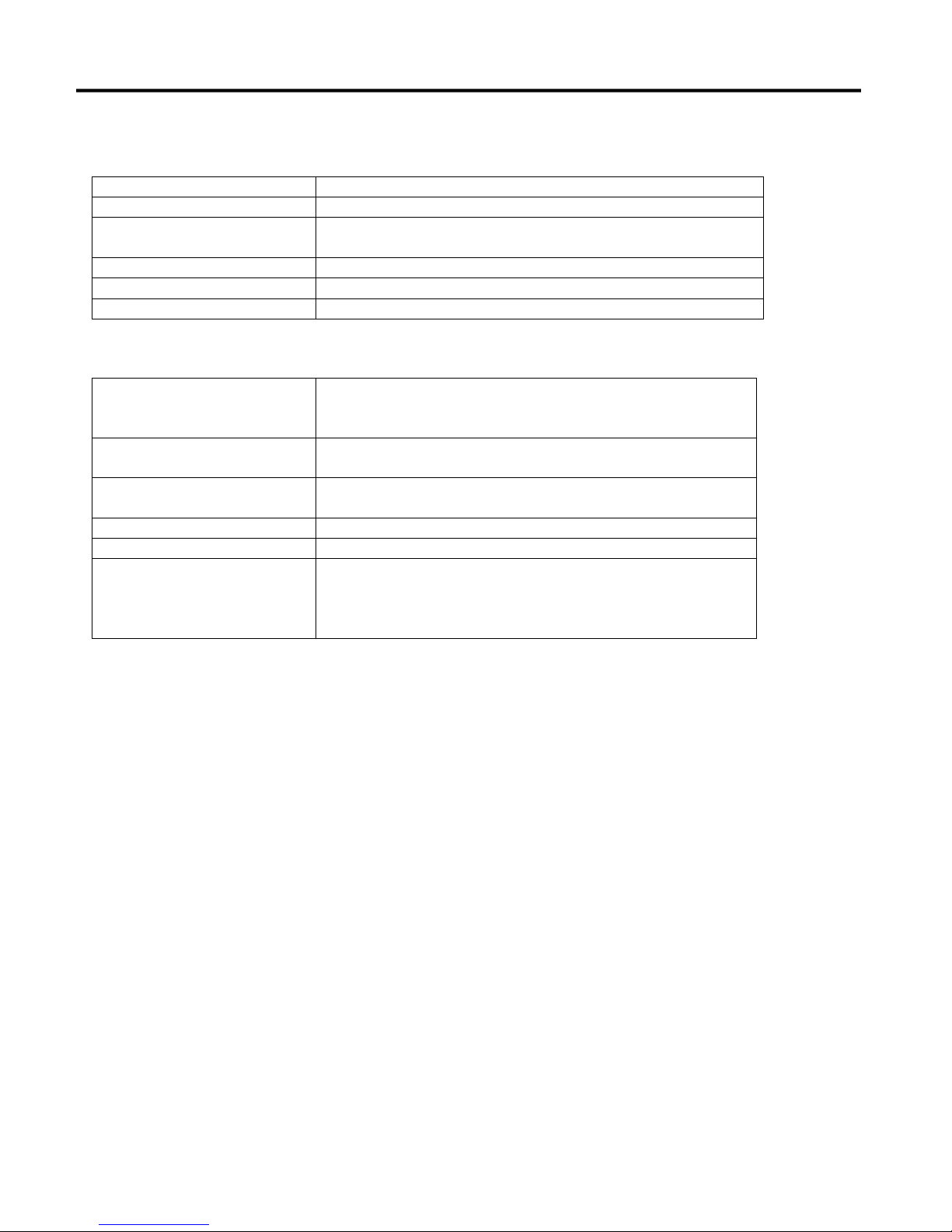
Off
No power applied to device.
Green
Device operating normally.
Flashing Green
Device needs commissioning due to configuration
missing, incomplete or incorrect.
Flashing Red
Recoverable fault.
Red
Unrecoverable fault. May require device replacement.
Flashing Red/Green
Device is in self-test.
Off
Device is not on-line. Device has not completed
dup_MAC_id test. Device not powered. Check module
status indicator.
Green
Device on-line and has connections to the established
state.
Flashing Green
Device is on-line but has no connections in the
established state.
Flashing Red
One or more I/O connections is in timed-out state.
Red
Critical link failure – failed communications device.
Flashing Red/Green
Network access error and is in communication faulted
state. Device has received and accepted an Identity
Communication Faulted Request – long protocol
message.
Troubleshooting with the Indicators
Module Status:
Network Status:
Page 13

13 HM1734-WM Strain Gage Input Module
Specifications - HM1734-WM Strain Gage Input Module
Setup Procedure
A complete listing of a sample ladder logic program is included
at the back of this manual.
Examples shown here are for reference.
All values are 0 (default) on initial start-up.
This means that all alarms are disabled.
You must make the following adjustments for proper operation:
Balance sensor input(s)
Set Calibration numbers
Follow Steps 1 and 2 for each channel.
Step 1. Balance Sensor Input Check
1. Set to CAL mode.
2. Set Clear Tare bit momentarily.
3. Check Raw A/D value. (Range 2,090,000 to 2,100,000)
CH1 = Controller Tag HM1734WM1-a[2]
CH2 = Controller Tag HM1734WM1-a[5]
4. Set Zero Tare bit momentarily.
Step 2. Set Calibration Numbers
1. Set Scale to capacity of load cell.
2. Set mV/V to load cell specification.
Example:
100 ton load cell, 2.025 mV/V
For scale set, enter 100
For mV/V set, enter 2.025
3. Set to RUN mode.
14 HM1734-WM Strain Gage Input Module
Page 14

15 HM1734-WM Strain Gage Input Module
CALIBRATING WITH KNOWN LOAD (AUTO-CAL)
1) Set known weight for channel at scale parameter.
2) Set mV/V.
3) Tare-0 (with no weight on cell/scale).
4) Set module to AUTOCAL mode (BIT).
5) Apply known load (test weight) to load cells/ scale.
6) Set AUTOCAL bit on for CH1 (CH2 if applicable).
7) To ensure accuracy repeat the steps above.
8) Toggle “SAVE TO EEPROM” (BIT).
9) MAKE SURE AUTOCAL MODE BIT STAYS ON.
Page 15
16 HM1734-WM Strain Gage Input Module
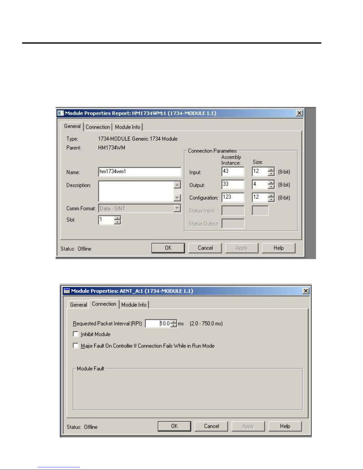
SETTING UP HM1734WM MODULE USING 1734-AENT/A on Ethernet/IP
Step #1
Add module to project as following:
HM1734WM MODULE PROPERTIES
General Tab Settings
Connection Tab Settings
Page 16

17 HM1734-WM Strain Gage Input Module
Step #2
Open “Template” file
Copy all controller tags
Open project file
Paste controller tags
Duplicates may be created, delete them now
Step #3
Open “Template” file
Copy add-on instruction “HM1734WM”
Open project file
Paste add-on instruction in add-on’s section
Page 17
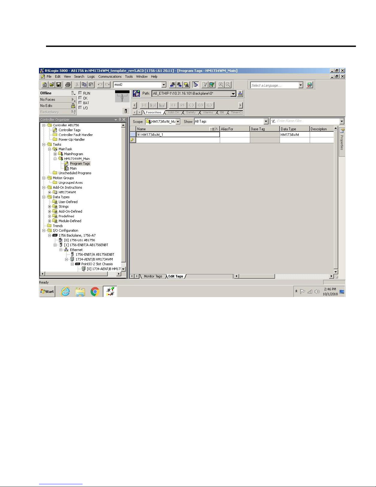
18 HM1734-WM Strain Gage Input Module
Step #4
Open “Template” file
Copy HM1734WM_main routine
Open project
Paste HM1734WM_main routine
Check program tag here should be as
Example
Page 18
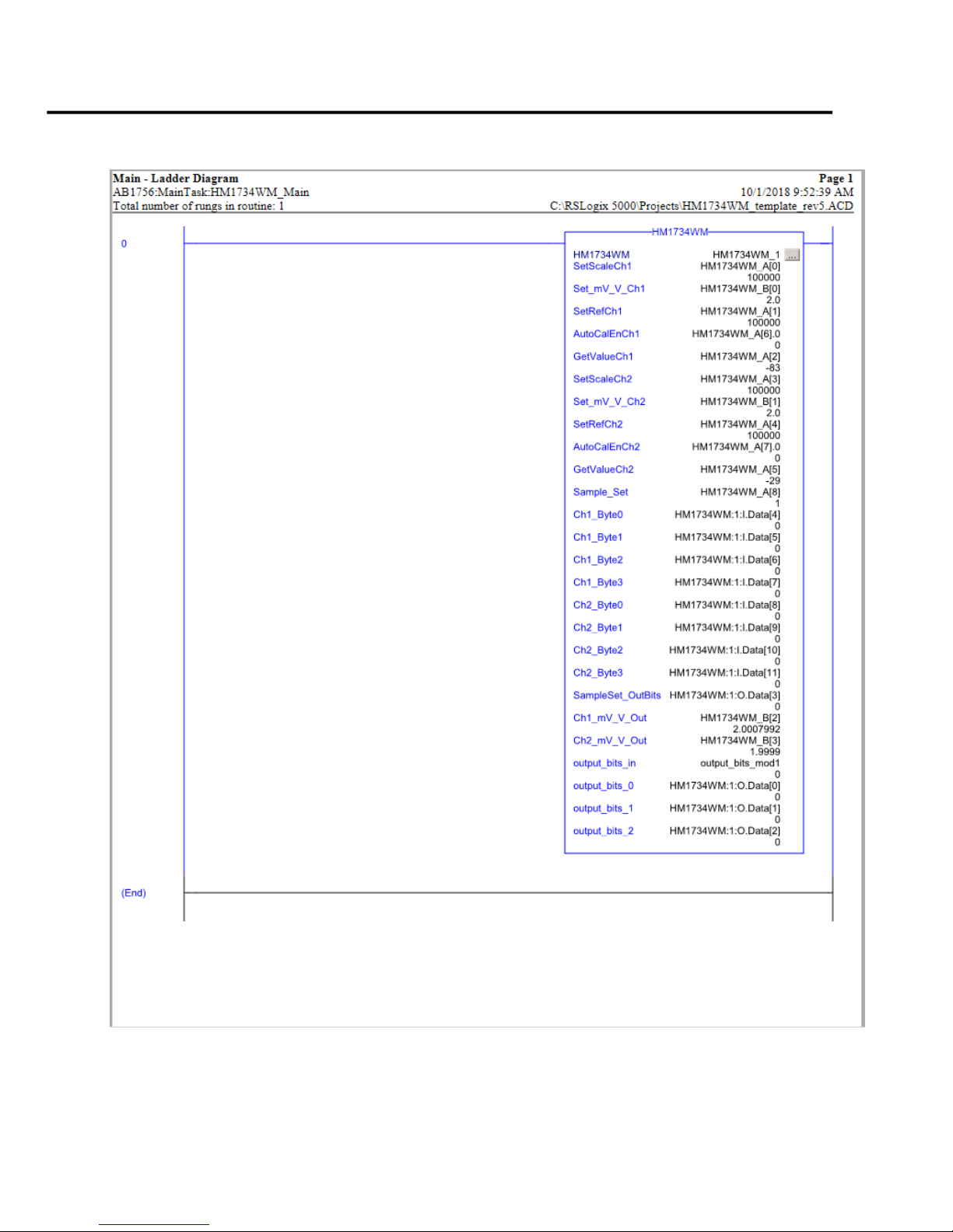
19 HM1734-WM Strain Gage Input Module
Step #5
Check routine for entries
Page 19
20 HM1734-WM Strain Gage Input Module
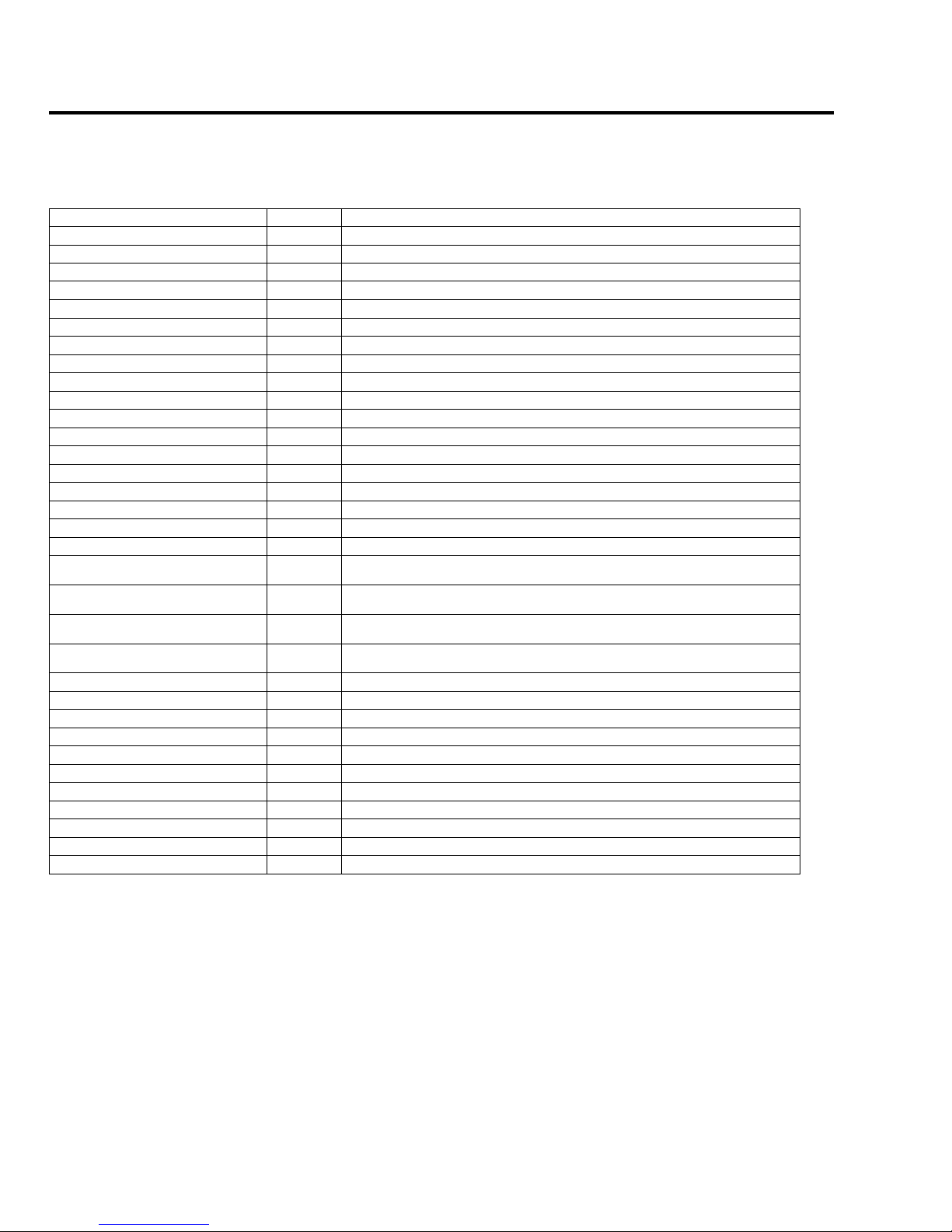
[n] = slot number for module
AENT_A:[n]:O.Data
SINT[4]
Description
Output_bits_mod1.0
bit
Set Cal Mode Bit
Output_bits_mod1.1
bit
Set Run Mode Bit
Output_bits_mod1.2
bit
Ch1 Clear Tare Bit (momentary)
Output_bits_mod1.3
bit
Ch1 Tare Bit (momentary)
Output_bits_mod1.4
bit
Reserved
Output_bits_mod1.5
bit
Read AD Trim Bit (Factory Use Only)
Output_bits_mod1.6
bit
Ch2 Clear Tare Bit (momentary)
Output_bits_mod1.7
bit
Ch2 Tare Bit (momentary)
Output_bits_mod1.8
bit
Reserved
Output_bits_mod1.9
bit
Set ch1_only
Output_bits_mod1.10
bit
Set_to_4ms (Frequency)
Output_bits_mod1.11
bit
Set_to_8ms (Frequency)
Output_bits_mod1.12
bit
Set_to_16ms (Frequency)
Output_bits_mod1.13
bit
Set_to_32ms (Frequency)
Output_bits_mod1.14
bit
Set_to_40ms (Frequency)
Output_bits_mod1.15
bit
Set_to_48ms (Frequency)
Output_bits_mod1.16
bit
Vibration Filter Bit
Output_bits_mod1.17
bit
Set Motion Stabilization Filter (MSF) range from -0.002% to +0.001% of full
scale
Output_bits_mod1.18
bit
Set Motion Stabilization Filter (MSF) range from -0.004% to +0.002% of full
scale
Output_bits_mod1.19
bit
Set Motion Stabilization Filter (MSF) range from -0.008% to +0.004% of full
scale
Output_bits_mod1.20
bit
Set Motion Stabilization Filter (MSF) range from -0.010% to +0.005% of full
scale
Output_bits_mod1.21
bit
Set Zero Dead Band to 0.025% of full scale
Output_bits_mod1.22
bit
Set Zero Dead Band to 0.05% of full scale
Output_bits_mod1.23
bit
Set Zero Dead Band to 0.075% of full scale
Output_bits_mod1.24
bit
Average Sample_bit0
Output_bits_mod1.25
bit
Average Sample_bit1
Output_bits_mod1.26
bit
Average Sample_bit2
Output_bits_mod1.27
bit
Average Sample_bit3
Output_bits_mod1.28
bit
Average Sample_bit4
Output_bits_mod1.29
bit
Average Sample_bit5
Output_bits_mod1.30
bit
Average Sample_bit6
Output_bits_mod1.31
bit
Average Sample_bit7
Data Map for HM1734-WM on Ethernet/IP
OUTPUT TAGS
Page 20
21 HM1734-WM Strain Gage Input Module
Data Tags Name
Data
Type
HM1734WM1
DINT[9]
HM1734WM1_A[0]
DINT
CH1 Set Scale Value
HM1734WM1_A[1]
DINT
CH1 Set AutoCal Reference Weigh Actual Value
HM1734WM1_A[2]
DINT
CH1 Get Weigh Value
HM1734WM1_A[3]
DINT
CH2 Set Scale Value
HM1734WM1_A[4]
DINT
CH2 Set AutoCal Reference Weigh Actual Value
HM1734WM1_A[5]
DINT
CH2 Get Weigh Value
HM1734WM1_A[6]
DINT
CH1 Set AutoCal Enable Bit
HM1734WM1_A[7]
DINT
CH2 Set AutoCal Enable Bit
HM1734WM1_A[8]
DINT
Set Average Sample Count (0-255)
HM1734WM1b
REAL[2]
HM1734WM1_B[0]
REAL
CH1 Set mV_V
HM1734WM1_B[1]
REAL
CH2 Set mV_V
HM1734WM1_B[2]
REAL
Ch1_Autocal_mV/V
HM1734WM1_B[3]
REAL
Ch2_Autocal_mV/V
Data Map for HM1734-WM on Ethernet/IP
Required Controller Tags
Page 21
22 HM1734-WM Strain Gage Input Module
Page 22
23 HM1734-WM Strain Gage Input Module
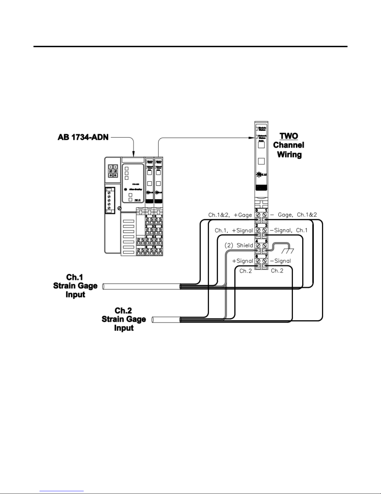
Helm HM-1734-WM
4-Wire Weigh Cell Connection
Page 23

24 HM1734-WM Strain Gage Input Module
Common
Techniques
Used in this
Manual
Product
Support
The following conventions are used throughout this manual:
Bulleted lists such as this one provides information, not procedural steps.
Numbered lists provide sequential steps or hierarchical information.
Contact your Helm representative or call Helm direct at 419-893-4356:
sales and order support
product technical training
warranty support
support service agreements
Download up to date manuals and ladder logic files at
http;//www.helminstrument.com/manuals-and-downloads/
Your Questions or Comments on this Manual
If you have any suggestions for how this manual could be made more useful to you, please send us your ideas.
 Loading...