

Page 1

559-734-7451 800-367-5480 FAX 559-734-7460
INSTALLATION INSTRUCTIONS
6211Air Spring Kit
2003+ Dodge 1500 4WD
Thank you for purchasing a quality Hellwig Product.
PLEASE READ THIS INSTRUCTION SHEET COMPLETELY BEFORE STARTING
YOUR INSTALLATION
IMPORTANT NOTES
DO NOT INFLATEAIR SPRINGASSEMBLY UNLESS IT HAS BEEN
PROPERLY INSTALLED ON VEHICLE.
DO NOT INFLATEAIR SPRINGS OVER 100 PSI
AMINIMUM OF 5-10 PSI MUST BE MAINTAINED INAIR SPRINGS
AFTER INSTALLATION FOR WARRANTYTO BE VALID. FAILURE TO
KEEPMINIMUM PRESSURE INAIR SPRINGS WILLVOID WARRANTY.
THIS UNIT IS DESIGNEDTO INCREASE THE LEVELLOAD CARRYING
CAPACITY OFYOUR VEHICLE. NEVER LOAD THE VEHICLE THIS
UNIT IS INSTALLED ON BEYOND THE MANUFACTURER’S MAXIMUM
GROSS VEHICLE WEIGHT RATING.
OVERINFLATIONAND IMPROPER USE MAY RESULT IN PERSONAL
INJURYAND/OR DAMAGE TOYOUR VEHICLE AND PROPERTY.
6211 ( R-6211) 11/30/06
Page 2
559-734-7451 800-367-5480 FAX 559-734-7460
BEFORE STARTINGYOUR PROJECT
WHEN LIFTING A VEHICLE WITH A JACK, BE SURE TO SET THE PARKING BRAKE AND USE
SAFETY STANDS.
ENSURE THAT THE INSTALLATION OF COMPONENTS WILL NOT CRUSH OR DAMAGE
FUEL AND BRAKE LINES OR ELECTRICAL HARNESSES.
BEFORE DRILLING ANY HOLES, ENSURE THAT ALL ELECTRICAL WIRES, FUEL LINES,
BRAKE LINES, BRAKE HOSES AND ANY OTHER COMPONENTS ARE MOVED OR
PROTECTED TO AVOID DAMAGE FROM DRILLING ANY HOLES .
DO NOT ATTEMPT ANY MODIFICATIONS TO THE VEHICLE OTHER THAN THOSE
OUTLINED IN THIS INSTRUCTION SHEET. IF ANY INTERFERENCE WITH THE GAS TANK,
FUEL LINES, BRAKE LINES, EXHAUST PIPE, ETC. EXISTS, STOP YOUR INSTALLATION AND
CALL HELLWIG PRODUCTS FOR TECHNICAL HELP.
IF WHEELS ARE REMOVED FOR INSTALLATION OF KIT, CHECK MANUFACTURERS
SPECIFICATIONS FOR PROPER LUG NUT TORQUE BEFORE REINSTALLING WHEELS.
WHEN CUTTING AIR BRAKE TUBING A SQUARE CUT IS REQUIRED OR LEAKAGE MAY
RESULT.
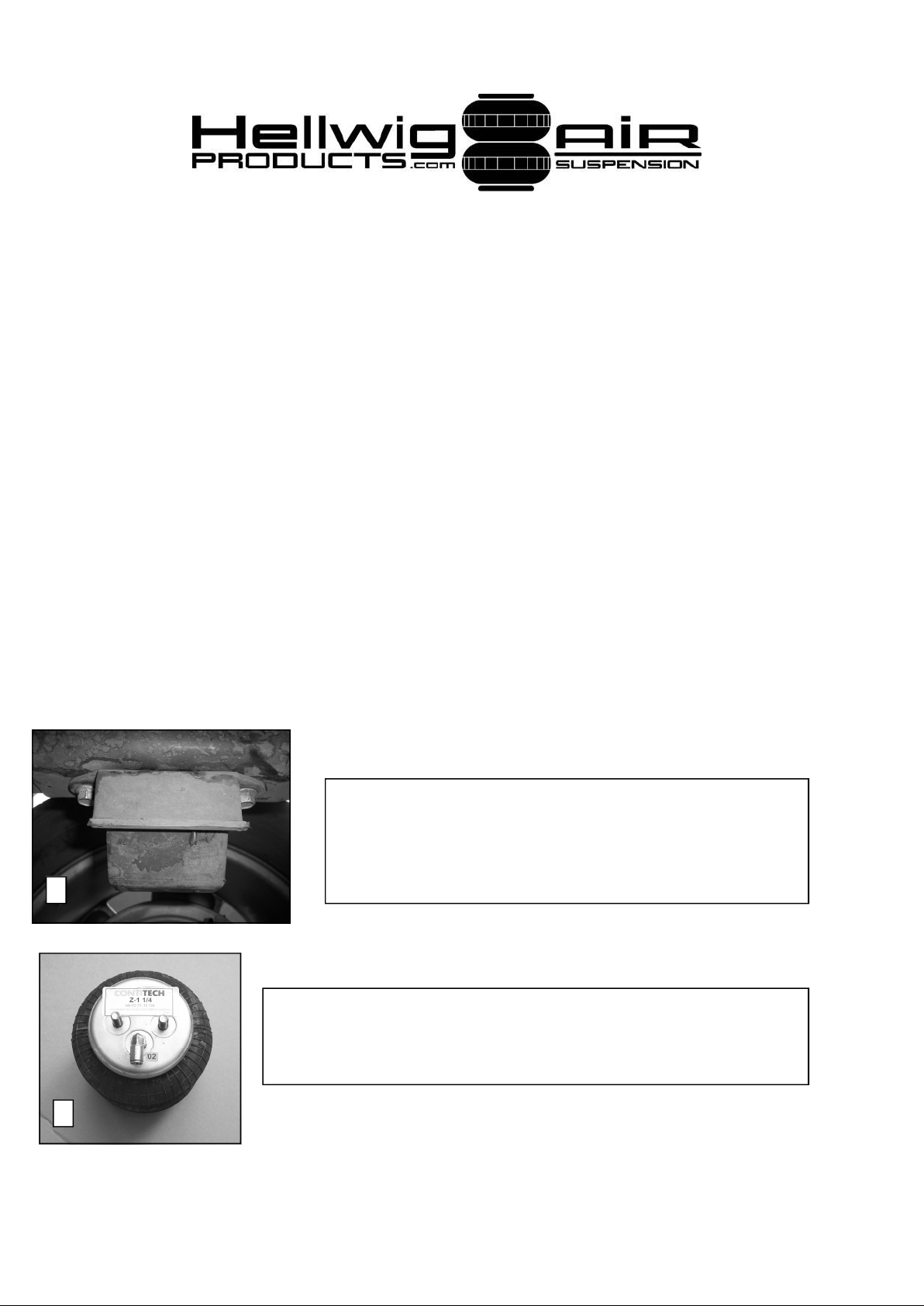
1. Park vehicle securely and set parking brake and
chock wheels. Remove factory bump stops from vehicle by removing nuts from studs using a 15mm
wrench or socket
1
2. Install elbow fitting in port of air spring. Torque fitting to
approximately 20 ft-lb. Make sure that fitting is oriented as
shown in photo.
2
6211 ( R-6211) 11/30/06
Page 3
559-734-7451 800-367-5480 FAX 559-734-7460
3
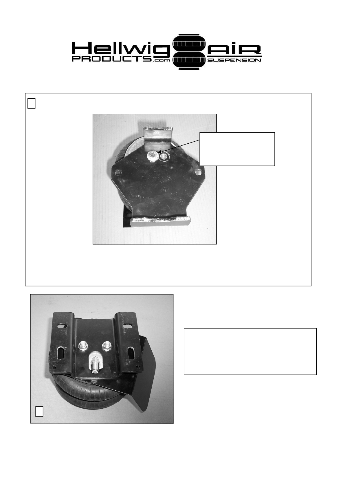
Attach air spring to plate using the forward hole when
bracket is placed on axle.
(Passenger side shown)
3. Lay out base plate as shown in photo. Attach air spring to base plate using 3/8” x
1” bolt as shown in photo. Torque to 20-25 ft-lb.
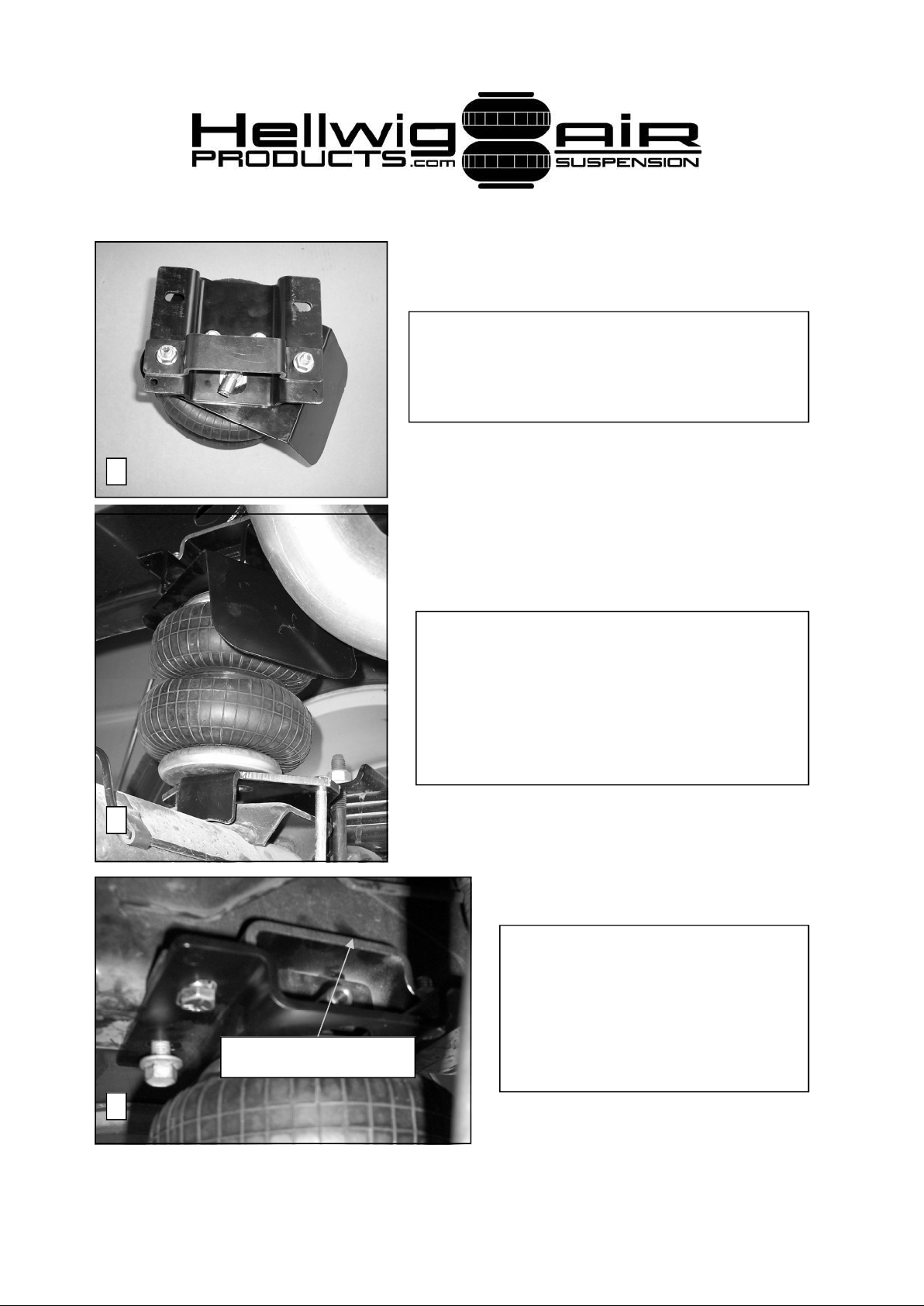
4. Install heat shield and frame bracket
as shown. (Passenger side shown.
Drivers side heat shield not required)
Torque nuts to 20 ft-lb.
4
6211 ( R-6211) 11/30/06
Page 4
559-734-7451 800-367-5480 FAX 559-734-7460
5. Attach reinforcement strap to frame
bracket as shown. Leave loose for adjustment later.
5
6. Insert assembly between frame rail and
axle and attach frame bracket using supplied M10-1.5 x 30 flange bolts to existing
threaded hole in frame. Align bracket and
torque bolts to 20-25 ft-lb.
6
7. Slide reinforcement strap
firmly against frame rail and
tighten fasteners to 25 ft-lb.
Make sure reinforcement strap
Reinforcement strap
fits flush with rail after tightening
bolts.
7
7
6211 ( R-6211) 11/30/06
Page 5
559-734-7451 800-367-5480 FAX 559-734-7460
Driver’s Side
Passenger Side
8
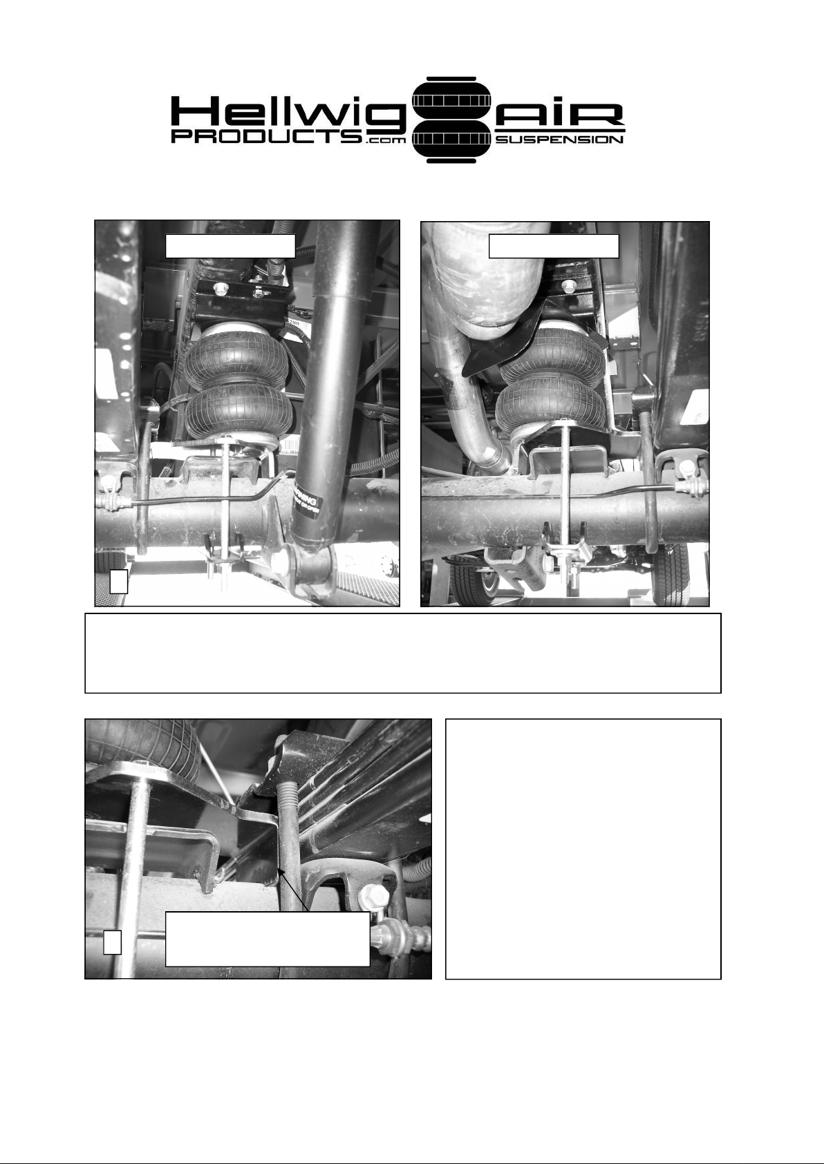
8. Insert cap screws into holes in axle bracket. It may be necessary to reposition
brake line for clearance. Attach saddle using thick washers and locknuts. Slide
axle bracket between legs of u-bolts and tighten bolts to 25 ft-lb.
9. Check your installation to ensure that all fasteners are tight and
that the assembly and all fasteners
clear brake and fuel lines, emergency brake cables, fuel tanks,
wiring harnesses, etc. Make sure
that heat shield is positioned for
maximum protection of air spring.
Make sure that axle bracket is in-
Axle bracket installed
9
6211 ( R-6211) 11/30/06
between legs of u-bolt
stalled between legs of u-bolts as
shown in photo.
Page 6

559-734-7451 800-367-5480 FAX 559-734-7460
10. Complete passenger and driver’s side installation of air spring assembly.
11.Select a location for the air inflation valves. The location can be on the
bumper or body of the vehicle where an air chuck can be used to inflate the air
springs. Select a location where the valve will not be damaged or interfere
with the operation of other components.
12.Cut air brake lines to length and connect air lines to fittings by pushing the air
line into the air fittings as far as possible. WHEN CUTTINGAIR BRAKE
TUBING, A SQUARE CUT IS REQUIRED AND THE HOSE END
MUST NOT BE DEFORMED OR LEAKAGE MAY RESULT. IF DEFORMATION OF THE HOSE END OCCURS, THE HOSE END MUST
BE REWORKED SO THAT IT IS ROUND. Engagement of the sealing
O-ring will be felt when the air line has been inserted properly into the fitting.
Fittings may be disconnected if required by pushing down on the outer ring
while pulling firmly on the air line. Route air lines away from exhaust pipes
or any other sources of heat and ensure that the air lines are protected from
sharp edges. Alength of heat shielding is provided to protect the air line as it
exits the passenger side air spring.
13.Inflate air springs to 40 psi and check for leaks. A soapy water solution can be
used to find slow leaks.
14.When satisfied with integrity of the system, adjust air pressure to desired level.
The air springs can be inflated to any level between 10 and 100 psi. DO NOT
run the air springs empty or warranty will be void. MINIMUM air spring pressure is 5 psi. Failure to keep air in the air springs will void the warranty. For
best RIDE use only enough air pressure as required to level the vehicle. If a
firmer ride is desired, more pressure can be used.
15.Check air pressure in the system regularly to ensure system performance and
maintenance of warranty. Just like tires, the air pressure in the system will
vary due to temperature changes. For your air spring system to function properly it must be checked on a regular basis.
ATTENTION INSTALLER: BE SURE THAT THE CUSTOMER
RECEIVES THIS INSTRUCTION SHEET, ALL IMORTANT NOTE
CARDS AND THE WARRANTY FORM.
6211 ( R-6211) 11/30/06
 Loading...