

Page 1
559-734-7451 800-367-5480 FAX 559-734-7460
INSTALLATION INSTRUCTIONS
Rear Stabilizer Bar for 4” Aftermarket Exhaust
2001-2006 GM 2500HD-3500HD 2WD-4WD
Duramax Diesel Only
Thank you for purchasing a quality Hellwig Product.
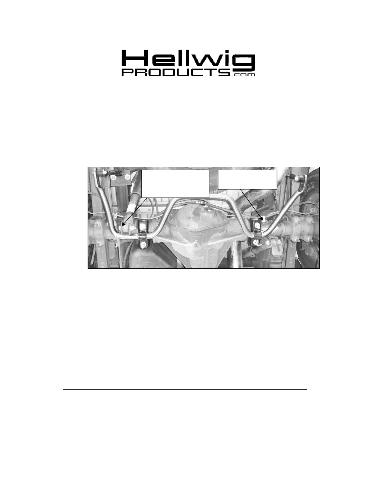
Remove Driver’s side
shock bolt and re-install
with bolt head outboard
SAFETY
AND CHOCK THE WHEELS.
NOTE:
VEHICLE MUST BE ON THE SUSPENSION AS IF DRIVING DOWN THE ROAD. DO NOT RAISE
THE VEHICLE BY THE FRAME.
NOTE:
THE ARMS OF THE BAR TOWARD THE REAR OF THE VEHICLE.
: BEFORE BEGINNING INSTALLATION BE SURE TO SET THE PARKING BRAKE
TO EASE INSTALLATION AND PROPERLY ADJUST THE BAR, THE WEIGHT OF THE
THIS UNIT IS DESIGNED TO MOUNT TO THE BOTTOM OF THE AXLE TUBES WITH
Relocate brake cable/
line bracket.
1. Lubricate the D shaped bushings and place them on the straight areas of the bar on each side of
the center hump.
2. Hold bar up to the axle and locate the position on the axle tubes to mount the u-bolts. Be sure to
put the U-Bolts Under Any Brake Lines, Wires or Hoses on the Axle to Avoid Any Possible
Damage. The threads of the U-Bolts will point down.
3.
The saddle brackets have different radiuses to match the taper of the axle.
Install
saddles on axle so that they sit squarely on the axle. Place the U-Plates over the D shaped bushings on the bar and attach the bar to the U-Bolts and saddle brackets with the flat washers and
nuts provided. LEAVE LOOSE AT THIS TIME to allow for adjustment later.
4. Remove brake cable/line bracket from axle and use z-bracket and 5/16 bolt and nut to relocate as
shown in photos. Remove the driver side lower shock bolt, turn it around and reinstall from
the outboard side of the lower shock bracket.
7721 (R-7721) 04/24/2012
Page 2
559-734-7451 800-367-5480 FAX 559-734-7460
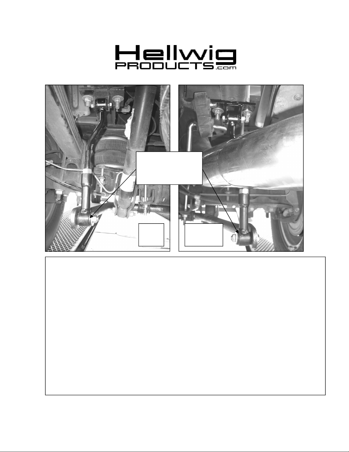
Remove Driver’s side
shock bolt and re-install
Attach end link to
rear most hole for
with bolt head outboard
initial installation
Driver
Side
5. Locate existing spare tire crossmember on vehicle frame. Place square U-bolt over the frame rail in front
of the crossmember with the legs of the U-bolt pointing downward.
6. Insert the legs of the U-bolts into the slotted holes of the frame brackets. Using 1/2” locknuts and washers, install the frame bracket with the clevis on the rear side of the bracket as shown in photos. LEAVE
LOOSE for adjustment later.
7. Assemble end links by inserting the hourglass bushing first and then the sleeve into the loops of the end
links. Lubricate the bushing and sleeve before assembly. Attach 9/16 nut to threaded half of end link
before assembling end link halves.
8. Attach end links to clevis on frame brackets using 7/16 X 2-1/4 bolts and locknuts. LEAVE LOOSE for
adjustment later.
9. Adjust end links so that the arms of the sway bar are parallel with the ground. When satisfied with fit,
attach end links to the rearmost hole of sway bar with 7/16 x 2-3/4 bolts, washers, and locknuts. A
washer can be placed between the sway bar and end link bushing to aid alignment of the end links.
10. Tighten frame bracket U-bolts to 45-50 ft-lb. Make sure outboard leg of u-bolt is pushed against frame
rail before final torque to 45-50 ft-lb.
11. Tighten end link bolts on sway bar and frame brackets to 40 ft-lb. Tighten 9/16” nut on end links to lock
threads in place.
Passenger
Side
7721 (R-7721) 04/24/2012
Page 3
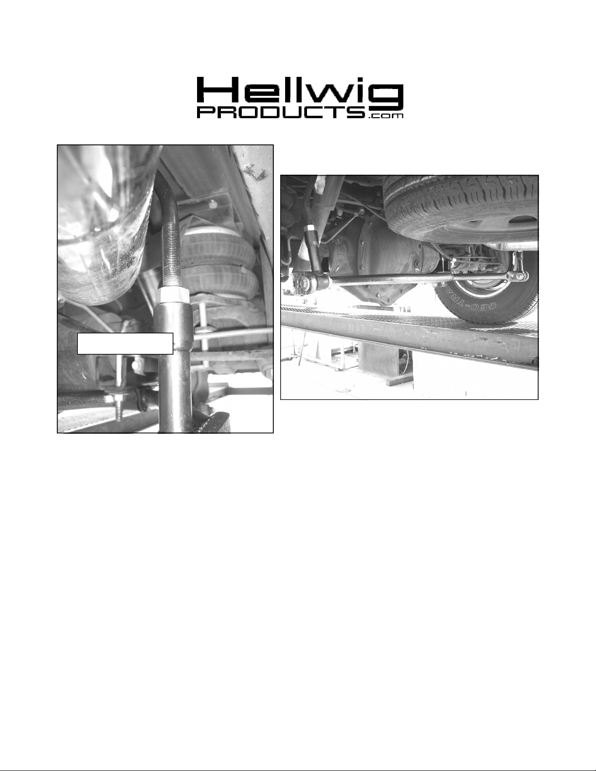
Driver’s Side
Passenger Side
559-734-7451 800-367-5480 FAX 559-734-7460
12. Center sway bar on axle and tighten axle U-bolts to 60 ft-lb. Double nut axle u-bolts after torquing to spec.
13. Bounce the vehicle checking for clearance on all under carriage components: fuel tank, shocks, exhaust,
differential, brake and fuel lines, etc. Test drive the vehicle and recheck all clearances and the installation
alignment. Adjust as needed. Re-check your installation after one week of driving and periodically on a regular
basis.
14. The sway bar has three end link mounting holes. The end link MUST be mounted on the outer hole for
initial use. For a firmer setting, use the inner holes. You must use the outer mounting hole until you are
accustomed to the vehicles new handling characteristics. After driving vehicle, a firmer setting may be
selected if desired. It is recommended that the outer hole be used for street driving.
ATTENTION INSTALLER: PLEASE MAKE SURE CUSTOMER RECEIVES THIS INSTRUCTION
SHEET,ALL IMPORTANT NOTE CARDS, WARNING CARDS AND THE
WARRANTY FORM
7721 (R-7721) 04/24/2012
 Loading...