

Page 1
559-734-7451 800-367-5480 FAX 559-734-7460
INSTALLA TION INSTRUCTIONS
Rear Stabilizer Bar
4X2 & 4X4 1500-2500 SIERRA AND SILVERADO ALSO INCLUDES 1500
HD TRUCKS
Thank you for purchasing a quality Hellwig Product.
1
2 3 4
7634 ( R-378) 01/09/04
5
Page 2

559-734-7451 800-367-5480 FAX 559-734-7460
TORQUE TABLE
BOLT SIZE: 3/8” = 20-30 ft. lbs. – 7/16” = 35-45 ft. lbs. – ½” = 50-70 ft. lbs. – 9/16” = 70-90 ft. lbs. –5/8”=120 ft lbs.
NOTE: THIS UNIT IS DESIGNED TO MOUNT WITH THE ARMS OF THE SWAY BAR TOWARDS THE REAR OF THE VECHILE.
SAFETY: BEFORE STARTING YOUR INSTALLATION BE SURE TO SET THE EMERGENCY BRAKE AND WHEELS ARE CHOKED.
NOTE: TO EASE INSTALLATION AND PROPERLY ADJUST THE BAR, THE WEIGHT OF THE VEHICLE MUST BE ON THE SUS
PENSION AS IF DRIVING DOWN THE ROAD. DO NOT RAISE THE VEHICLE BY THE FRAME.
NOTE: THIS KIT INCLUDES LOCK NUTS WHICH REQUIRE TIGHTENING WITH A WRENCH AFTER BEING STARTED BY HAND.
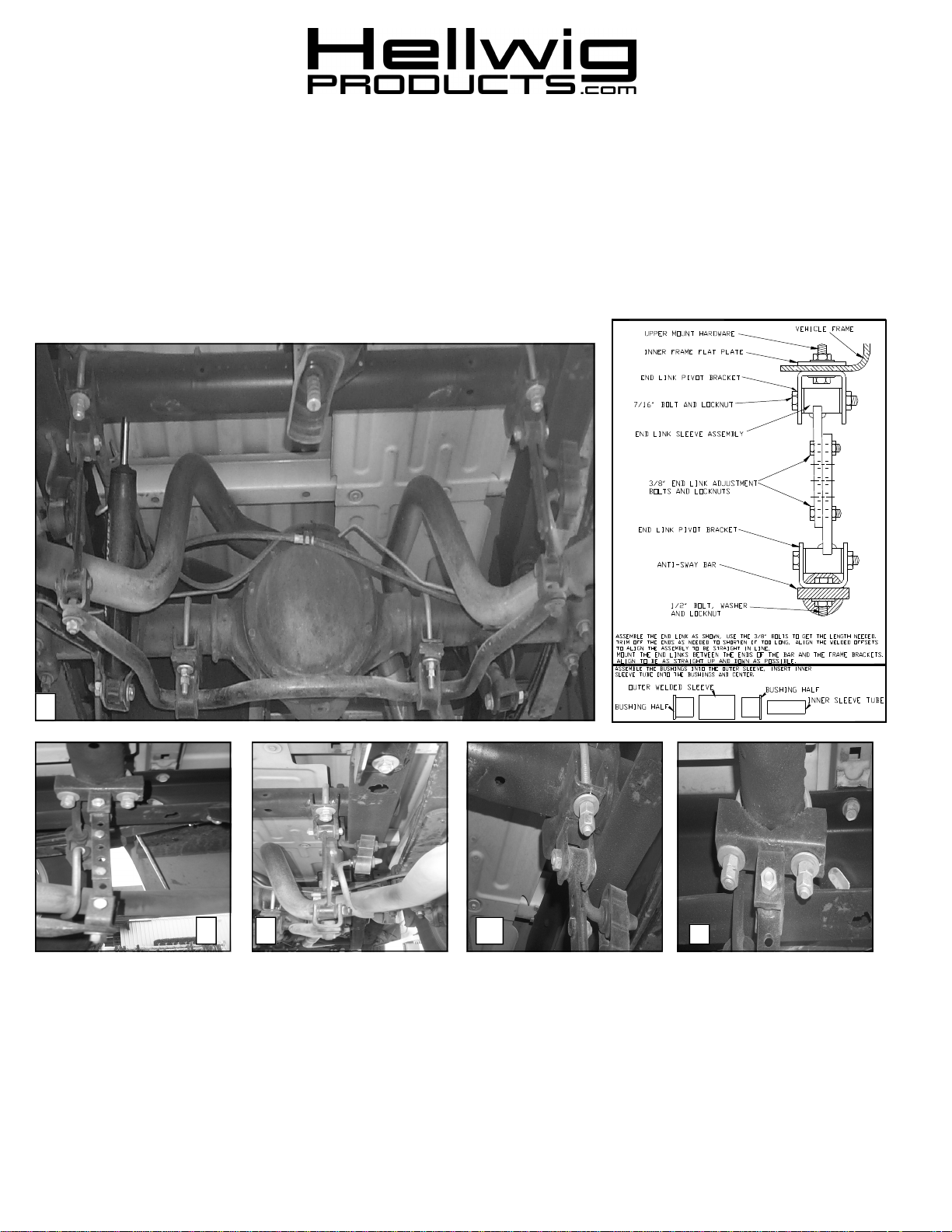
1. Install the D-shaped poly-bushings onto the flat areas of the bar on each side of the hump area. Hump of
the bar should tilt slightly downward. SEE PHOTO #1
2. Place U-bolts on axle inside of the shock mounts. Make sure U-bolts are under the any brake lines,
wires, or hoses on the axle to avoid pinching or crushing when tightening. The threads should be
pointing downward.
3. Place the U-plates onto the bushings mounted on the bar earlier. Place the saddle brackets onto the U-bolts
on the axle tubes and attach the U-plates using the flat washers and nuts provided. Leave loose at this
time to allow for adjustment later.
4. Rotate the bar on the axle tubes and adjust side to side so the bar is as centered as possible and has clearance around the differential housing.
5. assemble the pivot bushings and inner sleeves into the ends of the end-links. Attach the U-shaped pivot
clevis bracket to the end of the bar. SEE DIAGRAM.
6. Place the second set of U-bolts around the tubular cross member above the spare tire just inside the frame
rails with the legs pointing down. Place the saddle bra ckets with the welded U-shaped clevis on to the
cross member mounted U-bolts. Make sure U-bolts are under any lines or wires to avoid pinching or
crushing when tightening. Leave loose at this time to allow for adjustment. SEE PHOTO # 4 & 5.
7. Attach the end-links into the upper clevis brackets with the 7/16” hardware provided and let hang. Leave
all mounting hardware loose at this point to allow for adjustment later. SEE PHOTO # 2 .
8. Attach the lower end-links to the U-shaped clevis brackets mounted to the ends of the bar earlier. Raise
the bar up so the arms are as close to level as possible and connect the two end-links halves together.
Be sure to use two bolts to connect each end link. Use the variety of holes in the end-links to adjust the
length for your particular vehicle. You can trim of the ends if needed to allow the end-links to become
shorter. Always use two bolts to connect the end-link halves together. SEE PHOTO # 2 & 3.
9. Rotate the U-bolts on the axle and tubular cross member to align the bar so it is as level with the frame as
possible and the end-links are straight up and down as possible. Be sure that the axle and cross member
U-bolts are under any brake lines, wires or hoses to avoid pinching or crushing when tightening.
10. With the bar properly aligned, and all vehicle components have proper amount of clearance, and nothing is
going to be pinched or crushed when everything is tight. Torque all mounting hardware to the specified
rates and double nut the axle and cross member U-bolts.
11. Bounce the vehicle checking for clearance on all under carriage components. Exhaust, shocks, differential,
etc. Test drive the vehicle and recheck all clearances and the installation alignment. Adjust as needed. Re check your installation after one week of driving and periodically on a regular basis.
ATTENTION INSTALLER: BE SURE CUSTOMER RECIEVES THIS INSTRUCTION SHEET, WARNING CARDS
AND THE WARRANTY FORM.
7634 ( R-378) 01/09/04
Page 3

PARTS LIST
RSB KIT # 7634
“99-01” 2X4 & 4X4 SILVERADO & SIERRA 1500-2500
“02” 2X4 1500HD
PART # QTY DESCRIPTION
20217634 1 SWAY BAR 1-1/8” O.D.
20800774 4 WELDED END LINK
20800430 2 U-PLATE
20801980 2 SADDLE BRACKET WITH WELDED CLEVIS
111000486 2 (1-1/8”) POLY BUSHING
118000672 4 (7/16” X 3-1/8” X 5-5/8”) ROUND U-BOLT
20800871 2 SADDLE BRACKET
20800789 2 CLEVIS BRACKET
125000853 1 SLEEVE BUSHING BAG # BG-853
111000853 8 END LINK SLEEVE BUSHING
20800722 4 END LINK STEEL SLEEVE
125000098 1 SMALL PARTS BAG # BG-98
105521044 2 (1/2”) HEX NUT
107521044 2 (1/2”) LOCK NUT
102520043 2 (1/2”) FLAT WASHER
101500307 2 (1/2” X 1-1/4”) CAP SCREW
101500185 4 (7/16” X 2-1/4”) CAP SCREW
101500008 4 (3/8” X 1”) CAP SCREW
107302003 4 (3/8”) STOVER LOCK NUT
102420041 8 (7/16”) FLAT WASHER
107401042 16 (7/16”) LOCK NUT
105421042 4 (7/16”) HEX NUT
135007534 1 INSTRUCTION SHEET R-7634 (R-378)
 Loading...