

Page 1
INSTALLATION INSTRUCTIONS
Rear Stabilizer Bar 7269
2001-2006 GM 2500HD-3500HD 2WD-4WD
Thank you for purchasing a quality Hellwig Product.
PLEASE READ THIS INSTRUCTION SHEET COMPLETELY BEFORE STARTING YOUR INSTALLATION
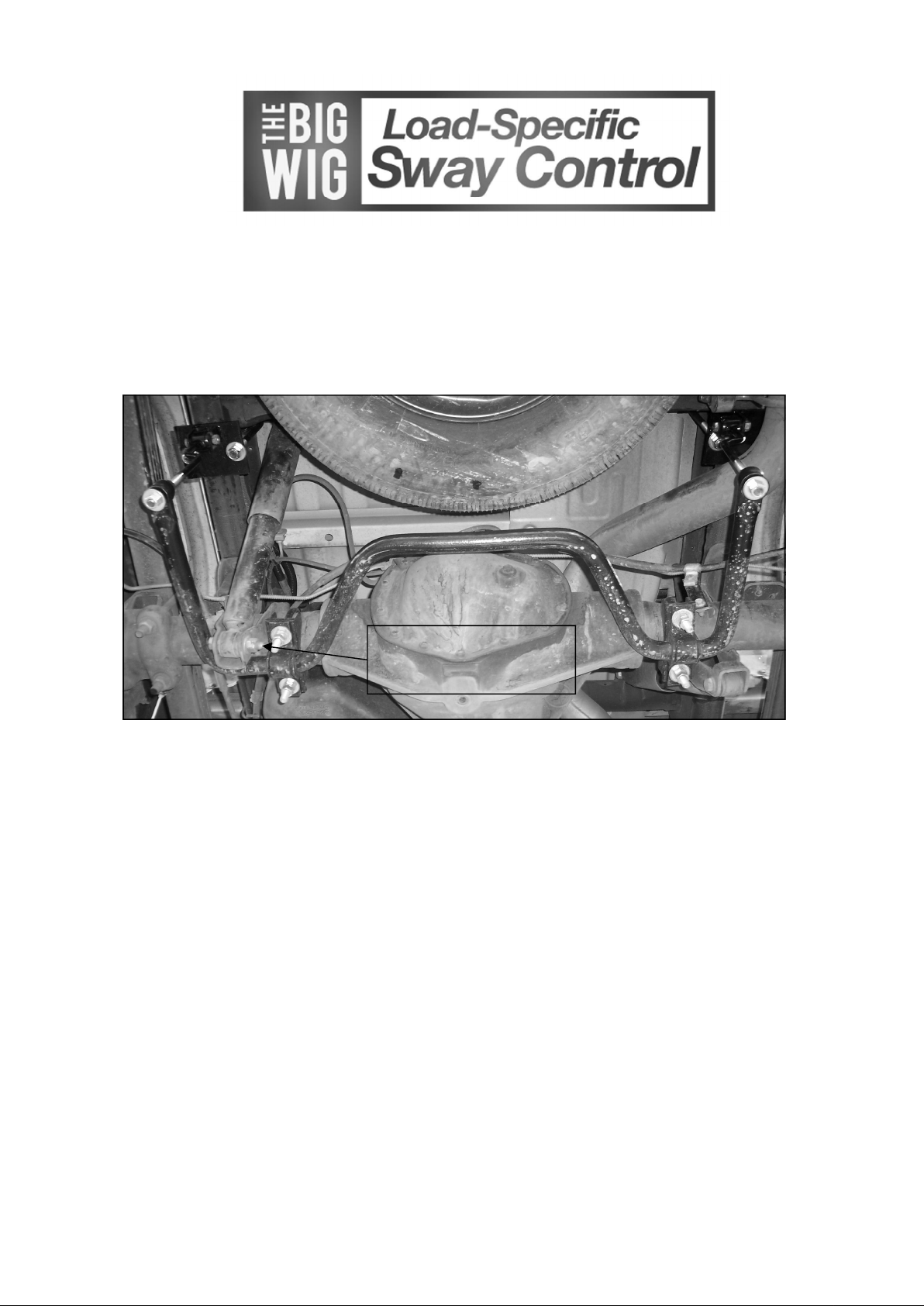
Remove shock bolt and reinstall with bolt head facing outboard for sway bar clearance.
TORQUE TABLE
Bolt Size 3/8”— 25 ft lbs * Bolt Size 7/16”— 35 ft lbs* Bolt Size 1/2”—60 ft lbs *
SAFETY: BEFORE BEGINNING INSTALLATION BE SURE TO SET THE PARKING BRAKE
AND CHOCK THE WHEELS.
NOTE: TO EASE INSTALLATION AND PROPERLY ADJUST THE BAR, THE WEIGHTOF THE
VEHICLE MUST BE ON THE SUSPENSION AS IF DRIVING DOWN THE ROAD. DO NOT RAISE
THE VEHICLE BY THE FRAME.
NOTE: THIS UNIT IS DESIGNED TO MOUNT TO THE BOTTOM OF THE AXLE TUBES WITH
THE ARMS OF THE BAR TOWARD THE REAR OF THE VEHICLE.
1. Place the D shaped bushings onto the straight areas of the bar on each side of the center hump.
2. Hold bar up to the axle and locate the position on the axle tubes to mount the u-bolts. Be sure to put the
U-Bolts Under Any Brake Lines, Wires or Hoses on the Axle to Avoid Any Possible Damage. The
threads of the U-Bolts will point down.
3. Remove brake cable/line bracket from axle and use single flat plate to relocate higher.
4. Place saddle brackets onto the U-Bolts on the axle tubes. The saddle brackets have different radius to ac-
commodate the taper in the axle tube. If they do not sit square, reverse their orientation. Place the U-Plates
over the D shaped bushings on the bar and attach the bar to the U-Bolts and saddle brackets with the flat washers and nuts provided. LEAVE LOOSE AT THIS TIME to allow for adjustment later. For additional bar
clearance remove the driver side lower shock bolt, turn it around and reinstall from the opposite side of
the lower shock bracket.
7269 (R-7269) 11/19/2010
Page 2
559-734-7451 800-367-5480 FAX 559-734-7460
Driver’s Side
Passenger Side
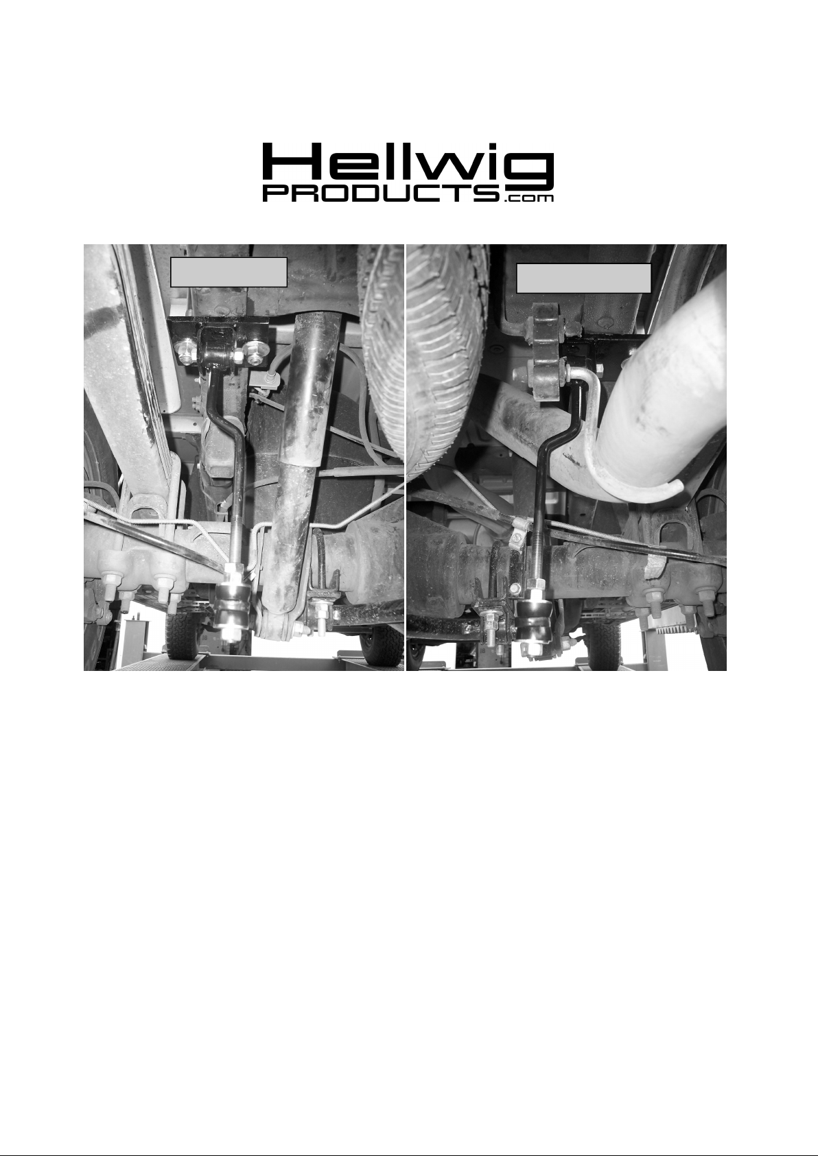
5. Locate existing spare tire crossmember on vehicle frame. Place square U-bolt over the frame rail in front of the crossmember with legs of the U-bolt pointing downward.
6. Insert the legs of the U-bolt into slotted holes of the frame brackets. Using 1/2” locknuts and washers, install the frame
bracket with the centered clevis on the driver side of vehicle as shown in photos. Install the frame bracket with the offset
clevis on passenger side of vehicle as shown in photos. LEAVE LOOSE for adjustment later. ( FINAL TIGHTENING
ON FRAME U-BOLTS : Push outer u-bolt leg against frame rail. Snug nuts to frame bracket then torque outboard nut first to 20 ft-lb and then inboard nut to 20 ft-lb. Final torque outboard nut first to 35 ft-lb and then inboard nut to 35 ft-lb. )
7. Insert hourglass bushing and then sleeve into end link assembly. Lubricate the bushing and sleeve to ease assembly.
8. Attach end links to clevis on frame bracket as shown using the 7/16 x 2 1/4” bolts. LEAVE LOOSE for adjustmentlater.
9. Raise bar ends upward to be level with the frame and attach end links to sway bar ends as shown in photos using the hardware provided. Use the 1/2” lock nut on the end of the end link assembly.
10. Align bar from side to side through the D-bushings to be as centered as possible. Rotate bar front to rear by rotating the UBolts on the axle. Adjust frame brackets so that the end-links are straight up and down as possible. Be sure the bar does
not contact the differential, shocks, or leaf springs.
11. Torque all of the mounting hardware to the specified rates. Double-nut axle u-bolts with supplied nuts and tighten to lock
nuts together. Bounce vehicle, checking for clearance on all undercarriage components, ie: exhaust, shocks, fuel lines,
brake lines, etc.
12. Recheck installation periodically on a regular basis.
ATTENTION INSTALLER: PLEASE MAKE SURE CUSTOMER RECEIVES THIS INSTRUCTION
SHEET,ALL IMPORTANT NOTE CARDS, WARNING CARDS AND THE
7269 (R-7269) 11/19/2010
 Loading...