

Page 1
559-734-7451 800-367-5480 FAX 559-734-7460
INSTALLA TION INSTRUCTIONS
REAR STABILIZER BAR
70-81 CAMARO & FIREBIRD
Thank you for purchasing a quality Hellwig Product.
PLEASE READ THIS INSTRUCTION SHEET COMPLETELY BEFORE STARTING YOUR INSTALLATION
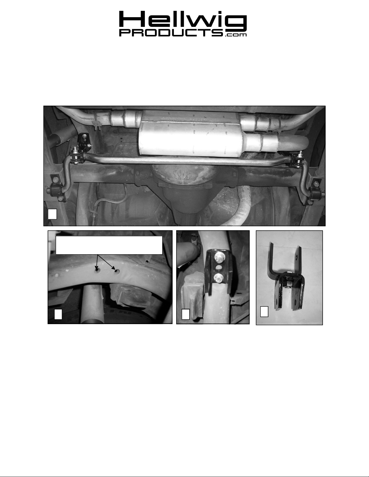
1
Locate holes in frame to mount frame
bracket using supplied 3/8-16 X 1” bolts.
2 3
TORQUE TABLE
BOLT SIZE: 3/8” = 20-30 ft. lbs. – 7/16” = 35-45 ft. lbs. – ½” = 50-70 ft. lbs. – 9/16” = 70-90 ft. lbs.-5/8”=120 ft. lbs
4
SAFETY: BEFORE STARTING YOUR INSTALLATION, BE SURE TO SET PARKING BRAKE AND CHOCK
TIRES.
NOTE: THIS UNIT IS DESIGNED TO REPLACE THE FACTORY INSTALLED REAR ANTI-SWAY BAR. OR AS
AN ADDITION IF THE VEHICLE WAS NOT EQUIPPED WITH A FACTORY REAR SWAY BAR.
NOTE: THIS KIT INCLUDES LOCKNUTS WHICH REQUIRE TIGHTENING WITH A WRENCH AFETR BE
ING STARTED BY HAND.
5802 ( R-5802 ) 02/15/07
Page 2
559-734-7451 800-367-5480 FAX 559-734-7460
559-734-7451 800-367-5480 FAX 559-734-7460
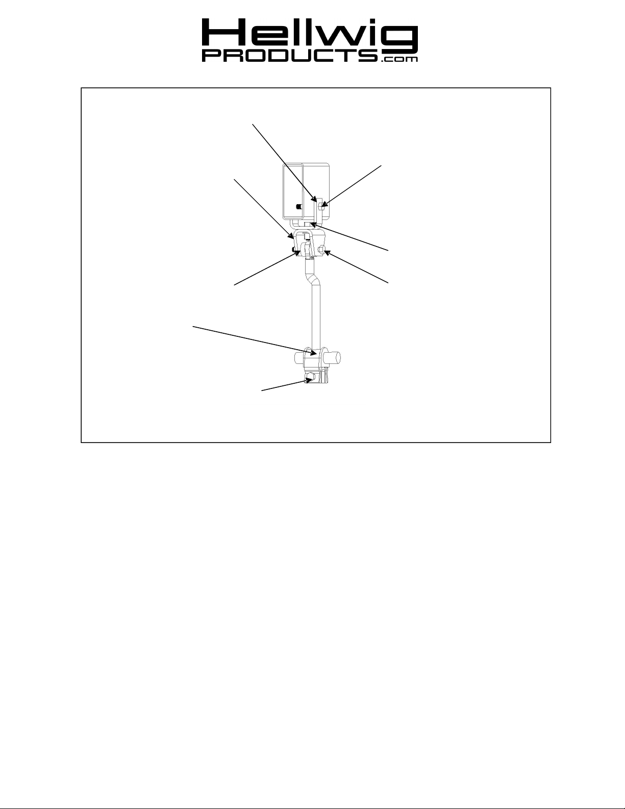
This bracket not required if predrilled holes exist in frame.
Mount this bracket to frame
with 3/8 x 1” bolts if pre-drilled
holes exist in frame. If holes
not present, mount to ubracket with 1/2” bolt as
shown.
3/8 x 3-1/4” bolt and locknut
through subframe requires .468 dia clearance hole.
Fully mount sway bar to vehicle to determine location of
hole. Torque to 25 ft-lb
1/2 x 1” bolt and locknut.
Torque to 50 ft-lb
Round Bushings
D-Bushing
3/8 x 2 1/2 bolt, lockwasher,
and nut. Tighten until hanger
contacts bushing support.
3/8 x 2 1/2 bolt and locknut.
Torque to 25 ft-lb or until
bushings bulge slightly.
1. If equipped, remove factory sway bar.
2. Locate the pre-drilled holes in the subframe as shown in photo (2). Attach frame bracket
to subframe using factory hardware if equippe d with factory sway bar. If pre-drilled
holes are not threaded, use a 3/8-16 tap to thread holes and attach bracket using 3/8 X 1”
bolts, washers and lockwashers. See photo (3) for attachment of frame bracket. Torque
bolts to 20 ft-lb.
3. If your vehicle does not have these holes see diagram above and photo (4) for assembly
of frame bracket and end link. FULLY MOUNT SWAY BAR BEFORE DRILLING
HOLES IN SUBFRAME FOR CORRECT ALIGNMENT OF SWAY BAR AND END
LINKS. Make sure all fuel and brake lines, brake hoses, and brake cables are protected
before drilling any holes in subframe.
4. Place a round bushing on each side of end link hole and slide assembly into frame
bracket. Attach end link to frame bracket using 3/8 x 2 1/2” bolt and locknut. See photo
(5) and diagram. Leave loose at this time at this time to allow for adjustment.
5. Lubricate the D-bushings and locate on sway bar as shown in photo (1).
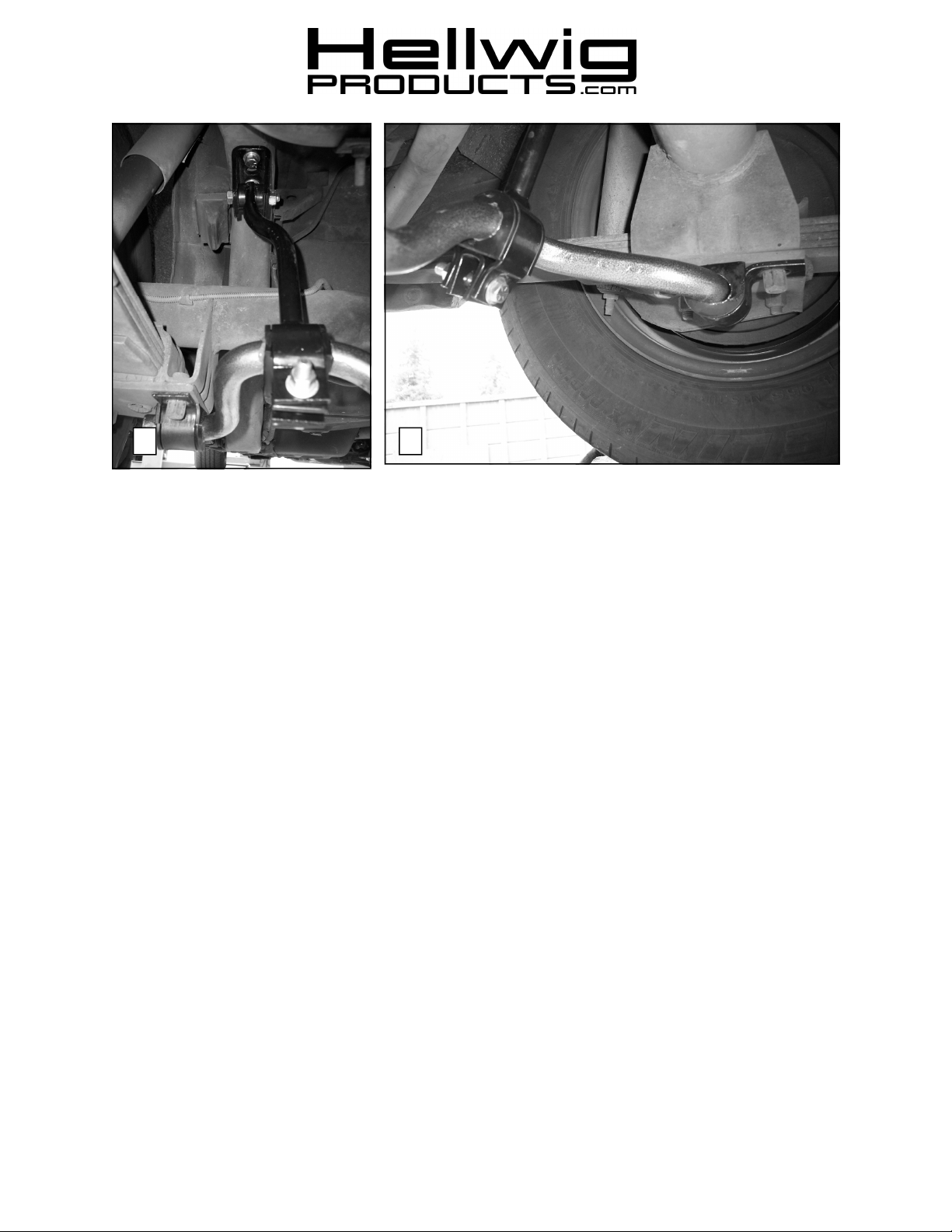
6. Position D-bushings in hanger of end link as shown in diagram and photo (6). Insert ushaped bushing support into hanger and attach with 3/8 x 2 1/2” bolt, washer and nut.
5802 ( R-5802 ) 02/15/07
Page 3
559-734-7451 800-367-5480 FAX 559-734-7460
5 6
7. Lubricate d-bushings and place on end of sway bar as shown in photo (6). Attach dbushings to spring plate with supplied u-plate and factory fasteners.
8. Tighten bolts in spring plate to factory specification.
9. If holes were drilled in subframe to mount hanger, tighten through-bolt to 25 ft-lb.
10. Tighten end link hanger bolts to 25 ft-lb or until bushings bulge slightly.
11. Bounce vehicle a couple of times and check installation for clearance to fuel and brake
lines and other components. After one week of driving recheck your installation and
fastener torque. Recheck on a regular basis thereafter.
ATTENTION INSTALLER: BE SURE THAT THE CUSTOMER RECEIVES THIS INSTRUC
TION SHEET, ALL IMORTANT NOTE CARDS AND THE
WARRANTY FORM
5802 ( R-5802 ) 02/15/07
 Loading...