

Page 1
Customer Service: 1-800-288-6794
(for U.S. and Canada)
Customer Service E-mail:
ccitech@commandcom.net
3
Page 2

Before you begin
This guide is designed to introduce you to the various
installation and operational procedures for using the
ComSwitch 5500 (CS 5500).
Please read through this guide and select the installation
procedures appropriate for your specific application before
attempting to connect or operate the CS 5500.
Important Notes
According to standard industry practice, surge protection is
recommended for use with all electronic devices. A surge
suppressor and/or line conditioning should be used on the input
power supply, as well as the connected telephone line.
Call Waiting: Fax machine and modem transmissions could be
disrupted by the call waiting beep tone.
NOTE: We recommend that you disconnect service for Call Forwarding.
Introduction to the CS 5500
Thank you for purchasing the CS 5500. Data communications is
becoming increasingly popular, and the CS 5500 allows you to
take advantage of this technology.
The CS 5500 is a state-of-the-art Telephone Line Sharing
device which eliminates the extra dedicated telephone lines
used to operate a fax, modem, or other telephone device.
Call Forwarding: If Call Forwarding is activated, the
CS 5500 cannot process calls on that line. We recommend that
you disconnect service for Call Forwarding.
Phone Company Voice Mail: This service is compatible
with the CS 5500 if used in conjunction with the phone
company's Distinctive Ring service (service activation
required).
Listed below are examples of various telephone activated
devices that can be connected to the CS 5500.
z
Fax / modem
z
Call diverter
The CS 5500 quickly directs incoming telephone calls to one of
four appropriate destinations, typically a computer modem or
fax/modem and facsimile machine, as well as a telephone and
answering machine, or any other telephone device that responds
to a standard phone company ring signal.
Please read through the rest of this guide to learn how to
properly install and operate the CS 5500.
z
Computer modem
z
Fluid storage system
z
Facsimile
z
Laser fax cartridge
z
Answering Machine
z
Energy management system
z
Telephone
z
Time and attendance
z
Bulletin Board System (BBS)
z
Money order dispensing system
z
Credit Card Authorization Terminal
z
Remote diagnostic system
z
Page 3
Unpacking the CS 5500
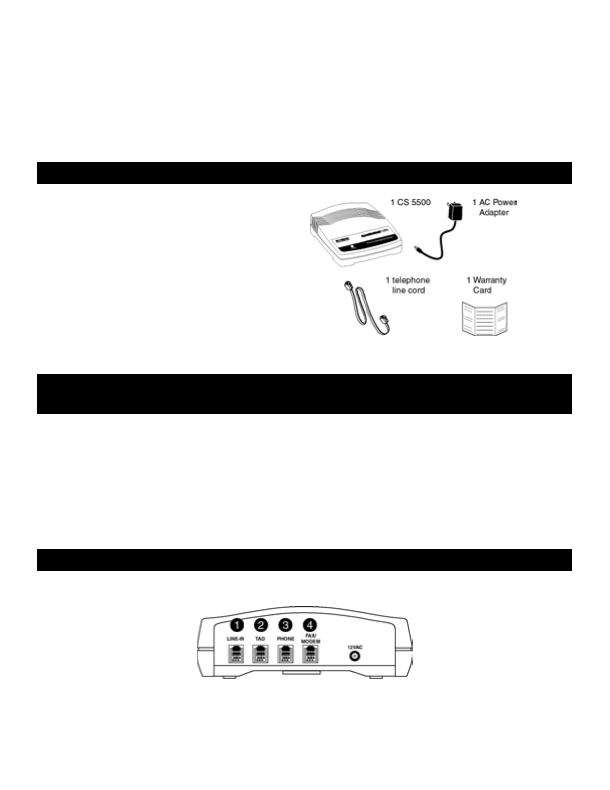
When you open the CS 5500 box for the first time, inspect the
contents. In the box you should find the items to the right.
If any of these items are missing or damaged, contact the dealer
where you purchased the unit, or call Customer Service at the
number listed in "Two year limited warranty/Service
Information."
Security alarm and monitoring system
z
Flow monitoring system
z
Point-of-sale terminal
1 CS 5500 Operator’s Guide
Installing the CS 5500
The CS 5500 is a single line telephone device that can be
installed on any type of modular or non-modular system that
consists of one or more lines, with one or more phones. A
modular system consists of phone cables that can be connected
and disconnected from a telephone device.
A non-modular system consists of cables that are hard-wired to
the telephone device and cannot be disconnected from the
equipment.
A telephone installer may be required to install the CS 5500 on
a non-modular system.
NOTE: Many offices have a KSU or PBX phone system. The
CS 5500 works with either of these systems. Simply follow the
appropriate installation instructions provided in "Installation on
a telephone system."
Ports on the CS 5500
The rear panel of the CS 5500 includes four (4) modular ports and a power input port, as shown:
Connect a single telephone line from a standard telephone
(wall) jack to this port.
Connect a single line Telephone Answering Device
Connect your fax machine to the FAX/MODEM port. A
computer modem or fax/modem can also connect to this
port in lieu of a fax machine.
Page 4
(TAD) or integrated phone/answering machine to this
port.
Depending on the installation, a single line phone, an
integrated phone/answering machine, multiple phones, or
a telephone system (KSU or PBX) can be connected to
this port
The CS 5500 will transfer all voice calls to the TAD and
PHONE ports simultaneously.
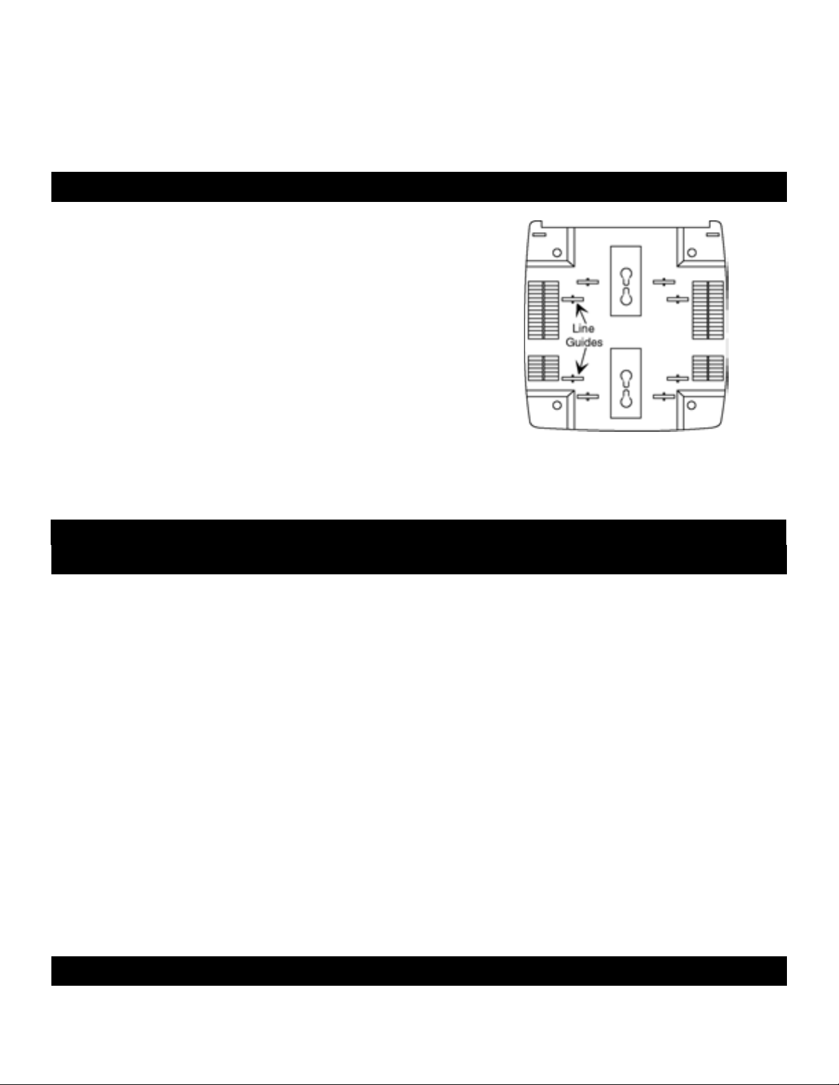
Placing the CS 5500
The CS 5500 can be placed on either a flat surface, or mounted on a wall
with the connected telephone line cords above or below the unit. To
mount on a wall, follow these steps:
1. Mark the positions for 2 mounting screws (not supplied) on the wall.
The positions should be 3 1/4" apart (vertically). Drill the 2 holes,
then thread the screws into the wall. The screws should extend 3/16".
Do not over tighten the screws.
2. Align the keyholes on the back of the CS 5500 with the 2 screws, then
push in and press down to secure it to the wall.
You can place the telephone line cords through the line guides on the
back of the CS 5500 to reduce tangling.
NOTE: If you place the CS 5500 on a flat surface, do not place it in close proximity to any peripheral equipment
(approximately 2 to 3 feet away from all electronic equipment).
CS 5500 Operator’s Guide 2
Connecting the CS 5500
This section explains how to install the CS 5500 in most phone
configurations that appear in a home or office. You can install
the CS 5500 into one of the following phone configurations:
Installation procedures for each of these configurations are provided in the following sections.
To perform the installation procedures in the following
sections, you may need the following equipment:
z
telephone cables to connect the CS 5500 to your
telephone (wall) jack.
z
extension cables--required if the connecting equipment is not
located near the CS 5500.
z
a single telephone line
z
a telephone system
z
additional telephone cables -- typically supplied with equipment
by the manufacturer. You need additional telephone cables for
as many pieces of equipment as you intend to connect to the CS
5500. If the equipment manufacturer does not provide the
required cables, you can purchase them at a consumer
electronics store.
Installation on a single telephone line
The following diagram shows a complete installation for a phone systems, the connections to the CS 5500 remain the same
Page 5
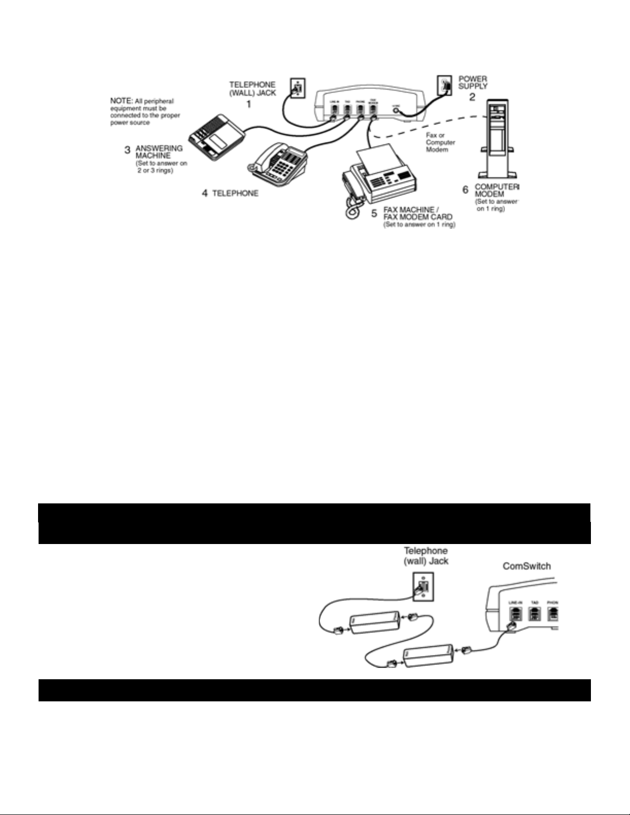
single phone line connection. While the connections to the
telephone (wall) jack may be different for other types of
for all phone configurations.
1. Plug one end of a telephone line cord into the LINE-IN
port on the CS 5500. Plug the other end of the modular
line cord into the telephone (wall) jack.
2. Plug the small end of the AC power cord provided with
the CS 5500 into the power input port labeled "12 VAC"
on the CS 5500. Plug the adapter into a standard AC
outlet.
The green LED flashes rapidly for about 5 seconds when
power is applied and then remains illuminated, indicating
its ON status.
3. To connect an answering machine, plug one end of a
telephone line cord into the TAD port on the CS 5500.
The factory setting for Caller ID operation is OFF.
To turn Caller ID ON, perform the following steps:
1. Take the phone in the PHONE port off-hook
2. Press # * 116 * (three beeps) 402 * (three beeps) *
3. Hang up the phone
NOTE: Caller ID is a service provided by your local telephone company. (Service activation required.)
4. To connect a phone, plug one end of a telephone line cord
into the PHONE port on the CS 5500.
5. To connect a fax machine, plug one end of a telephone
line cord into the FAX/MODEM port on the
CS 5500. Set the fax to answer on 1 ring.
6. To connect a telephone device such as a computer
modem, in lieu of a fax machine, plug one end of a
telephone line cord into the FAX/MODEM port on the
CS 5500. Set the modem to answer on 1 ring.
NOTE: To connect a Caller ID device with the CS 5500,
simply plug the Caller ID into the PHONE port,
then plug your phone into the Caller ID.
To turn Caller ID OFF, perform the following steps:
1. Take the phone in the PHONE port off-hook
2. Press # * 016 * (three beeps) 401 * (three beeps) *
3. Hang up the phone
3 CS 5500 Operator’s Guide
Connecting the CS 5500 to an ADSL Phone Line
Two 8K In-Line Microfilter phone filters are required –
available from most consumer electronics stores.
Connect your filters as shown:
1. Connect the two filters together in series.
2. Plug one end of the connected filters into the
telephone (wall) jack.
3. Plug the other end into the LINE-IN port on the
CS 5500.
Installation on a telephone system
A telephone system is common in a medium or
large office arrangement in which calls are
coming in on 2 or more telephone lines and can
be routed to any number of extensions. The
Page 6

system typically has features like call holding,
music on hold, conference calling, and intercom
paging.
The diagram shows telephone devices
connected to the CS 5500 for a telephone
system; follow the same procedures if you have
a mini-telephone system in your home or small
office.
For the CS 5500 to operate properly, it must be "in front"
of the telephone system. In other words, it must connect
directly to the incoming telephone line.
Connect the other equipment as previously shown.
CAUTION: You should be familiar with telephone wiring to complete this installation. If you have any questions or are not
confident that you can complete this installation procedure, contact the Customer Service Center in the "Warranty" section of this
guide or a professional installer for further instructions.
Do not plug the CS 5500 into a telephone system phone jack. You may damage your phone system.
All equipment on that line (telephone system, fax, computer
modem, and so on) must connect directly to the CS 5500.
Using the CS 5500
In this section, there are special operating notes you should read before operating
the CS 5500. This section follows an overview of the CS 5500 standard operations
and instructions for answering and transferring your incoming calls.
CS 5500 Operator’s Guide 4
Standard operation
The CS 5500 has 2 modes of operation, Automatic mode and Semi-Automatic mode. The factory setting is in the Automatic mode.
Page 7

Automatic mode operation
When a call comes in, the CS 5500 answers the call on the first
ring (second ring if Caller ID is turned ON). During the next
four seconds the CS 5500 listens for the following signals:
a CNG tone (Beep)
an access code for the FAX/MODEM port #11
If the CS 5500 detects any of these signals, it transfers the call
to the FAX/MODEM port.
After 4 seconds, the call will be transferred to the PHONE and
TAD ports if tones are not detected.
If the CS 5500 transfers an unanswered call to the
FAX/MODEM port, it will automatically reduce the number of
rings to the telephones connected to the TAD or PHONE ports
to 2 rings to ensure optimum connect time.
The CS 5500 will reset the ring count to 6 rings after 10 minutes of inactivity on the FAX/MODEM port. You can also manually
reset the CS 5500 to 6 rings by performing any of the following steps:
Semi-Automatic mode operation
When a call comes in, all the phones begin to ring (including
extension phones, and phones connected to the PHONE and
TAD ports). The CS 5500 allows 6 rings to the telephones
before it automatically transfers the call to the FAX/MODEM
port. If you or your answering machine answer the call before
this transfer occurs, the CS 5500 listens for the following
signals:
a CNG tone (Beep)
an access code for the FAX/MODEM port #11
If the CS 5500 detects any of these signals, it transfers the call
to the FAX/MODEM port.
If the CS 5500 transfers an unanswered call to the
FAX/MODEM port, it will automatically reduce the number of
rings to your telephones to 2 rings to ensure optimum connect
time.
z Lift the receiver of any phone device on the line connected to the CS 5500 and hang it up.
z Answer a call from any phone before the call is transferred to the FAX/MODEM port.
z Place an outbound call from any phone connected on the line connected to the CS 5500.
The default operating mode for the CS 5500 is the Automatic mode.
To return the CS 5500 to the Automatic mode, perform the
following steps:
1. Take the phone in the PHONE port off-hook
2. Press # * 210 * (three beeps) 402 * (three beeps) *
3. Hang up the phone
NOTE: Extension phones not connected directly to the CS 5500 will ring only 1 time if the CS 5500 is in the Automatic mode
(2 times if Caller ID is turned ON). In the Semi-Automatic mode, all phones will ring up to 6 times (factory setting).
To operate the CS 5500 in the Semi-Automatic mode, perform
the following steps:
1. Take the phone in the PHONE port off-hook
2. Press # * 211 * (three beeps) 401 * (three beeps) *
3. Hang up the phone
Special operating notes
Before operating the CS 5500, be sure that you understand the
following information concerning the telephone equipment that
is used with the CS 5500.
Beep Beep Beep
Fax CNG tones: Most faxes send audible beep tones called
CNG (CalliNG) tones. This tone is a distinct beep that repeats
every three (3) seconds. Once a fax has dialed the destination
fax number, it generates this tone while waiting for the
receiving fax to answer.
For best results, callers should have your fax number
programmed into their fax machine's "speed-dial" memory.
Not all faxes transmit this tone when they place a call. Most,
but not all faxes produce this tone through their auto-dial
feature, speed-dial memory position, or by the operator
pressing the fax machine's start button after the number is
dialed.
Page 8

5 CS 5500 Operator’s Guide
Answering incoming calls
You can answer incoming calls from an extension phone or from a phone device connected to the TAD
or PHONE port. You can then conduct the call normally, for as long as you like.
1. If, after answering a call, you hear silence on the line, the call
is likely coming from a fax that does not produce a CNG
tone. Simply transfer the call to the
by entering #11 from a tone phone or 3 from a rotary/pulse
dialing phone.
2. To transfer a voice call to the FAX/MODEM port, press #11
from a tone phone or 3 from a rotary/pulse dialing phone.
NOTE: If the CS 5500 is in the Automatic mode, you cannot perform rotary/pulse dialing transfers from extension phones not
connected to the CS 5500.
FAX/MODEM port
3. In the Semi-Automatic mode, if you hear a CNG tone or an
access code for the FAX/MODEM port, after answering a
call, simply hang up the phone.
Answering calls with an answering machine
If your answering machine answers a call from the TAD port, the caller can perform the following
tasks:
z
record a voice message on the answering machine and/or
z
transfer their call to the FAX/MODEM port
We recommend that you use your answering machine announcement message to provide callers with
instructions for transferring their calls.
Following is a sample announcement message that you may
wish to use:
" * Hello, this is ________. If you wish to send a fax, press
#11 on your tone phone, or leave a message at the tone. "
NOTE: Fax calls that do not produce a CNG tone will transfer to your answering machine. To allow the CS 5500 to transfer these
calls to the FAX/MODEM port, program the CS 5500 as follows.
To turn FAX transfer ON, perform the following steps:
1. Take the phone in the PHONE port off-hook
2. Press # * 11 * (three beeps) *
3. Hang up the phone
With this feature turned ON, the CS 5500 will monitor the line
for 30 seconds after the answering machine answers a call. If
the answering machine disconnects from the call during this
time, the CS 5500 automatically transfers the call to the
FAX/MODEM port.
* If the CS 5500 is in the Semi-Automatic mode, you should
leave a four (4) second silent period at the beginning of the
outgoing message you use on your answering machine.
NOTE: Callers cannot transfer a call to the FAX/MODEM port
from a pulse dialing fax.
To turn FAX transfer OFF, perform the following steps:
1. Take the phone in the PHONE port off-hook
2. Press # * 01 * (three beeps) *
3. Hang up the phone
To accommodate these timing parameters, your outgoing
message should be no less than 15 seconds, and no longer than
20 seconds in length. (Single cassette answering machines are
not recommended for use with this feature due to timing
limitations of these types of machines.)
Page 9

CS 5500 Operator’s Guide 6
Retrieving answering machine messages from a remote location
To disable the CS 5500 and retrieve your answering machine
messages, follow these steps:
1. Dial your phone number and wait for the answering machine
to answer the call.
2. After your answering machine answers the call, press 5 on
your tone phone.
Placing an outbound call
You can place an outbound call from the PHONE port, unless
another port is in use. If another port is in use, you will hear a
busy signal when you attempt to place a call. If the line is clear
when the calling device goes off-hook, you receive a dial tone
and can place the call normally.
During an outbound call, you can also receive a transmission
from someone that is ready to transmit.
3. Follow the remote retrieval procedures for your answering
machine.
4. After retrieving your messages, hang up. The
CS 5500 resets for the next call.
To transfer this transmission to the FAX/MODEM port, any
time during a conversation, press #11 from a tone phone,
or 3 from a rotary/pulse dialing phone.
Rotary/pulse transfers are not possible until 20 seconds after
dialing the last digit of the phone number.
(Picking up an extension phone not connected to the TAD or
PHONE port during a data or fax transmission may interrupt the
call.)
Receiving a computer call
Unlike a fax call, inbound computer calls do not produce identifying tones; they remain silent until another
modem answers the call. To receive a computer call to the FAX/MODEM port, instruct the caller to use
one of the following methods. (In this example, we use a modem.)
Dialing the receiving computer through the originating (calling) computer
To have the calling modem automatically "over dial" the
FAX/MODEM port access code and access the modem
connected to the CS 5500, the caller must take into
consideration whether the call is local or long distance.
For remote access to the FAX/MODEM port on the
CS 5500, instruct the caller to use the following dialing string
in the modem's software:
phone number,#11,# 11,# 11,# 11 (for Automatic mode)
phone number,,,# 11,# 11,# 11,# 11 (for Semi-Automatic)
For long distance remote access to the FAX/MODEM port of
The calling modem picks up its phone line and dials the phone
number. The comma (,) tells the modem to wait about two
(2) seconds and then repeatedly over dial the access code.
In the Automatic mode the CS 5500 will answer a call, detect
the tones and transfer the call to the
In the Semi-Automatic mode, you or your answering machine
will answer the call, then the CS 5500 will detect the tones and
transfer the call to the FAX/MODEM port.
NOTE: Not all modem comma (,) commands delay dialing for
a 2 second interval. See your modem Operator's Guide and
FAX/MODEM port.
Page 10

the CS 5500, instruct the caller to use the following dialing
string in the modem's software:
1 + phone number,,,# 11,# 11,# 11,# 11(for Automatic mode)
1 + phone number,,,,,# 11,# 11,# 11,# 11 (for SemiAutomatic)
adjust the number of commas you use accordingly.
NOTE: In the Semi-Automatic mode, the commas entered
before the #11 are set to your answering machine's 2 ring
answer. Use 3 additional commas for each ring that your
answering machine is set to answer above 2 rings.
7 CS 5500 Operator’s Guide
Distinctive Ring service compatibility
When you add a second or third phone number to your single
line, the CS 5500 works smoothly to process calls without
depending on access codes or transfer tones.
The phone company's Distinctive Ring service is offered in
most areas across the U.S. Phone companies offer this service
under various names, check with your local phone company for
details.
The factory setting for Distinctive Ring detection is OFF.
To turn Distinctive Ring detection ON, perform the following
steps:
1. Take the phone in the PHONE port off-hook
2. For line 1, press # * 114 * (three beeps) *
3. Hang up the phone
Contact Customer Service for more information regarding operation with the Distinctive Ring service.
The CS 5500 will process the additional phone numbers (ring
styles) as follows:
standard ring - - - - PHONE and TAD ports
two-burst ring - - - - FAX/MODEM port
To turn Distinctive Ring detection OFF, perform the following
steps:
1. Take the phone in the PHONE port off-hook
2. For line 1, press # * 014 * (three beeps) *
3. Hang up the phone
Remote Message Notification
The CS 5500 can automatically send a special tone message to
any desired telephone number - local or long distance every
time you receive a voice message, fax document or data
transmission.
One application using Remote Message Notification would
allow the CS 5500 to notify you when a message is received on
your answering machine.
During the notification call from the CS 5500, you can retrieve
the message from your answering machine (if the answering
machine is able to play back messages remotely).
NOTE: The Remote Message Notification is programmable
ON/OFF with various settings (default OFF). Contact Customer
Service for more information.
Features of the CS 5500 are programmable. Programming options are available upon request by
contacting Customer Service.
Customer Service: 1-800-288-6794 – Monday through Friday 8:00am – 5:00pm Mountain Time.
Page 11

CS 5500 Operator’s Guide 8
Troubleshooting
Why are fax calls being transferred to my telephone and/or
answering machine?
If the CS 5500 is in the Semi-Automatic mode, it will wait
for you or your answering machine to answer a call before
it transfers calls to the
If the CS 5500 is in the Automatic mode, these are calls
that did not produce transfer tones.
See "Answering incoming calls" for transferring
instructions.
Why can't I receive faxes when I'm away from the CS 5500?
(When an answering machine is connected to the CS 5500.)
Check the following settings and procedures:
1. Instruct callers to press #11 to send a fax.
2. Make sure you left 4 seconds of recorded silence (only
when using the Semi-Automatic mode) before
recording the outgoing message you use on your
answering machine.
3. Set your fax to answer on 1 ring.
4. Set your answering machine to answer on 2 rings.
FAX/MODEM port.
Why don't fax calls transfer to the fax when my answering
machine answers a call (CS 5500 is in the Semi-Automatic
mode)?
You may not have the 4 second silence at the beginning of
your answering machine announcement message. If you
do, contact Customer Service for more information.
The LED doesn't light on the CS 5500, what should I do?
1. Check your power connection. If power is connected
properly, make sure that you are using a 12 volt AC
power adapter.
2. Verify that the phone line is properly connected to the
LINE IN port.
I don't have dial tone with the phone(s) connected to the
CS 5500, what should I do?
Check all of the phone line connections and repair or
replace any damaged cables.
Why don't fax calls transfer to the fax when I answer the
phone?
Some fax machines do not produce fax tones, therefore,
when you receive this type of call, press #11 on your tone
phone, and then hang up.
Page 12

9 CS 5500 Operator’s Guide
COMMAND COMMUNICATIONS, the Arrow logo, and
ComSwitch are registered trademarks of
www.commandcommunications.net
7025 South Fulton Street, #120
Englewood, CO 80112
Command Communications, Inc., Englewood, CO 80112
© 2001 Command Communications, Inc.
All rights reserved. Printed in U.S.A.
(303) 792-0890 Fax (303) 792-0855
email: ccitech@commandcom.net
Customer Service 800-288-6794 (for U.S. and Canada)
AC111501kr
MN052-5500
Monday through Friday 8:00am – 5:00pm Mountain Time.
Two year limited warranty/Service information
WARRANTOR: Command Communications, Inc.
ELEMENTS OF WARRANTY: Command Communications, Inc. warrants, for the duration of this warranty, the CS 5500 (hereafter referred to
as the "Product") to be free from defects in materials and craftsmanship with only the limitations or exclusions set out below.
WARRANTY DURATION: This warranty shall terminate and be of no further effect two years after the date of original purchase of the Product
or at the time the Product is (A) damaged or not maintained as reasonable and necessary, (B) modified, (C) improperly installed, (D) repaired by
someone other than the warrantor for defect or malfunction covered by this warranty, (E) used in a manner or purpose for which the Product was
not intended, (F) damaged by an act of God (such as a lightning strike), or (G) sold by the original purchaser.
STATEMENT OF REMEDY: In the event the product does not conform to this warranty at any time that this warranty is in effect, the warrantor
shall repair the defect, return it to you without charge for parts, service, or any other costs incurred by the warrantor or its representative in
connection with the performance with this warranty. This warranty does not cover or provide for the reimbursement or payment of incidental or
consequential damages. Some states do not allow this exclusion or limitation of incidental or consequential damages, so the above exclusion or
limitation may not apply to you.
SERVICE INFORMATION/PROCEDURE FOR OBTAINING PERFORMANCE OF WARRANTY:
1. Pack the CS 5500 in the original carton or equivalent.
2. Enclose a copy of the bill of sale or other documentation showing original purchase date.
3. Contact the dealer where you purchased the CS 5500, or call one of the service centers listed below to obtain a return material authorization
number (RMA #).
4. Mail the above prepaid and insured to the warrantor at:
UNITED STATES
Command Communications, Inc.
7025 South Fulton Street, #120
Englewood, CO 80112
1-800-288-6794
(303) 792-0870 Fax (303) 792-0899
Command Communications, Inc. cannot be held responsible for any loss or damage in transit.
CANADA
Cardinal Communications, Ltd.
18315 - 107 Avenue
Edmonton, Alberta T5S 1K4
(780) 414-9144 Fax (780) 414-9151
Web Site: www.commandcommunications.net
Please retain proof of purchases to establish date of original purchase. Your warranty starts with the date of original purchase.
LEGAL REMEDIES: This warranty gives you specific legal rights, and you may also have rights that vary from state to state.
Though every effort has been made to ensure accuracy, these instructions may include technical or typographical errors. Content of these
instructions may be changed from time to time due to product improvement. These changes will be incorporated in new editions of these
instructions. We disclaim liability for any changes, errors, or omissions.
NOTE: Any unit returned without an RMA # clearly marked on the exterior package will be refused and returned at the sender's expense.
International return policy
Page 13

Command Communications, Inc. does not guarantee that this product will be compatible with the telecommunications systems of all countries.
Modifications may have been made to products in order to function in certain locations. Therefore, it is best to purchase our products in the
country in which it will be used.
If this product is purchased outside the U.S. from an authorized Command Communications' dealer, it should be returned for repair at the
location where it was purchased, as provisions have been established to handle warranty repair outside the U.S.
If you send the product directly to Command Communications for repair, you will be responsible to pay all freight, handling, and Custom
charges (both ways).
CS 5500 Operator’s Guide 10
Registration information
The CS 5500 has been registered with the Federal Communications Commission (FCC). It meets FCC requirements and may be connected
directly to your telephone line. On the bottom of this equipment is a label that contains, among other information, the FCC registration number
and Ringer Equivalence Number (REN) for this equipment. If requested, this information must be provided to the telephone company. Use the
REN to help determine the maximum number of devices you can connect to your telephone without eliminating their ability to ring when your
number is called. In many areas, the sum of the RENs of all devices connected to one line should not exceed 5.0. To determine how many
devices you can connect to your line, contact your local telephone company to find out the maximum REN for your area.
The CS 5500 may not be connected to a party line or coin line telephone network. If the CS 5500 does not function properly, disconnect the unit.
Follow the instructions provided in the section "Two year limited warranty" to obtain the necessary repair service.
If the CS 5500 causes harm to the network, the telephone company may discontinue your service temporarily. If possible, they will notify you in
advance. But if advance notice is not practical, the telephone company will notify you as soon as possible. Also, you will be advised of your right
to file a complaint with the FCC if you believe it is necessary.
The telephone company may make changes in the telephone network. Should these changes affect the CS 5500, the telephone company must
notify you, in writing, to enable you to maintain uninterrupted service.
If you need to order a modular jack from the telephone company, request either a USOCRJ11C or a USOCRJ13C.
FCC Rules Part 15--Computing Devices
Note: This equipment has been tested and found to comply with the limits for a Class B digital device, pursuant to Part 15 of the FCC rules.
These limits are designed to provide reasonable protection against harmful interference in a residential installation. This equipment generates,
uses and can radiate radio frequency energy and, if not installed and used in accordance with the instructions, may cause harmful interference to
radio communications. However, there is no guarantee that interference will not occur in a particular installation. If this equipment does cause
harmful interference to radio or television reception, which can be determined by turning the equipment off and on, the user is encouraged to try
to correct the interference by one or more of the following measures:
Reorient or relocate the receiving antenna.
Increase the separation between the equipment and receiver.
Connect the equipment into an outlet on a circuit different from that to which the receiver is connected..
Consult the dealer or an experienced radio/TV technician for help.
CAUTION: Changes or modifications not expressly approved by the manufacturer could void the user's authority to operate the CS 5500.
Industry Canada Information
"Notice: The Industry Canada label identifies certified equipment. This certification means that the equipment meets telecommunication network
protective, operation and safety requirements as prescribed in the appropriate Terminal Equipment Technical Requirements document(s). The
Department does not guarantee the equipment will operate to the user's satisfaction.
Before installing this equipment, users should ensure that it is permissible to be connected to the facilities of the local telecommunications
company. The equipment must also be installed using an acceptable method of connection. The customer should be aware that compliance with
the above conditions may not prevent degradation of service in some situations.
Repairs to certified equipment should be coordinated by a representative designated by the supplier. Any repairs or alterations made by the user
to this equipment, or equipment malfunctions, may give the telecommunications company cause to request the user to disconnect the equipment.
Users should ensure for their own protection that the electrical ground connections of the power utility, telephone lines and internal metallic
water pipe system, if present, are connected together. This precaution may be particularly important in rural areas.
Page 14

Caution: Users should not attempt to make such connections themselves, but should contact the appropriate electric inspection authority, or
electrician, as appropriate."
"Notice: The Ringer Equivalence Number (REN) assigned to each terminal device provides an indication of the maximum number of terminals
allowed to be connected to a telephone interface. The termination of an interface may consist of any combination of devices subject only to the
requirement that the sum of the Ringer Equivalence Numbers of all devices does not exceed 5."
11 CS 5500 Operator’s Guide
 Loading...