

Page 1
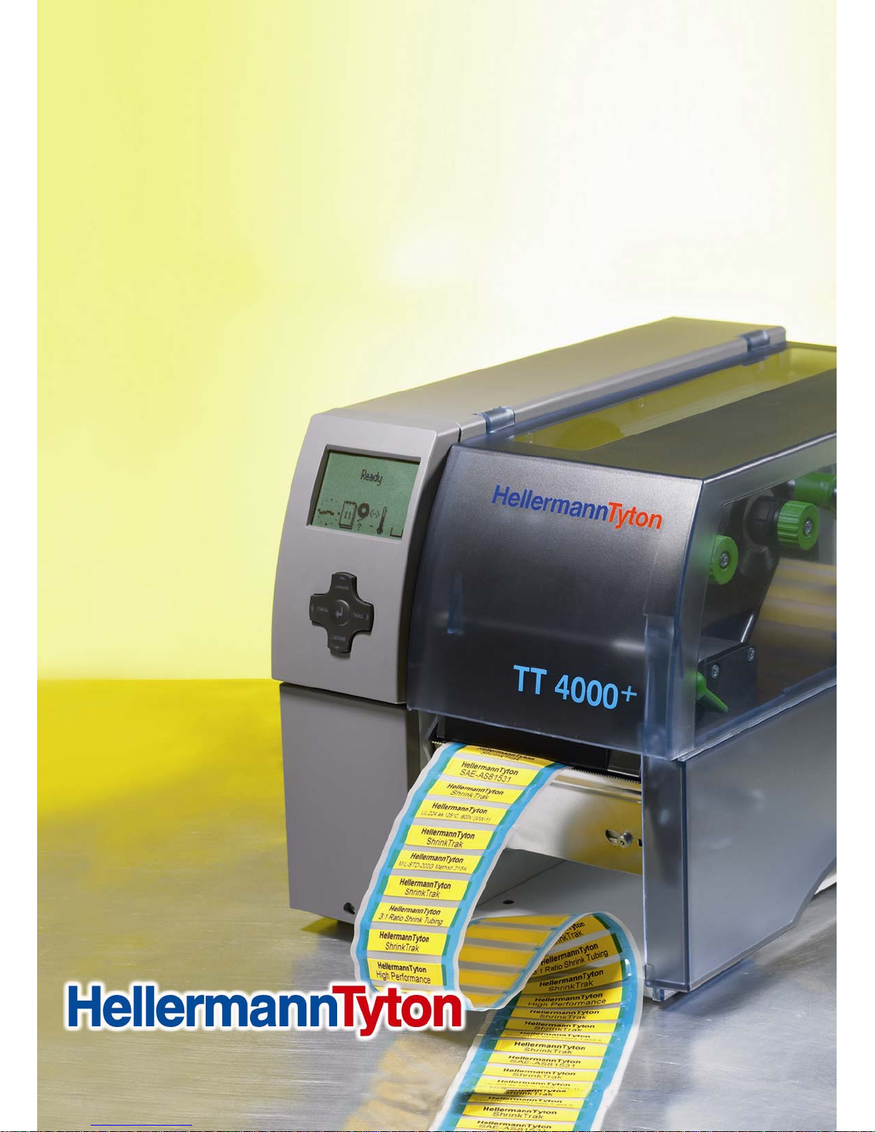
TT4000+
Thermal Transfer Printer
TT4000+ Series
User Manual
Stand: 08/09
Page 2

Users Manual for T4000+ Series 2
Operator’s Manual for the following products:
TT4000+300 dpi
TT4000+600 dpi
Issue: 10/2009
Copyright
This documentation as well as translation hereof are property of HellermannTyton.
The replication, conversion, duplication or divulgement of the whole manual or parts of it
for other intentions than its original intended purpose demand the previous written
authorization by HellermannTyton.
Trademark
Microsoft® is a registered trademark of the Microsoft Corporation.
Windows 2000®, 2003®, XP®, Vista® are registered trademarks of the Microsoft
Corporation.
TrueTypeTM is a registered trademark of Apple Computer, Inc.
Aktualität
Due to the constant further development of our products discrepancies between
documentation and product can occur.
For the latest update please check www.HellermannTyton.co.uk/downloads
Terms and conditions
Deliveries and performances are affected under the General conditions of sale of
HellermannTyton.
Page 3

Users Manual for T4000+ Series 3
1.
Information on the technical documentation __________________________________ 5
1.1. Structure and Navigation ____________________________________________ 5
1.2. Warning symbols and other identificational objects ________________________ 5
1.3. Intended Use _____________________________________________________ 6
2. Safety and Environment _________________________________________________ 7
2.1. Safety instructions _________________________________________________ 7
2.2. Environment ______________________________________________________ 8
3. Installation ____________________________________________________________ 9
3.1. Unpacking the Printer _______________________________________________ 9
3.2. Settin-up the Printer ________________________________________________ 9
3.2.1. Printer overview ______________________________________________ 10
3.2.2. Connecting the device _________________________________________ 11
3.2.3. Connection to the Power Supply _________________________________ 11
3.2.4. Connecting to a Computer or Computer Network_____________________ 11
3.3. Switching on the Device ____________________________________________ 12
4. Control panel_________________________________________________________ 13
4.1. Structure of the Control Panel _______________________________________ 13
4.2. Functions of the operating panel during printing__________________________ 14
4.2.1. Symbol indicators _____________________________________________ 14
4.2.2. Printer status_________________________________________________ 15
5. Loading media________________________________________________________ 17
5.1. Loading continuous labels or tubing from a roll __________________________ 17
5.1.1. Positioning the label roll on the roll retainer _________________________ 17
5.1.2. Inserting media strip into the print head ____________________________ 18
5.1.3. Settiing the Labels Sensor (Figures 7 & 8) __________________________ 18
5.2. Loading Fanfold Labels ____________________________________________ 19
5.3. Loading transfer ribbon_____________________________________________ 20
5.4. Setting the Feed Path of the Transfer Ribbon ___________________________ 21
5.5. Setting the Head Locking System_____________________________________ 21
5.6. Removing and installing the rewind guide plate, dispense plate or tear-off plate_ 22
6. Printing _____________________________________________________________ 23
6.1. Synchronization __________________________________________________ 23
6.2. Tear-Off mode ___________________________________________________ 23
6.3. Peel-Off mode (Option) ____________________________________________ 23
6.4. Internal rewinding (Option) __________________________________________ 23
7. Cleaning and basic maintenance _________________________________________ 24
Page 4

Users Manual for T4000+ Series 4
7.1. Cleaning information_______________________________________________ 24
7.2. Cleaning the Print Roller____________________________________________ 24
7.3. Cleaning the print head ____________________________________________ 24
8. Fault Correction_______________________________________________________ 25
8.1. Types of Errors ___________________________________________________ 25
8.2. Troubleshooting __________________________________________________ 25
8.3. Error Messages and Fault Corrections_________________________________ 26
Page 5
Users Manual for T4000+ Series 5
1. Information on the technical documentation
1.1. Structure and Navigation
Important information and instructions in this documentation are designated as follows:
The documentation for the thermal transfer printer TT4000+ is comprised of the following
parts:
• Operating Instructions
This is included in printed form in the scope of delivery and is directed toward persons who
operate the label printer and perform basic maintenance and service work on the printer
• Configuration Instructions
These are available on request at HellermannTyton and are directed toward persons who set
up, configure and perform more extensive maintenance and service work on the label printer.
• Service Instructions
These are available on request at HellermannTyton and are directed toward trained service
personnel who maintain and repair the label printer.
1.2. Warning symbols and other identification objects
Important information and instructions in this documentation are designated as follows:
DANGER!
Draws your attention to an exceptionally grave, impending danger to your health or life.
WARNING!
Indicates a hazardous situation that could lead to injuries or material damage.
ATTENTION!
Draws attention to possible dangers, material damage or loss of quality.
NOTICE!
Gives you tips. They make a working sequence easier or draw attention to important
working processes.
ENVIRONMENT!
Gives you tips on protecting the environment.
►
Handling instruction
Æ
Reference to section, position, illustration number or document.
Option (accessories, peripheral equipment, special fittings).
Menu
Information in the display.
Page 6

Users Manual for T4000+ Series 6
1.3. Intended Use
• The device is manufactured in accordance with the current technological status and the
recognized safety rules. However, danger to the life and limb of the user or third parties
and/or damage to the device and other tangible assets can arise during use.
• The device may only be used for its intended purpose and if it is in perfect working order, and
it must be used with regard to safety and dangers as stated in the operating manual
• The device printer is intended exclusively for printing suitable materials that have been
approved by the manufacturer. Any other use or use going beyond this shall be regarded as
improper use. The manufacturer/supplier shall not be liable for damage resulting from
unauthorized use; the user shall bear the risk alone.
• Usage for the intended purpose also includes complying with the operating manual, including
the manufacturer‘s maintenance recommendations and specifications.
NOTICE!
The complete documentation is included in the scope of delivery on CD ROM, and can also
currently be found in the Internet. www.HellermannTyton.co.uk/downloads
Page 7

Users Manual for T4000+ Series 7
2. Safety and Environment
Read these operating instructions carefully before using the label printer for the first time. The
operating instructions describe all of the functions of the label printer during operation. The
available functions depend on the version used for a specific job.
2.1. Safety instructions
• The device is configured for voltages of 100 to 240 V AC. It only has to be plugged into a
grounded socket.
• Only connect the device to other devices which have a protective low voltage.
• Switch off all affected devices (computer, printer, accessories) before connecting or
disconnecting.
• The device may only be used in a dry environment, do not expose it to moisture (sprays of
water, mists, etc.).
• Do not use the device in an explosive atmosphere.
• Do not use the device close to high-voltage power lines.
• If the device is operated with the cover open, ensure that people‘s clothing, hair, jewelry etc.
do not come into contact with the exposed rotating parts.
• The device or parts of it can become hot while printing. Do not touch during operation, and
allow to cool down before changing material and before disassembly.
• Risk of crushing when closing the cover. Touch the cover at the outside only. Do not reach
into the swivel range of the cover.
• Perform only those actions described in this operating manual. Work going beyond this may
only be performed by trained personnel or service technicians.
• Unauthorized interference with electronic modules or their software can cause malfunctions.
• Other unauthorized work on or modifications to the device can also endanger operational
safety.
• Always have service work done in a qualified workshop, where the personnel have the
technical knowledge and tools required to do the necessary work.
• There are various warning stickers on the device. They draw your attention to dangers.
Warning stickers must therefore not be removed, as then you and other people cannot be
aware of dangers and may be injured.
•
The maximum sound pressure level is less than 70 dB(A).
DANGER!
Danger to life and limb from power supply.
► Do not open the device casing.
Page 8

Users Manual for T4000+ Series 8
2.2. Environment
Obsolete devices contain valuable recyclable materials that should be sent for recycling.
► Send to suitable collection points, separately from residual waste. The modular construction
of the printer enables it to be easily disassembled into its component parts
► Send the parts for recycling.
The Electronic circuit board of the device is equipped with a lithium battery
► Take old batteries to collection boxes in shops or public waste disposal centres.
Page 9
Users Manual for T4000+ Series 9
3. Installation
3.1. Unpacking the Printer
Æ Lift the printer out of the box using the hand grips.
Æ Check the printer for damage which may have occurred during the transport.
Æ Please check the carton for completeness
Scope of delivery
• Thermal transfer Printer
• Empty ribbon reel mounted on the ribbon take-up hub
• Tear-off plate
• Power Cable
• Drivers on CD-ROM
• USB-cable
NOTICE!
Please keep the original packaging in case the printer must be returned.
3.2. Setting-up the Printer
DANGER!
The device and printing materials will be damaged by moisture and wetness.
► Set up label printers only in dry locations protected from splash water.
► Set up printer on a level surface
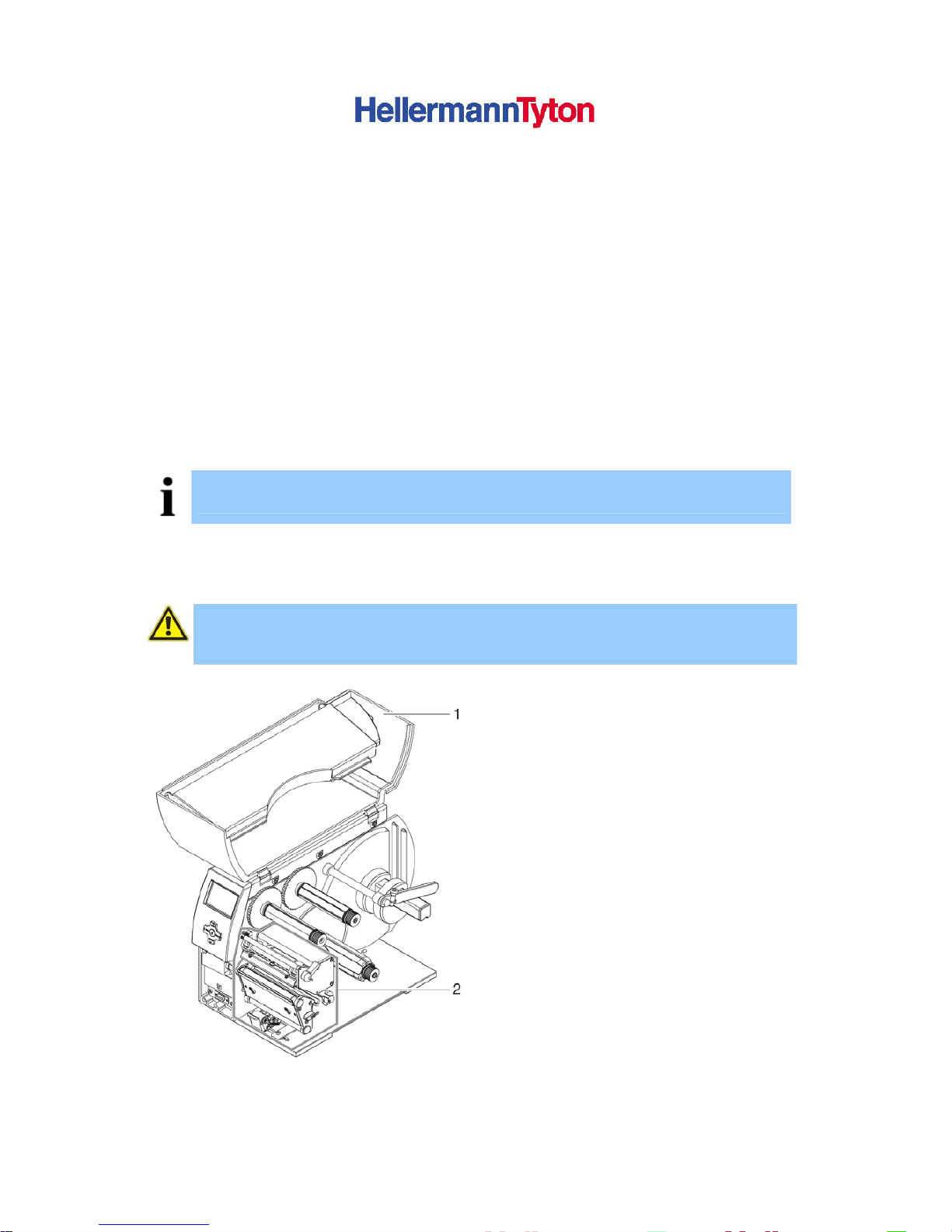
► Open the cover (1) of the printer
► Remove foam transportation safeguards
near the print head (2)
Figure 1 Remove transportation safeguards
Page 10
Users Manual for T4000+ Series 10
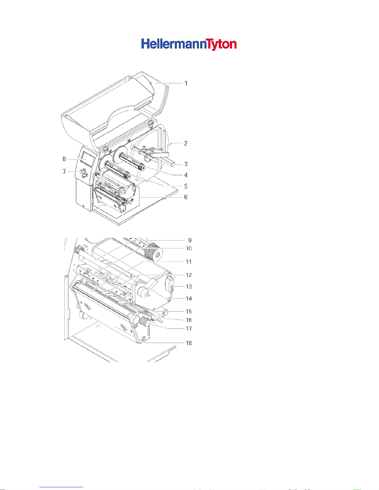
3.2.1. Printer overview
(1) Cover
(2) Margin Stops
(3) Roll Retainer
(4) Ribbon supply hub
(5) Ribbon take-up hub
(6) Print mechanics
(7) Navigator pad
(8) Display
Figure 2 Overview
(9) Ribbon deflection roller
(10) Print head retainer with print head
(11) Print roller
(12) Guides
(13) Allen Key
(14) Print head locking lever
(15) Guide roller
(16) Label sensor
(17) Knob for guide adjustment
(18) Tear-off plate
Figure 3 Print mechanics
Page 11
Users Manual for T4000+ Series 11
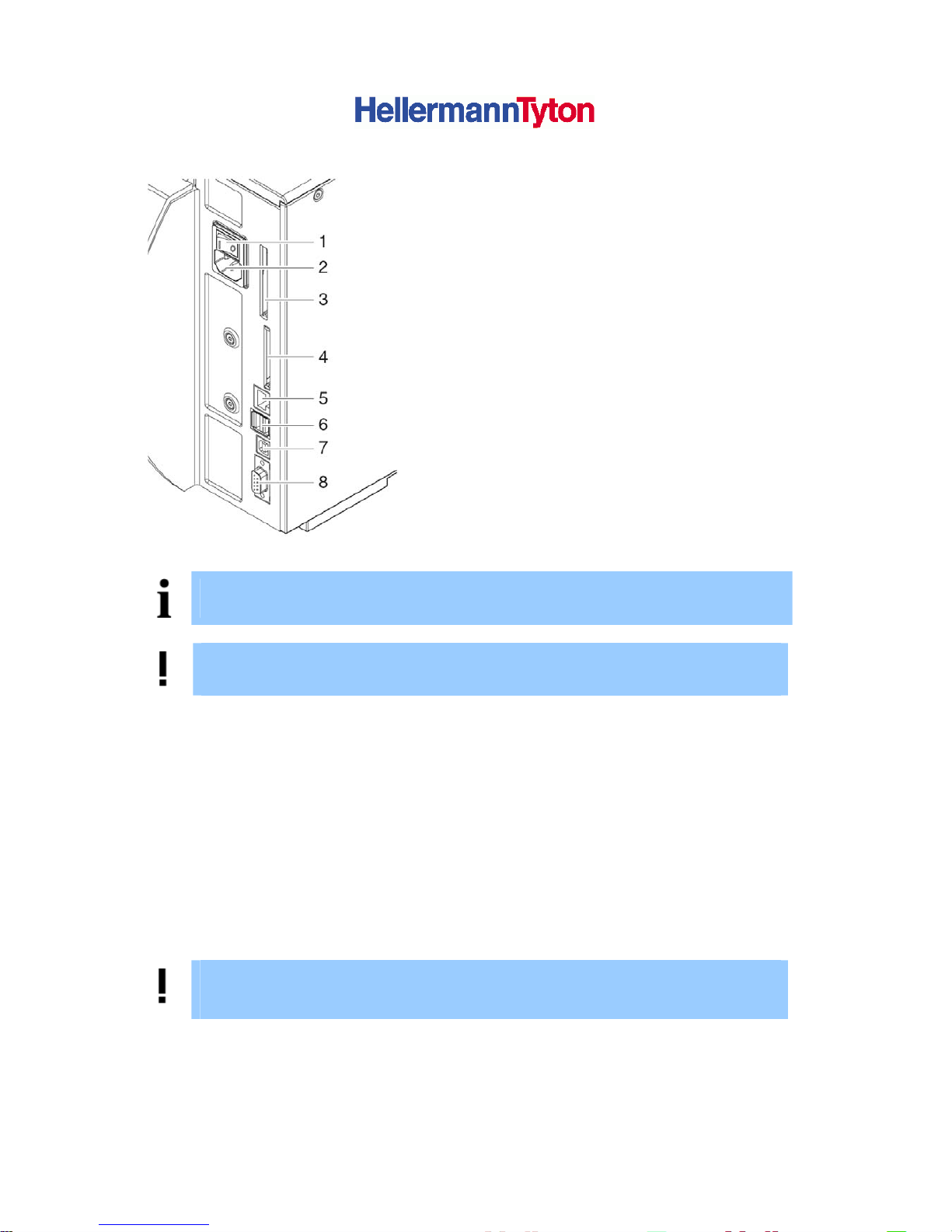
3.2.2. Connecting the device
(1) Power switch
(2) Power connection jack
(3) Slot for PC-Card Type II
(4) Interface for Memory Card
(5) E thernet 10/100 Base-T
(6) 2 USB master ports for keyboard,
scanner or service key
(7) USB-High-Speed slave port
(8) Serial RS232 C port
Figure 4 Connections
NOTICE!
Please keep the original packaging in case the printer must be returned.
DANGER!
The device and printing materials will be damaged by moisture and wetness.
► Set up label printers only in dry locations protected from splash water.
3.2.3. Connection to the Power Supply
The printer is equipped with a wide area power unit. The device can be operated with a supply
voltage of 230 V~/50 Hz or 115 V~/60 Hz without adjustment.
Make sure that the device is switched off!
(1) Plug the power cable into the power connection socket (2)
(2) Plug the power cable into a grounded socket.
3.2.4. Connecting to a Computer or Computer Network
ATTENTION!
Inadequate or no grounding can cause malfunctions during operations.
Ensure that all computers and cables connected to the label printer are grounded.
► Connect the label printer to a computer or network by a suitable cable.
For details of the configuration of the individual interfaces Æ Configuration Manual.
Page 12

Users Manual for T4000+ Series 12
3.3. Switching on the Device
When all connections have been made:
► Switch the printer on at the power switch (Figure 4, Number 1).
The printer performs a system test, and then shows the system status Ready in the display
(Figure 5, Number 1)
If an error occurs during the system test, the symbol
and type of error are displayed.
Page 13
Users Manual for T4000+ Series 13
4. Control panel
The user can control the operation of the printer with the control panel, for example:
• Issuing, interrupting, continuing and cancelling the print jobs
• Setting printing parameters, e.g. heat level of the print head, print speed, interface
configuration language and time of day (Æ Configuration Manual)
• Start the test functions (Æ Configuration Menu)
• Control stand alone operation with a memory module (Æ Configuration Menu)
• Update the Firmware (Æ Configuration Menu)
Many functions and settings can also be controlled by software applications or by direct
programming with a computer using the printer’s own commands. Æ Programming Manual for
details.
Settings made on the control panel make the basic settings of the label printer.
NOTICE!
It is advantageous, whenever possible, to make adaptations to various print jobs in the
professional label editing software Tagprint Pro.
4.1. Structure of the Control Panel
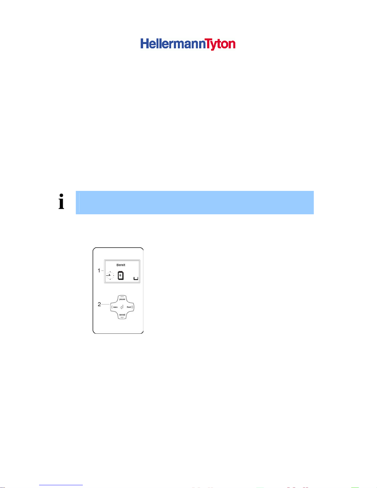
1. Graphic Display
2. Navigator Pad
Figure 5 Control Panel
The graphical menu informs the user about the current status of the Printer and its print jobs,
informs about errors and shows the printers settings in the menu.
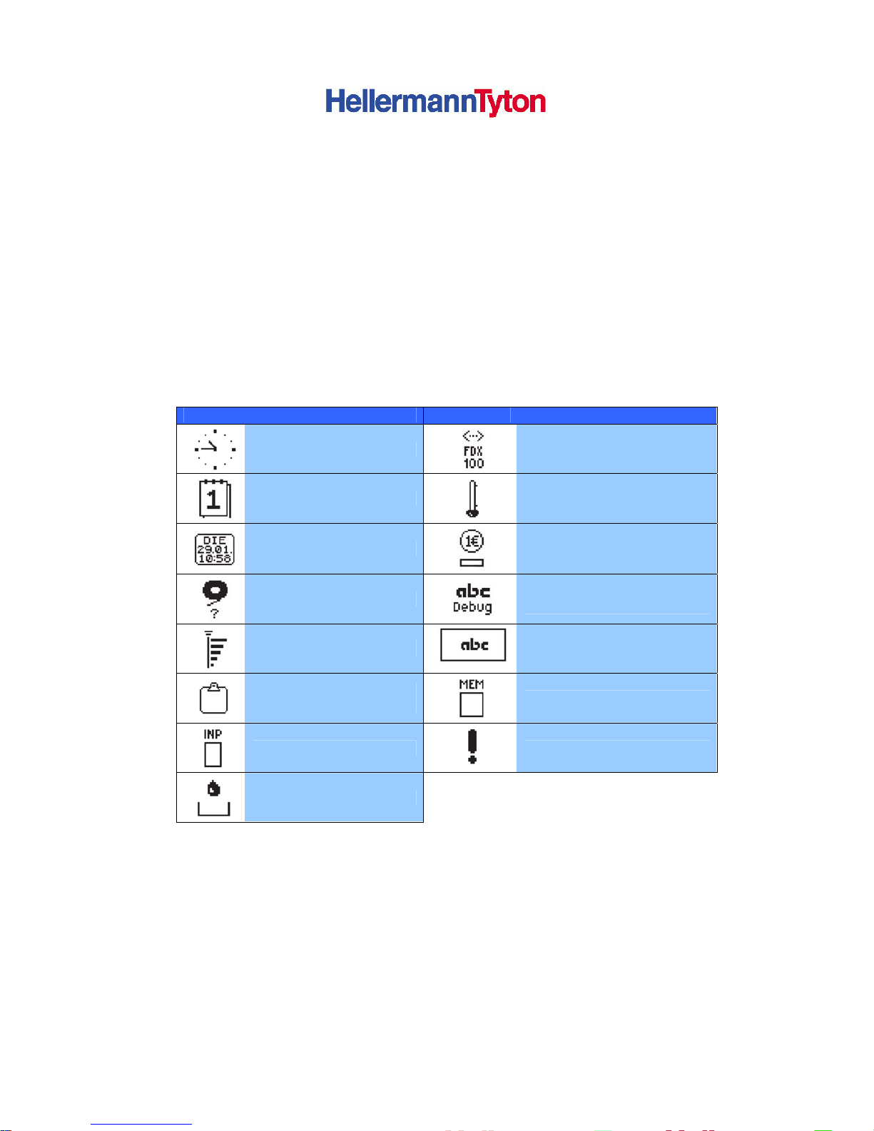
The symbols shown in the following table may appear in the status line of the display, depending
on the printer configuration. They enable the current printer status to be seen quickly. For the
configuration of the status line Æ Configuration Manual.
During the online menu of the printer the active functions light up white (e.g. Menu or Feed)
Active Functions light up orange in the offline menu (Arrow, Key ).
Page 14
Users Manual for T4000+ Series 14
Key function of the
Keys: Pause, cancel, menu, feed:
Arrows: Cursor shift to up, down, left or right within the printer menu
Key : Parameter setting within the printer menu, receive concise information about current
error.
4.2. Functions of the operating panel during printing
4.2.1. Symbol indicators
The symbol indicators shown in the following table can appear on the status line of the screen,
depending on the configuration of the printer. They inform you of the current status of the printer
at a glance. For configuration of the status line, see the “Configuration Instructions“.
Symbol Meaning Symbol Meaning
Time
Ethernet Status
Date
Print head temperature
Digtial clock
PPP-credit
Ribbon Supply
Debug window for ABCprogrammes
Wi-Fi signal strength
Control of the lower display
line is handed over to an abc
program
User memory in the clock
circuit
Used memory
Input buffer
Access to memory card
Printer is receiving data
Table 1 Indicator symbols during printing
Page 15
Users Manual for T4000+ Series 15
4.2.2. Printer status
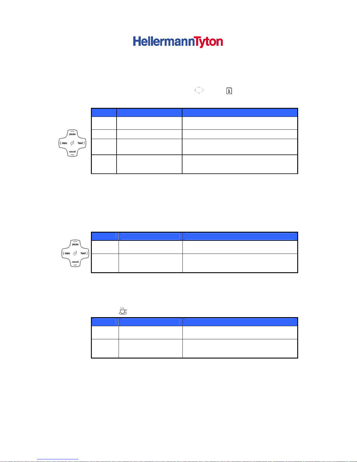
• Mode Ready
The printer is ready and can receive data. The display shows the text Ready and the
configured symbol indicators, such as time
and date .
Button Label Function
menu illuminates go to offline menu (see “Configuration
Instructions“)
feed illuminates advances an empty label
pause Illuminates once a print
job is complete
repeat printing of last label
cancel illuminates clear print buffer,
repeated printing of the last label is then not
possible
Table 2 Functions in Ready mode
• Mode Printing Label
The printer is carrying out a print job. Data transfer for a new print job is possible in
'Printing' mode. The new print job starts once the preceding job is completed.
The display shows the text Printing Label and the number of the printed label within
the print.
Button
Label Function
pause illuminates
pause print job,
printer switches to Pause mode
cancel illuminates
press briefly → cancel current print job
press and hold → cancel current print job
and delete all print jobs
Table 3 Functions in Printing Label mode
• Mode Pause
The print job has been interrupted by the operator. The display shows the text Pause and
the symbol
Button Label Function
pause illuminates
continue print job,
printer switches to Printing Label mode
cancel illuminates
press briefly → cancel current print job
press and hold → cancel current print job
and delete all print jobs
Table 4 Functions in Pause mode
Page 16
Users Manual for T4000+ Series 16
• Mode Fault - correctable
An error that can be remedied by the operator without canceling the print job has
occurred. he print job can be continued once the error is remedied. The display
shows the symbol , the error type and the number of labels still to be printed.
Button Label Function
pause flashes continue print job after error recovery,
printer switches to Printing Label
mode
cancel illuminates press briefly → cancel current print job
press and hold → cancel current print job
and delete all print jobs
Button illuminates
call up help – brief information on error
recovery is displayed
Table 5 Functions in 'error which can be remedied' mode
• Mode
Fault - irrecoverable
An error that cannot be remedied without cancelling the print job has occurred. The
display shows the symbol , the error type and the number of labels still to be
printed.
Button Label Function
cancel flashes press briefly → cancel current print job
press and hold → cancel current print job
and delete all print jobs
Button illuminates
call up help – brief information on error
recovery is displayed
Table 6 Functions in 'error which cannot be remedied' mode
• Mode System error
If an error has occurred while the system was starting up, the symbol and the error
type are displayed.
⇒ Switch off printer via the power switch and switch it on again.
-or
⇒ Push the cancel button.
⇒ If the error occurs repeatedly, notify the Service Department.
Page 17
Users Manual for T4000+ Series 17
5. Loading media
NOTICE!
For adjustments and simple installation work, use the accompanying hexagonal
wrench located in the bottom section of the print unit. See Figure 4, Item 8. No other
tools are required for the work described here.
5.1. Loading continuous labels or tubing from a roll
5.1.1. Positioning the label roll on the roll retainer
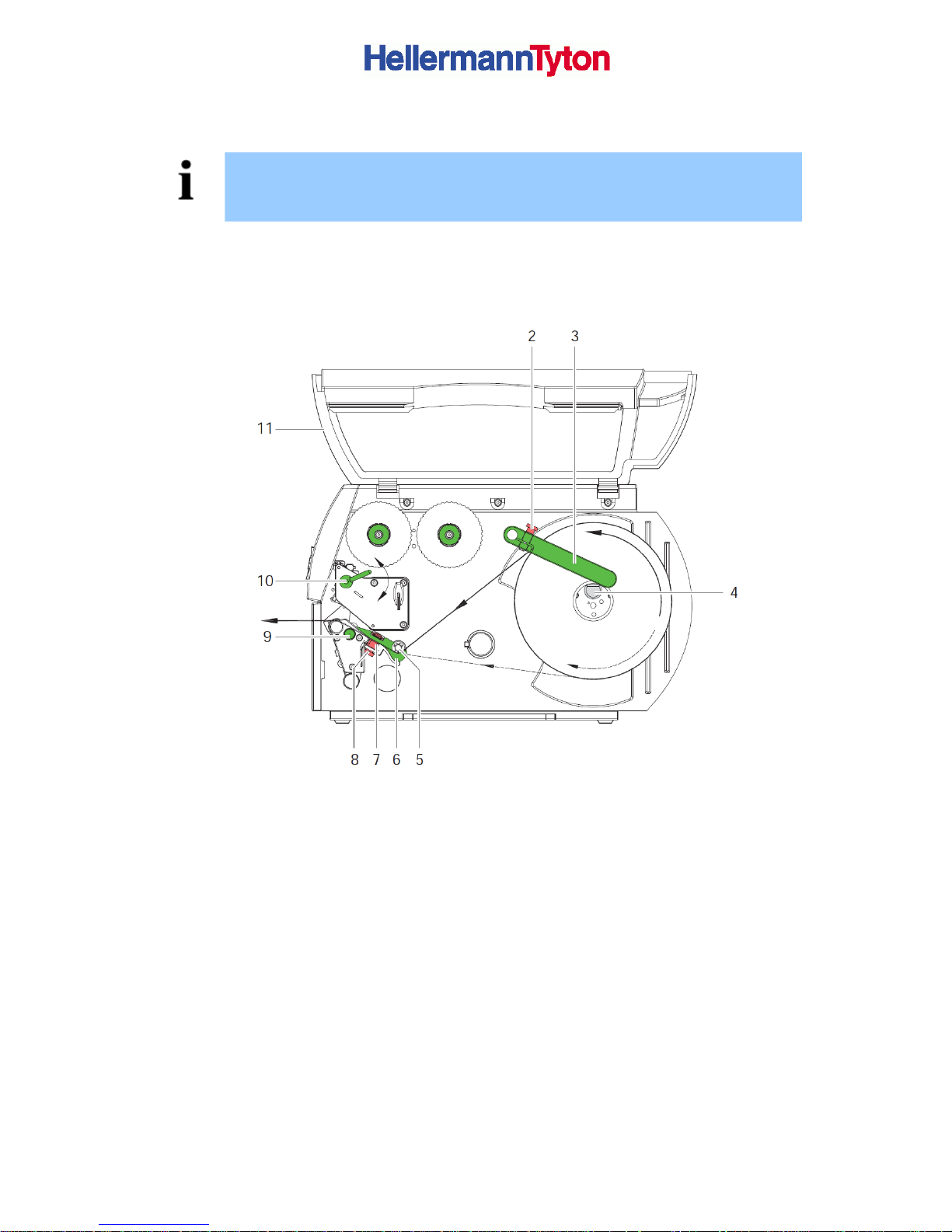
Figure 6 Loading labels from a roll
1. Open cover (11).
2. Loosen knurled screw (2) and swivel guide (3) upward and push it all the way out.
3. Load label roll on the roll retainer in such a way that the labels can be inserted into the
print head in the right position. The printing side of the labels must be visible from
above.
4. Supplying longer label strips approx. 40 cm
5. Push label roll until it contacts the housing wall.
6. Swivel guide (3) downward onto the roll retainer (4) and push it against the label roll so
that it rests against the supplying media.
7. Tighten knurled screw (2).
Page 18
Users Manual for T4000+ Series 18
5.1.2. Inserting media strip into the print head
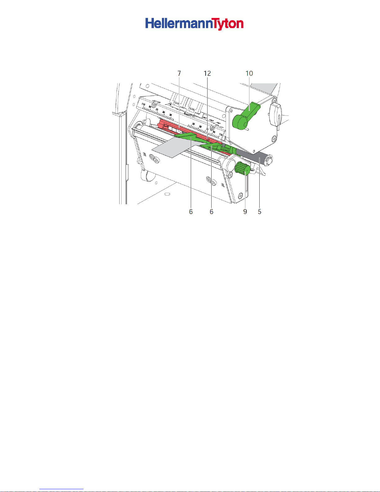
Figure 7 Inserting a media strip into the print head
1. Turn lever (10) counter clockwise to lift the print head.
2. Move guides (6) apart with the knob (9) until the media can pass between them.
3. Push media strip below the guide roller (5) between the guides (6).
4. Guide media strip through the label sensor (12) in such a way that it leaves the print
mechanics between print head (10, fig 3) and the print roller (11, fig 2).
5. Move guides (6) against the edges of the material by turning the knob (9).
5.1.3. Setting the Labels Sensor (Figures 7 & 8)
The label sensor (7, fig. 7) can be shifted perpendicular to the direction of paper flow for
adaptation to the media. The sensor unit of the label sensor is visible from the front through
the print unit and is marked with an indentation (12, fig. 7) in the label sensor retainer. When
the printer is switched on, a yellow LED illuminates the sensor position.
► Loosen the knurled knob (8, fig 6) and position label sensor by moving the knurled knob in
such a way that the sensor can detect the label gap or a reflex or cut-out mark.
► - or, if the labels deviate from a rectangular shape, -
► Align label sensor with the front edge of the label in the direction of paper flow.
► Re-tighten the knurled knob.
► Turn lever (10, fig. 7) clockwise to lock the print head.
Page 19
Users Manual for T4000+ Series 19
5.2. Loading Fanfold Labels
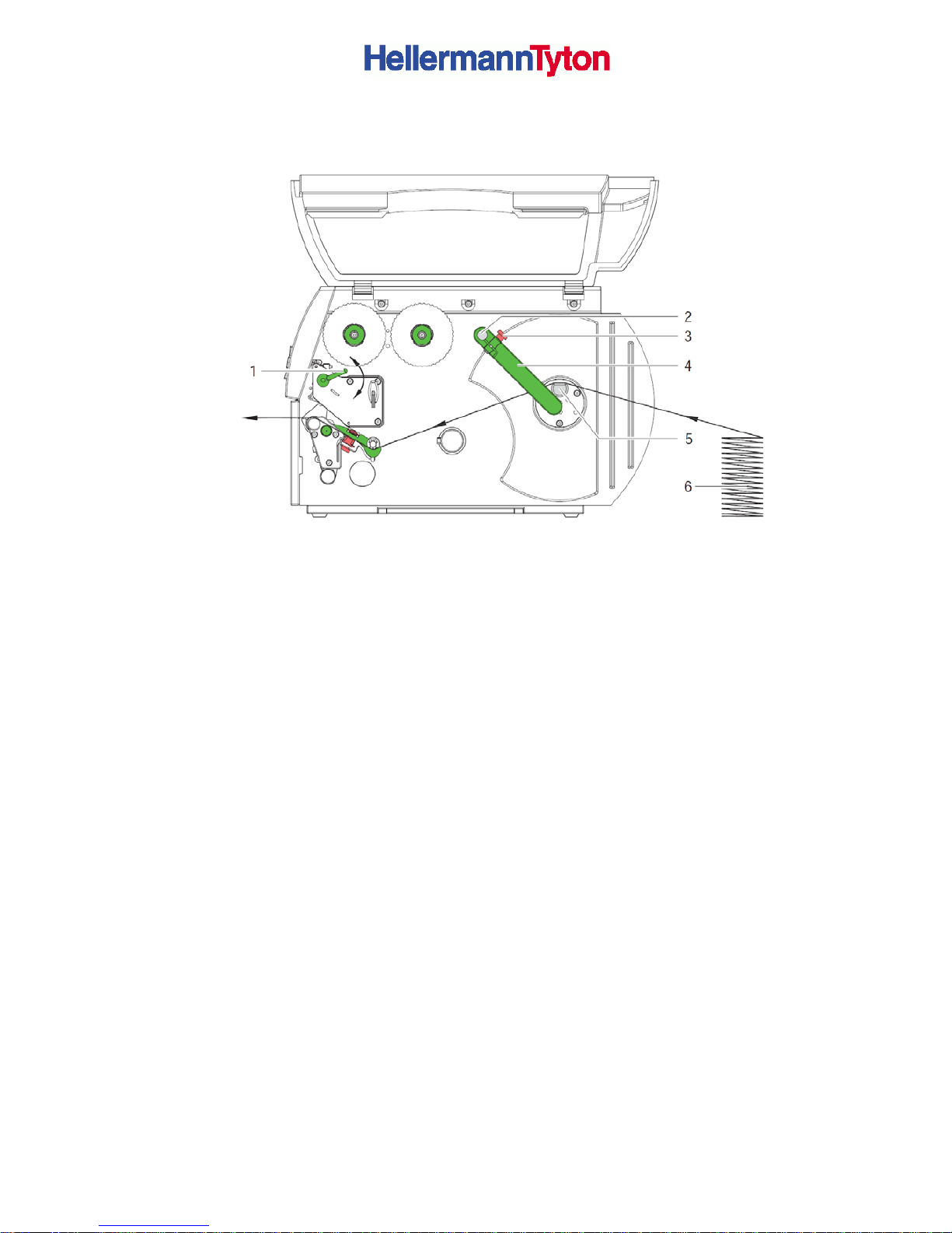
Figure 8 Loading fanfold labels
1. Loosen knurled screw (3) and slide guide (2) outward completely and swivel it downward
past the roll retainer (5).
2. Position label stack (6) behind the printer. Ensure that the labels on the strip are visible
from above.
3. Guide label strip to print unit via the roll retainer (5).
4. Push guide (4) against the label strip, swivel it upward against the roll retainer and tighten
knurled screw (3).
5. Insert label strip into print head (see 5.1.2 on Page 16).
6. Set label sensor (see 5.1.3 on page 6).
8. Turn lever (1) clockwise to lock the print head.
Page 20
Users Manual for T4000+ Series 20
5.3. Loading transfer ribbon
NOTICE!
With direct thermal printing, do not load a transfer ribbon; if one has already been loaded,
remove it.
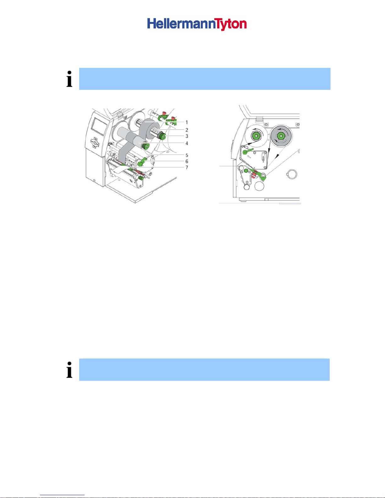
Figure 9 loading
Figure 10 Feed path of transfer ribbon
1. Clean print head before loading the transfer ribbon (see 7.3 on page 24)
2. Turn lever (4) anti clockwise to lift the print head.
3. Slide transfer ribbon roll (1) onto the ribbon supply hub (2) until it stops and so that the
colour coating of the ribbon faces downward when being unwound. No rotation direction
is specified for the ribbon supply hub (2).
4. Hold transfer ribbon roll (2) firmly and turn knob on ribbon supply hub (3) anti clockwise
until the transfer ribbon roll is secured.
5. Slide suitable transfer ribbon core onto the transfer ribbon take-up hub (4) and secure it
in the same way.
6. Guide transfer ribbon through the print unit as shown in Figure 10.
7.
Secure starting end of transfer ribbon to the transfer ribbon core (4) with adhesive tape.
Ensure anti clockwise rotation direction of the transfer ribbon take-up hub here.
8.
Turn transfer ribbon take-up hub (4) anti clockwise to smooth out the feed path of the
transfer ribbon.
9.
Turn lever (6) clockwise to lock the print head.
NOTICE!
To rewind the transfer ribbon use a core with a width between the width of the supply roll and
115 mm.
Page 21
Users Manual for T4000+ Series 21
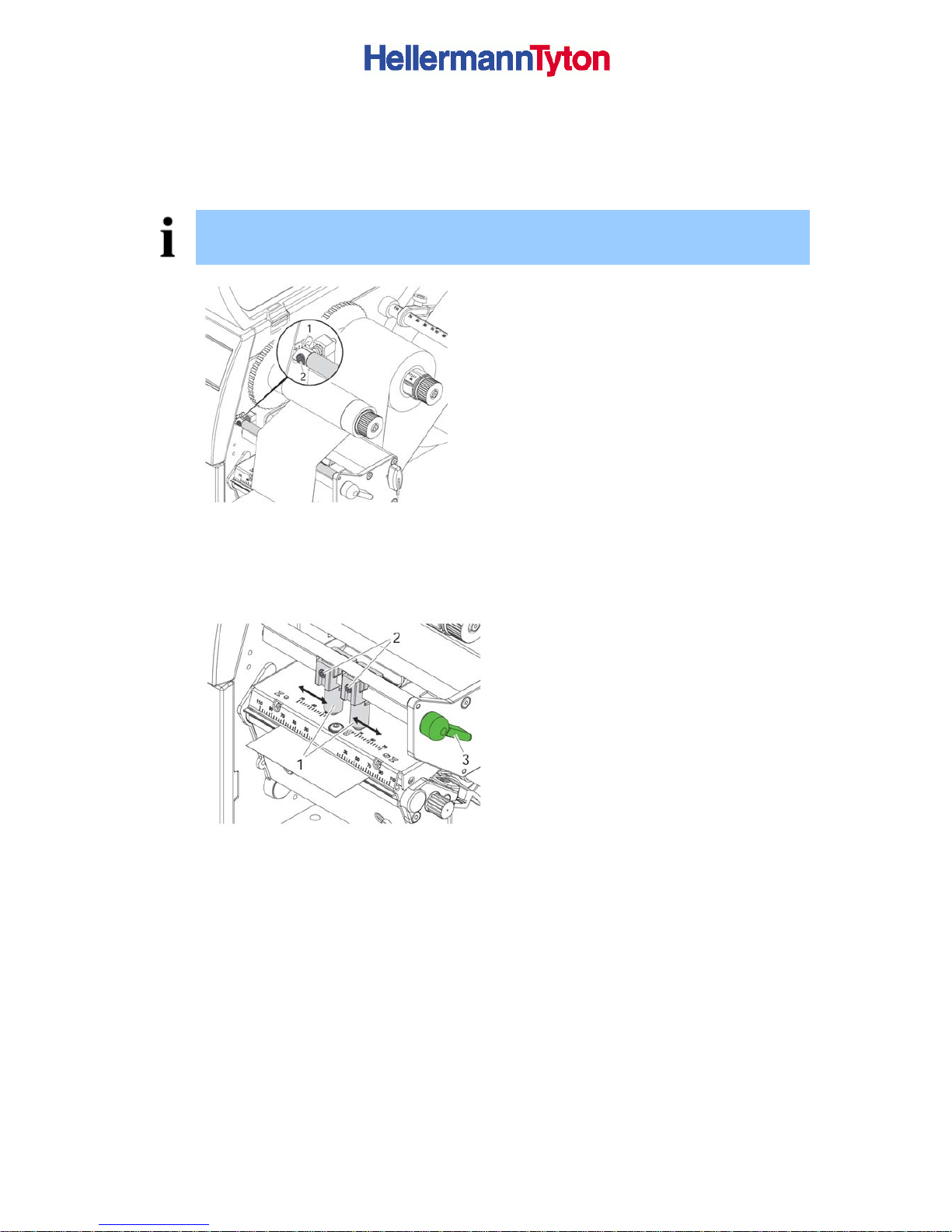
5.4. Setting the Feed Path of the Transfer Ribbon
Transfer ribbon wrinkling can lead to print image errors. Transfer ribbon deflection can be
adjusted so as to prevent wrinkles.
NOTICE!
The adjustment is best carried out during printing.
1. Read current setting on the scale (1)
and record if necessary.
2. Turn screw (2) with Allen key and
observe the behaviour of the ribbon. In
the + direction, the inner edge of the
ribbon is tightened, and the outer edge
is tightened in the - direction.
Figure 11 Setting the feed path of the transfer ribbon
5.5. Setting the Head Locking System
The print head is pushed on via two
plungers (1). In the basic setting the
plungers are set in the middle of the print
head retainer. This setting can be used for
the most applications.
3. If the print density decreases in the
outer areas when using very large
media, the plungers can be displaced :
4. Turn lever (3) clockwise to lock the print
head.
5. Loosen threaded pins (2) at the plungers
(1) with Allen key.
6. Displace plungers symmetrically as
necessary maximal to the scale value
70.
7. Tighten the threaded pins (2).
Figure 12 Setting the head locking system
Page 22
Users Manual for T4000+ Series 22
5.6. Removing and installing the rewi nd guide plate, dispense plate or
tear-off plate
To convert the printer for use in another operating mode, a rewind guide plate, a dispense
plate or a tear-off plate may need to be installed.
ATTENTION!
For printer versions with a locking system on the rewind assist roller, the locking system on
the rewind assist roller must be removed (see 5.7, page 21) for operation in Rewind mode
before installation of the rewind guide plate.
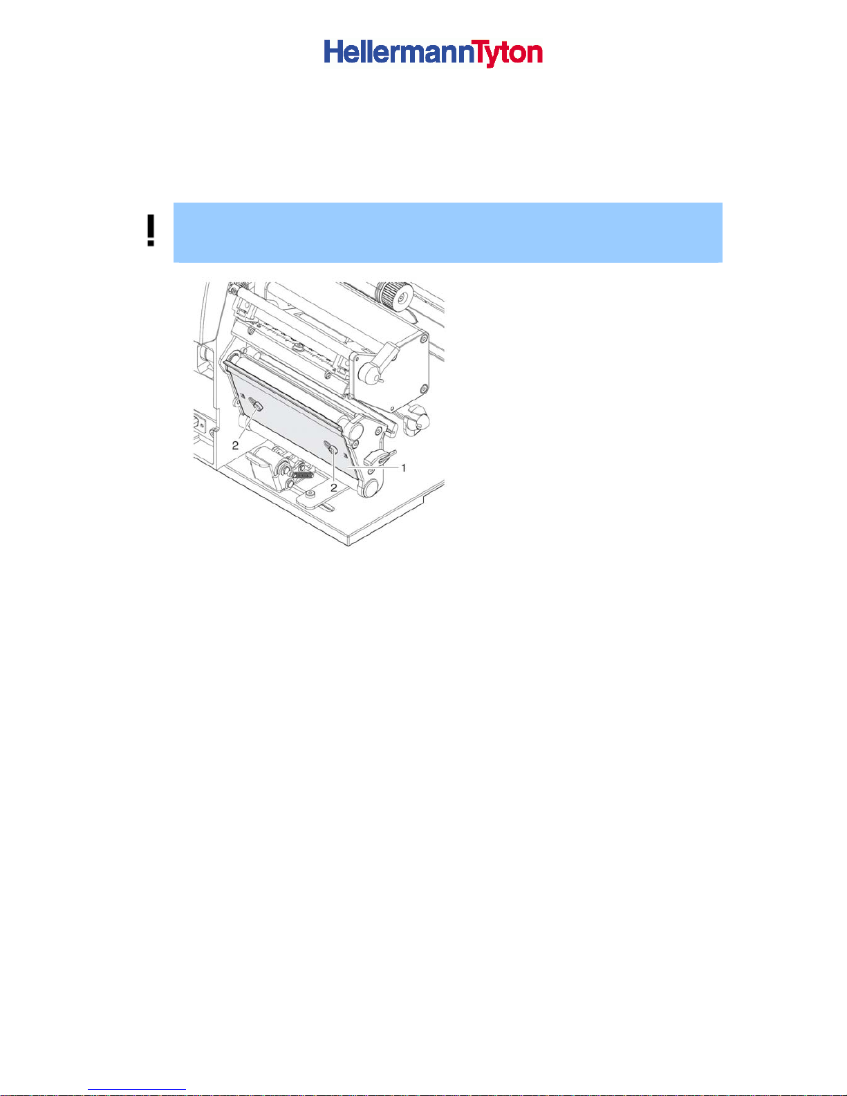
Removing a plate
1. Loosen screws (2) several turns.
2. Slide plate (1) to the right and remove it.
Installing a plate
3. Place plate (1) onto the screws (2) and
slide to the left completely
4. Tighten screws (2).
Figure 13 Removing and installing tear-off
plate
Page 23

Users Manual for T4000+ Series 23
6. Printing
ATTENTION!
The print head can be damaged if handled improperly!
⇒ Do not touch the bottom of the print head with your fingers or sharp objects.
⇒ Ensure that the labels are clean.
⇒ Ensure smooth label surfaces. Raw labels are like emery and reduce the service life
of the print head.
⇒ Print at the lowest possible print head temperature.
6.1. Synchronization
The printer is ready for operation when all connections have been made, the labels and, if
necessary the transfer ribbon, have been loaded and the print head is locked. For details on
printer configuration, see the ‘Configuration instructions’.
After loading the label medium, synchronization is necessary. During synchronization, the
printer automatically determines the length of the loaded labels and sets label advancement
accordingly.
1. Press the feed button to start synchronization.
2. Remove empty labels after synchronization.
The printer is synchronized with the loaded label medium.
NOTICE!
Synchronization is not necessary if the print head was not opened between different print jobs,
even if the printer was switched off.
6.2. Tear-Off mode
In Tear-Off mode, labels or continuous media are printed. After printing, the label strip is
separated by hand. The label printer is equipped with a tear-off plate for this. Optionally, the
label can be cut off or label strips can be wound up externally.
6.3. Peel-Off mode (Option)
In Peel-Off mode, the labels are automatically peeled off the carrier medium after printing and
presented for removal. The label printer is equipped with a dispense plate and a peel-off
sensor or peel-off adapter. The carrier medium is wound up inside the printer.
6.4. Internal rewinding (Option)
The labels are wound up internally after printing with the carrier medium for later use. The
label printer is equipped with a rewind guide plate for this.
Page 24

Users Manual for T4000+ Series 24
7. Cleaning and basic maintenance
7.1. Cleaning information
DANGER!
Risk of death via electric shock!
► Disconnect the printer from the power supply before performing any maintenance work.
The label printer requires very little maintenance.
It is important to clean the thermal print head regularly. This guarantees a consistently good
printed image and plays a major part in preventing premature wear of the print head.
Otherwise, the maintenance is limited to monthly cleaning of the device.
ATTENTION!
The printer can be damaged by aggressive cleansers.
Do not use abrasive cleaners or solvents for cleaning the external surfaces or modules.
► Remove dust and paper fluff from the print area with a soft brush or vacuum cleaner.
► The cover of the printer can be cleaned with a standard cleanser.
7.2. Cleaning the Print Roller
Accumulations of dirt on the print roller may impair the media transport and the print quality.
► Lift the print head.
► Remove labels and transfer ribbon from the printer.
► Remove deposits with roller cleaner and a soft cloth.
► If the roller appears damaged, replace it Æ Service Manual.
7.3. Cleaning the print head
Cleaning intervals: direct thermal printing - every media roll change
thermal transfer printing - every ribbon roll change
Substances may accumulate on the print head during printing and adversely affect printing,
e.g. differences in contrast or vertical stripes.
ATTENTION!
Print head can be damaged!
Do not use sharp or hard objects to clean the print head.
Do not touch protective glass layer of the print head.
ATTENTION!
Risk of injury from the hot print head line.
Ensure that the print head has cooled down before starting cleaning.
► Lift the print head.
► Remove labels and transfer ribbon from the printer.
► Clean print head surface with special cleaning pen or a cotton swab dipped in pure
alcohol.
► Allow print head to dry for 2–3 minutes before commissioning the printer.
Page 25
Users Manual for T4000+ Series 25
8. Fault Correction
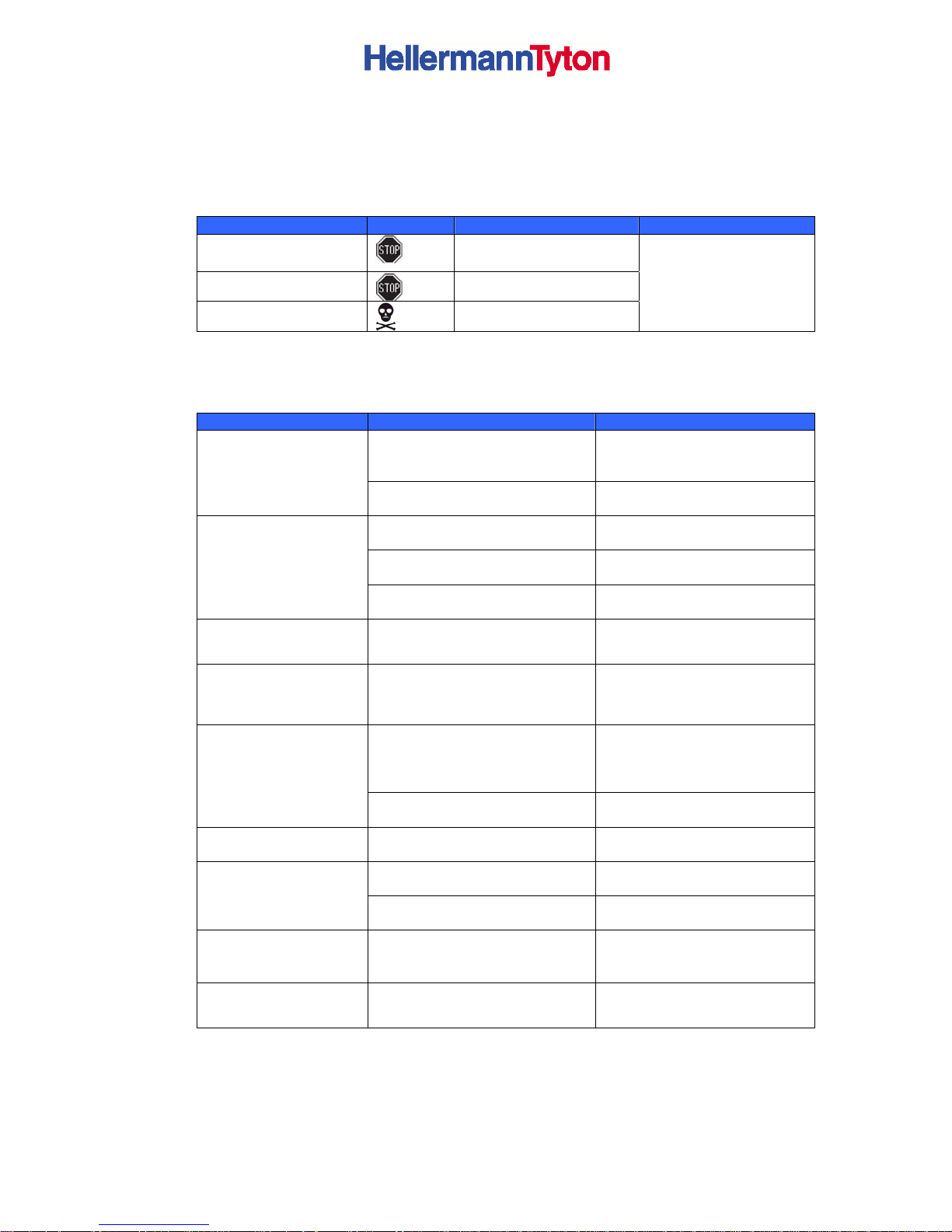
8.1. Types of Errors
The diagnostic system indicates on the screen if an error has occurred. The printer is set into
one of the three possible error states according to the type of error.
State Display Button Comment
Correctable error
pause flashes
cancel illuminates
Irrecoverable error
cancel flashes
Critical fault
-
Æ 4.2.2, page 15
Table 7 Types of Errors
8.2. Troubleshooting
Problem
Cause Comment
Transfer ribbon deflection not
adjusted
Adjust the transfer ribbon
deflection
Æ 5.4 on page21
Transfer ribbon
creases
Transfer ribbon too wide Use a transfer ribbon slightly
wider than the width of label.
Print head is dirty Clean the print head
Æ7.3 on page 24
Temperature too high Decrease temperature via
software.
Print image has
smears or voids
Unsuitable combination of labels
and transfer ribbon
Use different type of ribbon.
Printer does not
stop after transfer
ribbon runs out
Thermal printing is chosen in the
software
Change to thermal transfer
printing.
Printer prints a
sequence of
characters instead
of the label format
Printer is in ASCII dump mode Cancel the ASCII dump mode.
Transfer ribbon incorrectly
inserted
Check and, if necessary,
correct the transfer ribbon web
and the orientation of the label
side.
Printer transports
label media, but
transfer ribbon
does not move
Unsuitable combination of labels
and transfer ribbon
Use different type of ribbon.
Printer only prints
each second label
Setting of the size in the
software is too large
Change the size in the
software.
Print head is dirty Clean the print head
Æ 7.3 on page 24
Vertical white
lines in the print
image
Print head is defective (failure of
heat elements)
Change the print head.
Horizontal white
lines in the print
image
Printer is used with the
backfeed > smart
In the cut or peel-off node
Set the backfeed > always
in the setup.
ÆConfiguration Manual.
Print image is
irregular, one side
is lighter
Print head is dirty Clean the print head
Æ 7.3 on page 24
Table 6 Problem solution
Page 26
Users Manual for T4000+ Series 26
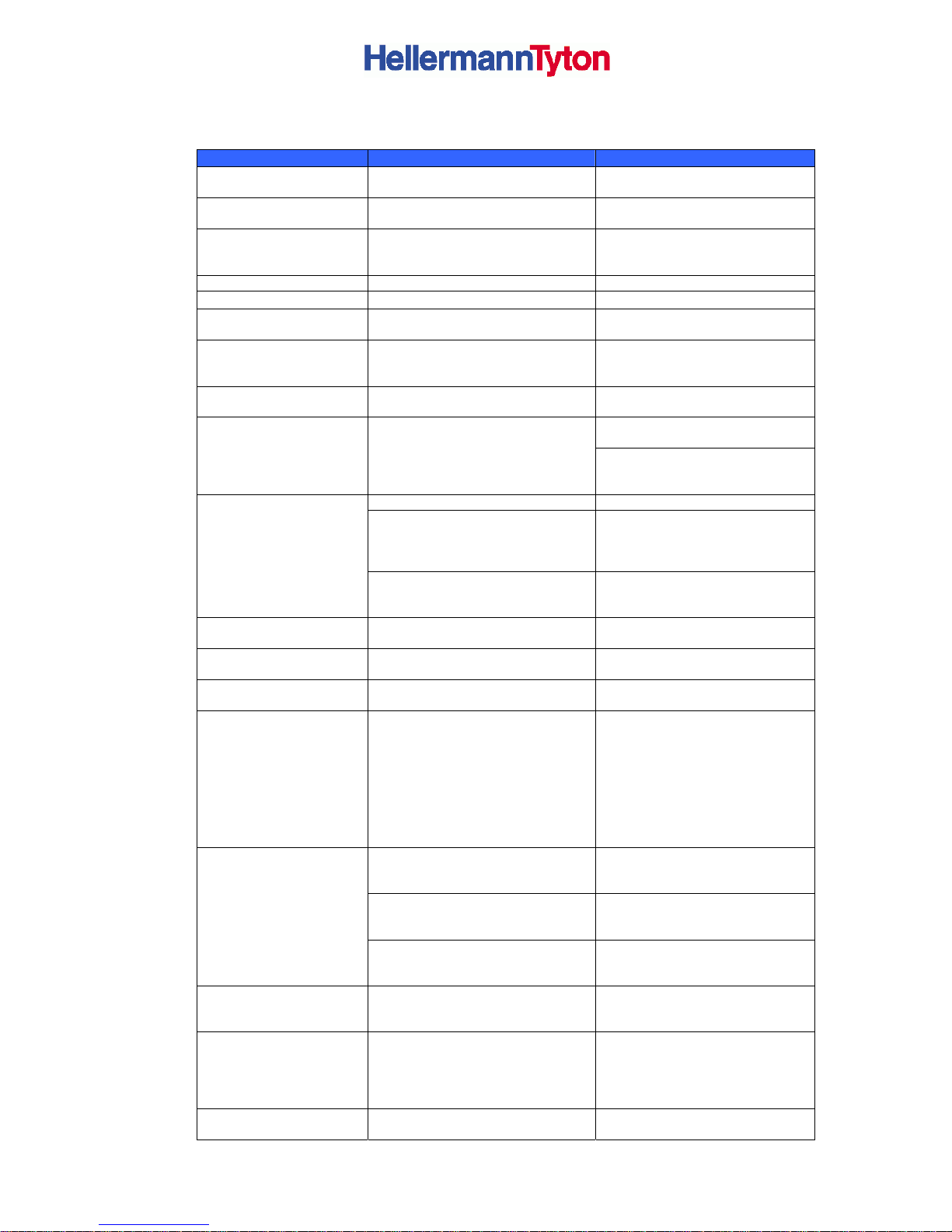
8.3. Error Messages and Fault Corrections
Error message Cause Comment
ADC malfunction
Hardware error Switch the printer off and then on.
If error recurs call service.
Barcode too big
The barcode is too big for the
allocated area of the label
Reduce the size of the barcode or
move it.
Barcode error
Invalid barcode content, e.g.
alphanumeric characters in a
numerical barcode
Correct the barcode content.
Battery low
Battery of the PC card is flat Replace battery in the PC card.
File not found
Requested file is not on the card Check the contents of the card.
Head error
Hardware error Switch the printer off and then on.
If error recurs replace print head.
Wrong revision
Error when updating the firmware.
Firmware not compatible with the
hardware version.
Load the compatible firmware.
Name exists
Duplicate usage of field name in the
direct programming
Correct programming.
For direct thermal printing remove
ribbon.
Remove ribbon
Transfer ribbon is loaded although
the printer is set to direct thermal
printing
For thermal transfer printing set
the printer in the configuration or in
the software to transfer printing.
Out of transfer ribbon Insert new transfer ribbon.
Transfer ribbon melted during
printing
Cancel current print job. Change
heat level via software. Clean the
print head Æ 7.3 on page 21. Load
transfer ribbon. Restart print job.
Out of ribbon
The transfer is loaded with thermal
labels, but the software is set to
transfer printing
Cancel current print job. Set
software to direct thermal printing.
Restart print job.
FPGA malfunction
Hardware error Switch the printer off and then on.
If error recurs call service.
Device not conn.
Programming addresses a nonexistent device
Either connect this device or
correct the programming.
No record found
Refers to the optional memory card;
Database access error
Check programming and card
contents.
No DHCP server
Printer is configured for DHCP, but
there is no DHCP server, or the
DHCP server is currently not
available.
Switch off DHCP in the
configuration, and assign a fixed
IP address. Please contact your
network administrator.
There are labels missing on the
label material
Press pause key repeatedly until
printer is recognizes the next label
on the material.
The label format as set in the
software does not correspond with
the real label format
Cancel current print job.
Change the label format set in the
software. Restart print job.
No label found
Printer is loaded with continuous
paper, but the software is set on
labels
Cancel current print job.
Change the label format set in the
software. Restart print job.
No Link
No network link Check network cable and
connector. Please contact your
network administrator.
No SMTP server
The printer is configured for SMTP,
but there is no SMTP server, or the
SMTP server is currently not
available.
Switch off SMTP in the
configuration. Caution! Then a
warning cannot be sent by email.
Please contact your network
administrator.
No Timeserver
Timeserver is selected in the
configuration, but there is no
Switch off Timeserver in the
configuration. Please contact your
Page 27
Users Manual for T4000+ Series 27
Timeserver, or the Timeserver is
currently available
network administrator.
No label size
The size of the label is not defined
in the programming.
Check programming.
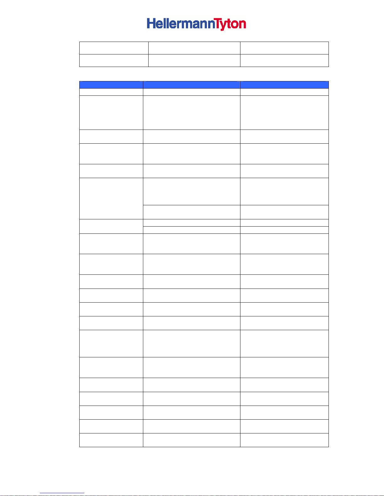
Table 7 Error Messages and Fault Corrections Part 1
Error message Cause Comment
Head open
Print head not locked Lock print head.
Head too hot
Print head is overheated After pausing the print job will
be continued automatically. If
the fault recurs repeatedly,
reduce the heat level or the
print speed via software.
Read error
Read error when reading from the
memory card
Check data of the card.
Backup data, reformat card.
Cutter jammed
The cutter is unable to cut the
labels but is able to return into its
home position
Press the cancel key. Change
material.
Card full
No more data can be stored on
the memory card.
Replace card.
Cutter cannot return into its home
position and stays in an undefined
position
Switch off the printer. Remove
material. Switch on the printer.
Restart print job. Change
material.
Cutter blocked
No cutter function Switch the printer off and then
on. If error recurs call service.
Out of label roll Load labels.
Out of paper
Error in the paper feed Check paper feed.
Protocol error
Printer has received an unknown
or invalid command from the
computer.
Press the pause key to skip the
command or press the cancel
key to cancel the print job.
Buffer overflow
The input buffer memory is full
and the computer is still
transmitting data.
Use data transmission via
protocol (preferably RTS/CTS).
Write error
Hardware error Repeat the write process,
reformat card.
Write protected
PC card write protection is
activated.
Deactivate the write protection.
Font not found
Error with the selected download
font.
Cancel current print job,
change font.
Invalid setup
Error in the configuration memory Re-configure printer. If error
recurs call service.
Voltage error
Hardware error Switch the printer off and then
on. If error recurs call service.
It is shown which voltage has
failed. Pleae note
Memory overflow
Current print job contains too
much information, e.g. selected
font, large graphics
Cancel current print job.
Reduce amount of data to be
printed.
Structural error
Error in the file list of the memory
card, data access is uncertain.
Format memory card.
Unknown card
Card not formatted. Type of card
not supported.
Format card, use different type
of card.
USB error
Device stalled
A USB device has been detected,
but it is not working
Do not use the USB device.
USB error
Too much current
The USB device consumes too
much current
Do not use the USB device.
USB error
Unknown device
Failure to detect USB device Do not use the USB device .
Table 7 Error Messages and Fault Corrections Part 2
 Loading...