

Page 1
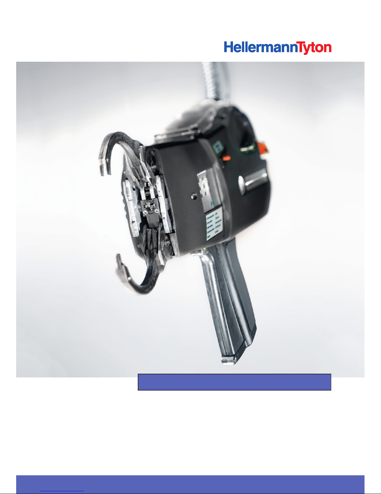
Autotool System 3080
TOC-Cover
Operating Instructions
Page 2

2
Translation of the original operating instructions 3
Page 3

Operating Instructions • ATS3080 • 02-2017 • v01 • 102-01002
3
Table of contents
1 Notes for the user . . . . . . . . . . . . . . . . . . . 5
1.1 Information about the product . . . . . . . 5
1.2 Warranty . . . . . . . . . . . . . . . . . . . . . . . . 5
1.3 Contact data . . . . . . . . . . . . . . . . . . . . . 5
1.4 Information about these Operating
Instructions . . . . . . . . . . . . . . . . . . . . . . 5
1.5 Copyright and intellectual property
rights . . . . . . . . . . . . . . . . . . . . . . . . . . . 5
1.6 Keeping and dissemination of the
Operating Instructions . . . . . . . . . . . . . . 5
1.7 Target group of these Operating
Instructions . . . . . . . . . . . . . . . . . . . . . . 5
1.8 General information . . . . . . . . . . . . . . . 5
1.9 Conventions adopted in these Operating
Instructions . . . . . . . . . . . . . . . . . . . . . . 5
1.9.1 Classification of the precautionary
notices . . . . . . . . . . . . . . . . . . . . . . . . . 5
1.9.2 Other notational conventions . . . . . . . . 6
2 Safety warnings . . . . . . . . . . . . . . . . . . . . 6
2.1 General power tool safety warnings . . . 6
2.1.1 Work area safety . . . . . . . . . . . . . . . . . . 6
2.1.2 Electrical safety . . . . . . . . . . . . . . . . . . . 6
2.1.3 Personal safety . . . . . . . . . . . . . . . . . . . 6
2.1.4 Power tool use and care . . . . . . . . . . . . 7
2.1.5 Servicing . . . . . . . . . . . . . . . . . . . . . . . . 7
2.2 Intended use . . . . . . . . . . . . . . . . . . . . . 7
2.3 Misuse. . . . . . . . . . . . . . . . . . . . . . . . . . 7
2.4 Personnel qualification . . . . . . . . . . . . . . 7
2.4.1 Specialist personnel for operation . . . . . 7
2.4.2 Specialist personnel for maintenance and
servicing . . . . . . . . . . . . . . . . . . . . . . . . 8
2.4.3 Qualified electrician . . . . . . . . . . . . . . . . 8
2.4.4 Authorised specialist for repair and
testing . . . . . . . . . . . . . . . . . . . . . . . . . . 8
2.5 Underlying hazards associated with use of
the ATS3080 . . . . . . . . . . . . . . . . . . . . . 8
2.5.1 Cleanliness at the workplace . . . . . . . . . 8
2.5.2 Spare parts and accessories . . . . . . . . . . 8
3 Design and function . . . . . . . . . . . . . . . . . 9
3.1 Scope of supply . . . . . . . . . . . . . . . . . . . 9
3.2 Functional description . . . . . . . . . . . . . 10
3.2.1 Tool ATS3080 . . . . . . . . . . . . . . . . . . . 10
3.2.2 Power pack 3080 . . . . . . . . . . . . . . . . 10
4 Transport, disposal and storage . . . . . . . 11
4.1 Transporting the device . . . . . . . . . . . . 11
4.2 Disposal . . . . . . . . . . . . . . . . . . . . . . . 11
4.3 Storage . . . . . . . . . . . . . . . . . . . . . . . . 11
4.4 Return . . . . . . . . . . . . . . . . . . . . . . . . . 11
5 Installation . . . . . . . . . . . . . . . . . . . . . . . 11
5.1 Installing the accessories . . . . . . . . . . . 11
5.2 Set limit . . . . . . . . . . . . . . . . . . . . . . . . 11
5.3 Assemble jaws . . . . . . . . . . . . . . . . . . . 12
5.4 ATS3080 connect . . . . . . . . . . . . . . . . 12
6 Operation . . . . . . . . . . . . . . . . . . . . . . . . 12
6.1 Load tie heads . . . . . . . . . . . . . . . . . . . 12
6.2 Load tie ribbon . . . . . . . . . . . . . . . . . . 12
6.3 Adjust attractive force . . . . . . . . . . . . . 13
6.4 Switching on . . . . . . . . . . . . . . . . . . . . 13
6.5 Bind . . . . . . . . . . . . . . . . . . . . . . . . . . 13
6.6 Sequence of movements in normal
operation . . . . . . . . . . . . . . . . . . . . . . 14
6.7 Positioning . . . . . . . . . . . . . . . . . . . . . 14
6.7.1 Positioning the bundle . . . . . . . . . . . . . 14
6.7.2 Geometries of bundles . . . . . . . . . . . . 14
6.8 Switching off . . . . . . . . . . . . . . . . . . . . 15
6.9 Remove tie heads . . . . . . . . . . . . . . . . 15
6.9.1 Remove the tie heads from the end cap. 15
6.9.2 Remove the tie heads from the tie head
transport. . . . . . . . . . . . . . . . . . . . . . . 15
6.10 Remove tie ribbon . . . . . . . . . . . . . . . . 15
7 Troubleshooting . . . . . . . . . . . . . . . . . . . 16
7.1 Error analysis . . . . . . . . . . . . . . . . . . . . 16
7.2 Possible faults . . . . . . . . . . . . . . . . . . . 17
7.2.1 Important notes . . . . . . . . . . . . . . . . . 18
7.2.2 Performing a reset . . . . . . . . . . . . . . . . 18
8 Maintenance . . . . . . . . . . . . . . . . . . . . . . 18
8.1 Important notes . . . . . . . . . . . . . . . . . 18
8.2 Accessories and extras . . . . . . . . . . . . . 18
8.3 Servicing by manufacturer . . . . . . . . . . 18
8.4 Maintenance schedule . . . . . . . . . . . . . 19
8.5 Repair . . . . . . . . . . . . . . . . . . . . . . . . . 19
8.5.1 Clean end cap . . . . . . . . . . . . . . . . . . . 19
8.5.2 Check jaws, upper jaw flap and lower jaw
flap . . . . . . . . . . . . . . . . . . . . . . . . . . . 19
8.5.3 Replace upper jaw flap and lower jaw
flap . . . . . . . . . . . . . . . . . . . . . . . . . . . 20
Operating Instructions
Translation of the original operating instructions
Page 4

Operating Instructions • ATS3080 • 02-2017 • v01 • 102-01002
4
8.5.4 Check and replace the ribbon knife . . . 21
9 Technical data . . . . . . . . . . . . . . . . . . . . . 22
9.1 ATS3080 . . . . . . . . . . . . . . . . . . . . . . . 22
9.1.1 Serial number . . . . . . . . . . . . . . . . . . . 23
9.1.2 Nameplate . . . . . . . . . . . . . . . . . . . . . 23
9.2 Power pack 3080 . . . . . . . . . . . . . . . . 24
9.3 Interface overview, power pack 3080 . 25
9.4 Tie heads and tie ribbons . . . . . . . . . . . 25
9.5 Noise and vibration information . . . . . . 25
10 Declarations of conformity . . . . . . . . . . . 26
10.1 ATS3080 . . . . . . . . . . . . . . . . . . . . . . . 26
10.2 Power pack 3080 . . . . . . . . . . . . . . . . 27
Page 5

Operating Instructions • ATS3080 • 02-2017 • v01 • 102-01002
Notes for the user
5
1 Notes for the user
These Operating Instructions are very important for correct
use of the ATS3080.
They contain important information and safety instructions
that will enable you to utilise the product correctly and
economically for its intended use.
The instructions help avoid hazards, reduce repair costs and
downtimes, and enhance the dependability and durability of
the ATS3080.
Non-compliance of any nature whatsoever can lead to
accidents with fatal consequences, injury or damage to
property.
1.1 Information about the product
Product designation: ATS3080
Article number: 102-00000
Further information on the product can be found on the
nameplate.
1.2 Warranty
The warranty is in accordance with statutory requirements.
Warranty entitlement applies only in the country in which
the device was originally purchased.
Batteries, fuses and light sources are not covered by the
warranty.
1.3 Contact data
The manufacturer of the product described in these
Operating Instructions is:
HellermannTyton GmbH
Grosser Moorweg 45
D-25436 Tornesch, Germany
Tel. +49 4122 701-0
www.HellermannTyton.de
1.4 Information about these Operating Instructions
Last update: 20.12.2018
1.5 Copyright and intellectual property rights
The manufacturer retains the copyright to these Operating
Instructions. Under no circumstances may these instructions
be reproduced or electronically processed, replicated or
disseminated, in whole or in part, without the prior written
consent of HellermannTyton GmbH (hereinafter referred to
as HellermannTyton). Any breach or infringement of these
stipulations will result in liability for damages.
1.6 Keeping and dissemination of the Operating
Instructions
These Operating Instructions must be kept in the immediate
vicinity of the workplace and must be available at all times to
all operating personnel. The operating company shall inform
the operating personnel of the location of these Operating
Instructions.
The operating company shall obtain replacement from the
manufacturer if these instructions are, become or are
rendered no longer easily legible.
If the ATS3080 is acquired by or sold on to a third party the
following documents must be handed over to the new
owner:
• Operating Instructions
• Documents relating to repair work
• Logs of maintenance work undertaken
f Protect these Operating Instructions from moisture,
direct sunlight and extreme heat.
1.7 Target group of these Operating Instructions
These Operating Instructions must be read and complied
with by every person charged with any of the following
tasks:
• Installation
• Operation
• Maintenance
• Repair
• Fault rectification
1.8 General information
All accompanying drawings are exempt from the
modification service.
1.9 Conventions adopted in these Operating
Instructions
1.9.1 Classification of the precautionary notices
Precautionary notices in these Operating Instructions draw
attention to hazards associated with use of the ATS3080 and
indicate how they can be avoided.
The precautionary notices are subdivided into three groups
according to the severity of the potential hazard:
DANGER
Text accompanied by the signal word "DANGER" indicate
hazardous situations which, in the event of non-compliance
with the appropriate precautions, will cause death or severe
injury.
WARNING
Text accompanied by the signal word "WARNING" indicate
hazardous situations which, in the event of non-compliance
with the appropriate precautions, can cause death or serious
injury.
Page 6

Operating Instructions • ATS3080 • 02-2017 • v01 • 102-01002
Safety warnings
6
CAUTION
Text accompanied by the signal word "CAUTION" indicate
hazardous situations which, in the event of non-compliance
with the appropriate precautions, can cause slight or serious
injury.
1.9.2 Other notational conventions
f Indicates an instruction
• Indicates an item in a bullet list
; Indicates the result of an action
This text highlight is used for names of menus, clickable
on-screen buttons, pushbuttons and switches.
This text highlight is used for display messages.
à This text highlight is used for cross-references.
NOTE
Text accompanied by the signal word "NOTE" indicate
situations which, in the event of non-compliance with the
appropriate precautions, can cause damage to the ATS3080
or the surroundings.
Text accompanied by this symbol contain useful additional
information.
2 Safety warnings
2.1 General power tool safety warnings
The safety warnings in this section contain general power
tool safety warnings to be set out in the Operating
Instructions as required by EN 62841. Consequently, some
instructions might not be relevant for the ATS3080.
WARNING
Read all safety warnings and all instructions. Failure to
follow the warning and instructions may result in electric
shock, fire and/or serious injury.
Save all safety warnings and other instructions for future
reference. The term "power tool" in the warnings refers to
your mains-operated (corded) power tool or batteryoperated (cordless) power tool.
2.1.1 Work area safety
a) Keep work area clean and well lit. Cluttered or dark
areas invite accidents.
b) Do not operate power tools in explosive
atmospheres, such as in the presence of flammable
liquids, gases or dust. Power tools create sparks which
may ignite the dust or fumes.
c) Keep children and bystanders away while operating
a power tool. Distractions can cause you to lose
control.
2.1.2 Electrical safety
a) Power tool plugs must match the outlet. Never
modify the plug in any way. Do not use any adapter
plugs with earthed (grounded) power tools.
Unmodified plugs and matching outlets will reduce risk
of electric shock.
b) Avoid body contact with earthed or grounded
surfaces, such as pipes, radiators, ranges and
refrigerators. There is an increased risk of electric shock
if your body is earthed or grounded.
c) Do not expose power tools to rain or wet conditions.
Water entering a power tool will increase the risk of
electric shock.
d) Do not abuse the cord. Never use the cord for
carrying, pulling or unplugging the power tool. Keep
cord away from heat, oil, sharp edges or moving
parts. Damaged or entangled cords increase the risk of
electric shock.
e) When operating a power tool outdoors, use an
extension cord suitable for outdoor use. Use of a cord
suitable for outdoor use reduces the risk of electric
shock.
f) If operating a power tool in a damp location is
unavoidable, use a residual current device (RCD)
protected supply. Use of an RCD reduces the risk of
electric shock.
2.1.3 Personal safety
a) Stay alert, watch what you are doing and use
common sense when operating a power tool. Do not
use a power tool while you are tired or under the
influence of drugs, alcohol or medication. A moment
of inattention while operating power tools may result in
serious personal injury.
b) Use personal protective equipment. Always wear eye
protection. Protective equipment such as a dust mask,
non-skid safety shoes, hard hat or hearing protection
used for appropriate conditions will reduce personal
injuries.
c) Prevent unintentional starting. Ensure the switch is
in the off-position before connecting to power
source and/or battery pack, picking up or carrying
the tool. Carrying power tools with your finger on the
switch or energising power tools that have the switch on
invites accidents.
d) Remove any adjusting key or wrench before turning
the power tool on. A wrench or a key left attached to
a rotating part of the power tool may result in personal
injury.
e) Do not overreach. Keep proper footing and balance
at all times. This enables better control of the power
tool in unexpected situations.
Page 7

Operating Instructions • ATS3080 • 02-2017 • v01 • 102-01002
Safety warnings
7
f) Dress properly. Do not wear loose clothing or
jewellery. Keep your hair and clothing away from
moving parts. Loose clothes, jewellery or long hair can
be caught in moving parts.
g) If devices are provided for the connection of dust
extraction and collection facilities, ensure these are
connected and properly used. Use of dust collection
can reduce dust-related hazards.
h) Do not let familiarity gained from frequent use of
tools allow you to become complacent and ignore
tool safety principles. A careless action can cause
severe injury within a fraction of a second.
2.1.4 Power tool use and care
a) Do not force the power tool. Use the correct power
tool for your application. The correct power tool will
do the job better and safer at the rate for which it was
designed.
b) Do not use the power tool if the switch does not
turn it on and off. Any power tool that cannot be
controlled with the switch is dangerous and must be
repaired.
c) Disconnect the plug from the power source and/or
remove the battery pack, if detachable, from the
power tool before making any adjustments,
changing accessories, or storing power tools. Such
preventive safety measures reduce the risk of starting the
power tool accidentally.
d) Store idle power tools out of the reach of children
and do not allow persons unfamiliar with the power
tool or these instructions to operate the power tool.
Power tools are dangerous in the hands of untrained
users.
e) Maintain power tools and accessories. Check for
misalignment or binding of moving parts, breakage
of parts and any other condition that may affect the
power tool’s operation. If damaged, have the power
tool repaired before use. Many accidents are caused
by poorly maintained power tools.
f) Keep cutting tools sharp and clean. Properly
maintained cutting tools with sharp cutting edges are
less likely to bind and are easier to control.
g) Use the power tool, accessories and tool bits etc. in
accordance with these instructions, taking into
account the working conditions and the work to be
performed. Use of the power tool for operations
different from those intended could result in a
hazardous situation.
h) Keep handles and grasping surfaces dry, clean and
free from oil and grease. Slippery handles and
grasping surfaces do not allow for safe handling and
control of the tool in unexpected situations.
2.1.5 Servicing
a) Have your power tool serviced by a qualified repair
person using only identical replacement parts. This
will ensure that the safety of the power tool is
maintained.
2.2 Intended use
Use the ATS3080 only when it is in full working order and
safe, always be safety-conscious and aware of the hazards.
The ATS3080 is suitable for and intended for the following
uses:
• Automatic binding of bundles up to a diameter of max.
80mm
• Use indoors and, under rainproof roofing, outdoors
• Industrial use
2.3 Misuse
Use other than as stated in the section entitled
"à"Intended use" on page7" is misuse. The operating
company responsible for use of the ATS3080 bears sole
responsibility for injury and damage resulting from misuse.
The following are specifically prohibited:
• Use with faulty parts
• Use in explosive environments or in the presence of a fire
hazard
• Use in high humidity and/or direct sunlight
• Simultaneous use by two or more persons
• Unauthorised alterations and modifications to the
ATS3080 and its accessories without the prior consent of
HellermannTyton
• Use of spare parts and accessories not tested and
approved beforehand by HellermannTyton
• Operation of the ATS3080 with the housing open
2.4 Personnel qualification
Underage persons and trainees are permitted to use the
device only under the supervision of an experienced
specialist and only with the express permission of the
operating company.
2.4.1 Specialist personnel for operation
The tasks and authorisations assigned to specialist personnel
for extended operation are as follows:
• Operation of the ATS3080
• Rectification of faults or, as applicable, initiation of
measures for the rectification of faults
• Cleaning of the ATS3080
These individuals have the specialist training or practical
experience that will ensure correct handling.
Page 8

Operating Instructions • ATS3080 • 02-2017 • v01 • 102-01002
Safety warnings
8
2.4.2 Specialist personnel for maintenance and
servicing
Always have maintenance and servicing carried out by duly
qualified specialist personnel. These individuals have the
specialist training that affords sucient knowledge of the
ATS3080 for them to judge when it is in safe working order.
These individuals are also familiar with the following rules
and regulations:
• Applicable national health and safety regulations
• Accident prevention regulations
• Generally accepted rules of engineering practice (e.g.
employers' liability insurance association codes, DIN
standards, VDE regulations, technical rules of other
European Union Member States or other signatories of
the Agreement on the European Economic Area).
2.4.3 Qualified electrician
Work on the electrical supply and on parts that are live when
the device is in operation should always be carried out by a
trained electrician.
2.4.4 Authorised specialist for repair and testing
Only service technicians from HellermannTyton or service
technicians certified by HellermannTyton are permitted to
carry out repairs and safety checks.
2.5 Underlying hazards associated with use of the
ATS3080
2.5.1 Cleanliness at the workplace
Orderliness, good lighting and cleanliness at the workplace
all help to make work easier, minimise hazards and reduce
the risk of injury.
Always comply with the following principles of orderliness
and cleanliness at the workplace.
f Put tools away as soon as they are no longer needed.
f Avoid trips (e.g. immediately dispose of waste by placing
it in the containers provided for the purpose).
f Immediately remove spillages of grease, oil and other
liquids.
f Clean smears off the controls.
2.5.2 Spare parts and accessories
f Use only original replacement parts.
f After parts have been replaced, always check that
everything is in full working order.
f Use only accessories approved by HellermannTyton.
Accessories can affect the way in which the ATS3080
works.
Page 9

Operating Instructions • ATS3080 • 02-2017 • v01 • 102-01002
Design and function
9
3 Design and function
3.1 Scope of supply
I
0
Power
Signal
ATS3080 Power Pack
1 2
3
10
11
12
5x
13
9
46 578
3
1 Autotool System 3080 (ATS3080)
2 Jaws diameter 30mm, diameter 50mm and diameter 80mm
3 Service box
4 Case, complete with 2 keys
5 User video DVD for the Operating instructions
6 Operating Instructions
7 Connecting cable 2m (for connecting power pack 3080 and ATS3080)
8 Power pack 3080
9 Power cable 1.8m
Contents of the service box
10 Screwdriver 2mm Allen screw
11 Screwdriver PH0 50
12 Tie head puller (5x)
13 Limit 80
For article numbers for the accessories, à"Accessories and
extras" on page18
Checking scope of supply
f Check that nothing is missing and that there are no
visible signs of damage in transit or other damage.
f Have damage confirmed by the freight forwarder and
notify HellermannTyton immediately in writing.
Page 10
Operating Instructions • ATS3080 • 02-2017 • v01 • 102-01002
Design and function
10
3.2 Functional description
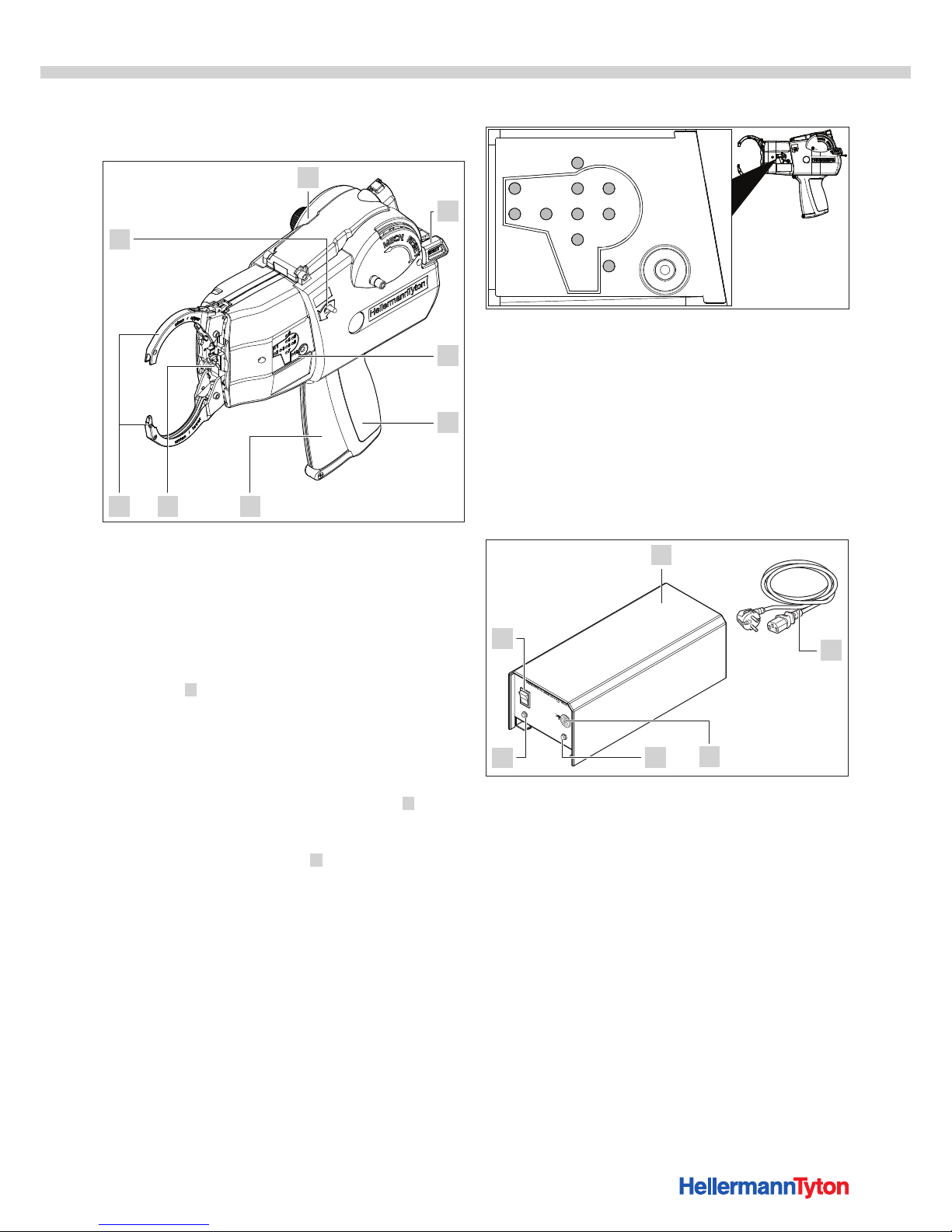
3.2.1 Tool ATS3080
567
1
3
4
2
8
1 ATS3080
2 Reset lever
3 Display
4 Grip
5 Triggering lever (trigger)
6 End cap with front sensor
7 Upper and lower jaws
8 Release lever
The ATS3080 1 is an electrically powered system for
bundling electrical wires, for example, and for securing parts
of various kinds with tie ribbon and tie heads, à"Tie heads
and tie ribbons" on page25.
The force and binding can be set on the ATS3080.
The items to be bundled have to be positioned between the
jaws and against the end cap. The triggering lever 5 is then
pressed.
If a fault occurs, the user is shown information about the
location of the fault on the display 3 and the corresponding
LED illuminates in red, à"Display" on page10
Display
1
2 3
4
5 8
6 9
10
7
1 Lock position
2 Switch
3 Start position
4 Lock material
5 Motor
6 Time
7 Overload
8 Ribbon material
9 Roller block
10 Reset
3.2.2 Power pack 3080
I
0
Power
Signal
ATS3080 Power Pack
1
4
3
2
5
6
1 Housing
2 Power cable (socket and fuse on the rear of the housing)
3 Connection for ATS3080
4 LED indicator Signal
5 LED indicator Power
6 Main switch
The power pack 3080 supplies electricity to the ATS3080. To
the interfaces on both sides of the housing, à"Interface
overview, power pack 3080" on page25.
Page 11
Operating Instructions • ATS3080 • 02-2017 • v01 • 102-01002
Transport, disposal and storage
11
4 Transport, disposal and storage
4.1 Transporting the device
f Use the supplied case for transport.
4.2 Disposal
Disposal of the ATS3080, the power pack 3080 and
individual subassemblies and the disposal of consumables
and auxiliaries are subject in part to statutory regulations.
Detailed information is available on request from the
appropriate authorities (e.g. regional or national water
boards or environmental authorities).
f Dispose of packaging materials.
Always dispose of packaging materials in accordance with
the currently valid materials-disposal and environmental
protection regulations.
f Always take materials for disposal to certified collection
points.
f Contact the manufacturer if there is any uncertainty
regarding disposal.
4.3 Storage
f ATS3080 and power pack 3080 must be stored in a cool,
dry place.
f Avoid direct sunlight.
f ATS3080 and power pack 3080 must be stored in
dustproof packaging.
f Store electrical components (ATS3080 and power pack
3080) in impact-absorbing packaging and separately
from the accessories.
f Consult and comply with the appropriate data sheets for
storage of the accessories.
4.4 Return
f Use the supplied case for returns, as otherwise you will
be invoiced for the costs of a replacement case.
5 Installation
5.1 Installing the accessories
f Always proceed in accordance with the instructions
supplied with the accessory in question.
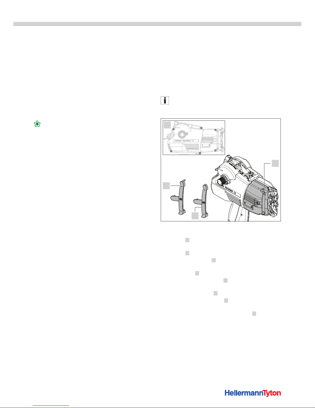
5.2 Set limit
Required tool
• Screwdriver 2.5mm Allen screw
The screwdriver 2.5mm Allen screw is not included in the
scope of supply.
Set limit
4
1
2
3
The following limits are available, à"Geometries of
bundles" on page14:
• Limit 50 4 for jaws diameter 30mm and diameter
50mm
• Limit 80 3 for jaws diameter 80mm
f Loosen the six screws 1 .
f Slightly raise the rear housing shell and remove the front
housing shell 2 .
f Turn the front housing shell 2 .
f Insert the limit suitable for the bundle into the recess of
the front housing shell 2 from the inside.
f Push the front housing shell 2 under the rear housing
shell and close the housing.
f Fasten the housing shells using the screws 1 .
Page 12
Operating Instructions • ATS3080 • 02-2017 • v01 • 102-01002
Operation
12
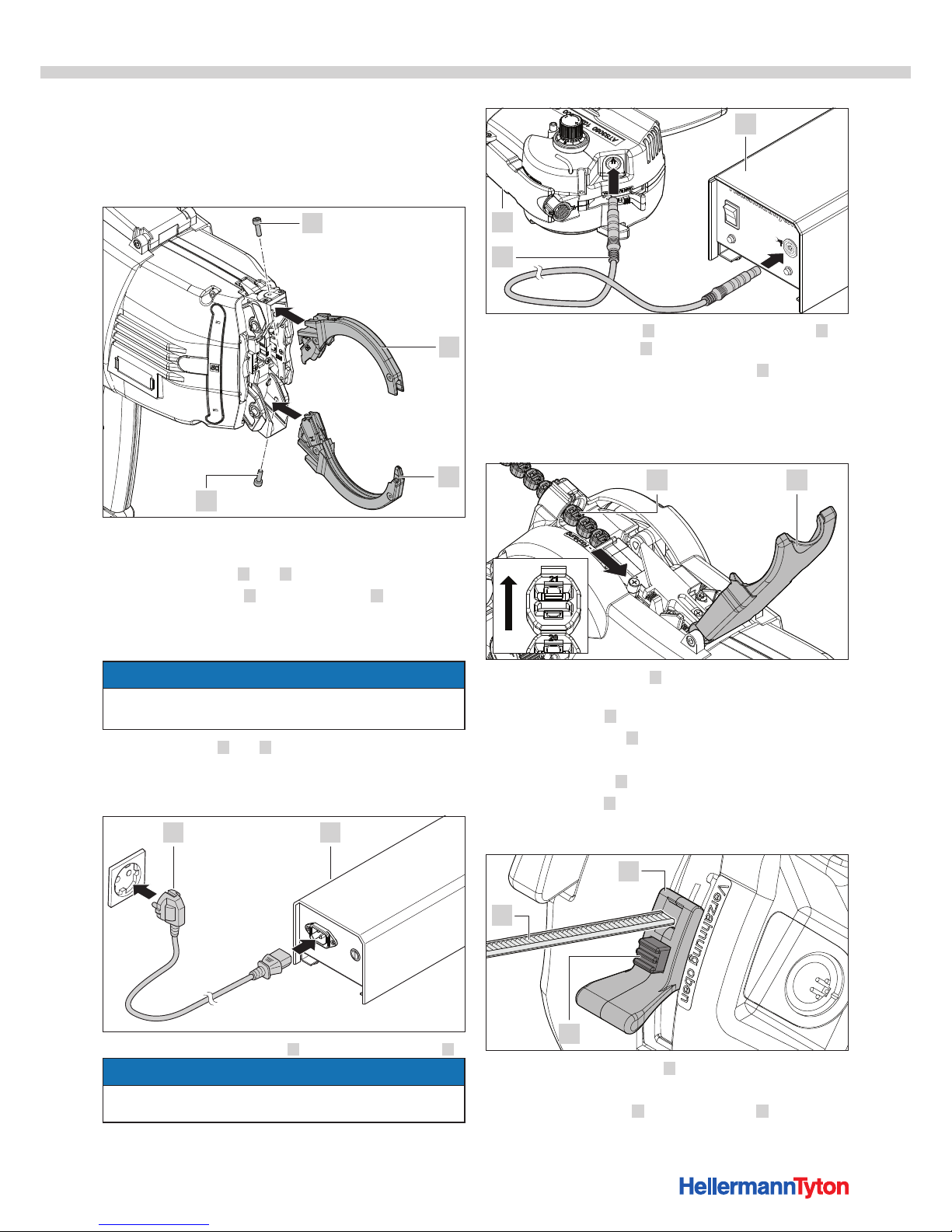
5.3 Assemble jaws
Required tool
• Screwdriver 2mm Allen screw
Assemble jaws
2
1
3
4
f Select the jaws suitable for the bundle, à"Geometries
of bundles" on page14
f Loosen the screws 1 and 4 .
f Push the upper jaw 2 and the lower jaw 3 into the
respective jaw receivers until they engage.
f Pay attention to the labelling and the correct assignment
of the upper and lower jaw.
NOTE
The screw heads do not rest on the housing.
f Do not tighten the screws up until the stop.
f Tighten screws 1 and 4 and by doing so clamp the
jaws.
5.4 ATS3080 connect
1 2
f Connect power pack 3080 2 to power-supply outlet 1 .
NOTE
The power-supply outlet must be readily accessible so that
the system can be de-energised if the need arises.
I
0
Power
Signal
ATS3080 Power Pack
2
3
1
f Connect the ATS3080 3 with the connecting cable 2 to
the power pack 3080 1 .
; The locking rings of the connecting cable 2 engage.
6 Operation
6.1 Load tie heads
21
f Insert the closure chain 1 with the number facing
towards the front and upwards.
f Open the cover 2 of the ATS3080.
f Insert closure chain 1 up to the first point.
; The LED 4 Lock material in the display goes out.
; The closure chain 1 locks firmly into place.
f Close the cover 2 .
6.2 Load tie ribbon
2
1
3
f Ensure that the tie ribbon 1 is cut at a right angle.
; The tie ribbon is at least 12cm long.
f Press the red button 3 of the roller block 2 and hold
down briefly for adjustment.
Page 13
Operating Instructions • ATS3080 • 02-2017 • v01 • 102-01002
Operation
13
f Push the roller block 2 into the central position until it
engages.
f With the teeth facing up, insert the tie ribbon 1 approx.
10cm deep.
f Slide the roller block 2 right up until the red button 3
engages.
; It must no longer be possible to pull out the tie
ribbon 1 .
; The LED 9 Roller block in the display goes out.
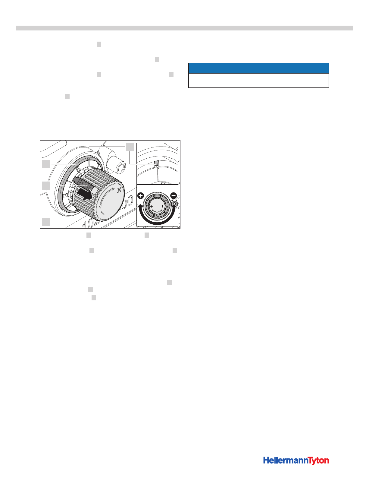
6.3 Adjust attractive force
The ATS3080 has an adjusting knob that can be used to
adjust the attractive force.
2
1
3
4
f Pull the lock pin 2 on the adjusting knob 3 out of the
gearing.
f With the lock pin 2 removed, use the adjusting knob 3
to set the desired attractive force.
• Turning clockwise will increase the attractive force.
• Turning anti-clockwise will decrease the attractive force.
; The selected setting is displayed in the white notch 4 on
the marking ring 1 .
f Allow the lock pin 2 to lock firmly into place.
6.4 Switching on
f Check the ATS3080 for readiness.
; The tie ribbon is loaded and the roller block is locked,
à"Load tie ribbon" on page12
; The tie heads are loaded in the correct direction,
à"Load tie heads" on page12
; The green field is visible on the tie head transport.
; The deflectors are extended.
If the deflectors are not extended, then a reset is
required à"Performing a reset" on page18
f Switch the power pack 3080 on at the main switch.
; The Signal and Power LEDs on the power pack3080
illuminate in green.
; The 10 Reset LED on the ATS3080 illuminates in green,
à"Display" on page10
; The ATS3080 is ready for use.
f Perform ten sample bindings.
6.5 Bind
f Guide the bundle in front of the end cap of the
ATS3080.
NOTE
f The end cap of the ATS3080 must not press against the
bundle.
f Press the triggering lever and start a binding.
; The jaws surround the bundle and the binding is carried
out.
Page 14
Operating Instructions • ATS3080 • 02-2017 • v01 • 102-01002
Operation
14
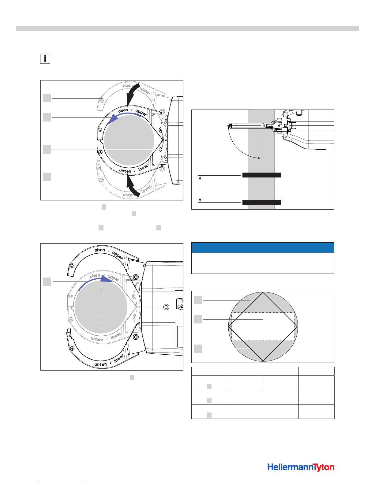
6.6 Sequence of movements in normal operation
The sequence of movements as shown here is with 50mm
jaws and a round object (bundle).
Start position
1
2
3
1
Step 1: Close the jaws 1 .
Step 2: The tie ribbon forms a loop 2 round the material.
Step 3: The ATS3080 switches to reverse.
Step 4: The deflector 3 moves back, the jaws 1 open.
Tensioning position
4
Step 5: The tie ribbon is tensioned 4 .
Step 6: The tie ribbon is cut off when the pre-set binding
strength is reached.
Step 7: The deflectors move forwards.
Step 8: The ATS3080 is ready for the next binding.
6.7 Positioning
6.7.1 Positioning the bundle
f Make sure that the bundle is always in the same
position.
f Bundle the material neatly. Make sure there are no
projecting cable-tie ends.
f Make sure that the upper and lower jaws of the
ATS3080 are not obstructed when closing.
90°
20 mm
f Guide the ATS3080 past the material to be bundled at an
angle of 90° to ensure that each binding is secure
without projecting cable-tie ends.
f Set the tie ribbons at a minimum distance of 20mm.
NOTE
In order to make a good binding, the bundle must be in a
central vertical position in relation to the jaws, à"Tensioning
position" on page14
6.7.2 Geometries of bundles
1
2
3
Dimensions Jaw 30 Jaw 50 Jaw 80
Diameter
[mm] 1
max. 30 max. 50 max. 80
Rectangle
[mm] 2
max. 12 x 27 max. 23 x 45 max. 34 x 72
Square
[mm] 3
max. 21 x 21 max. 35 x 35 max. 56 x 56
Page 15
Operating Instructions • ATS3080 • 02-2017 • v01 • 102-01002
Operation
15
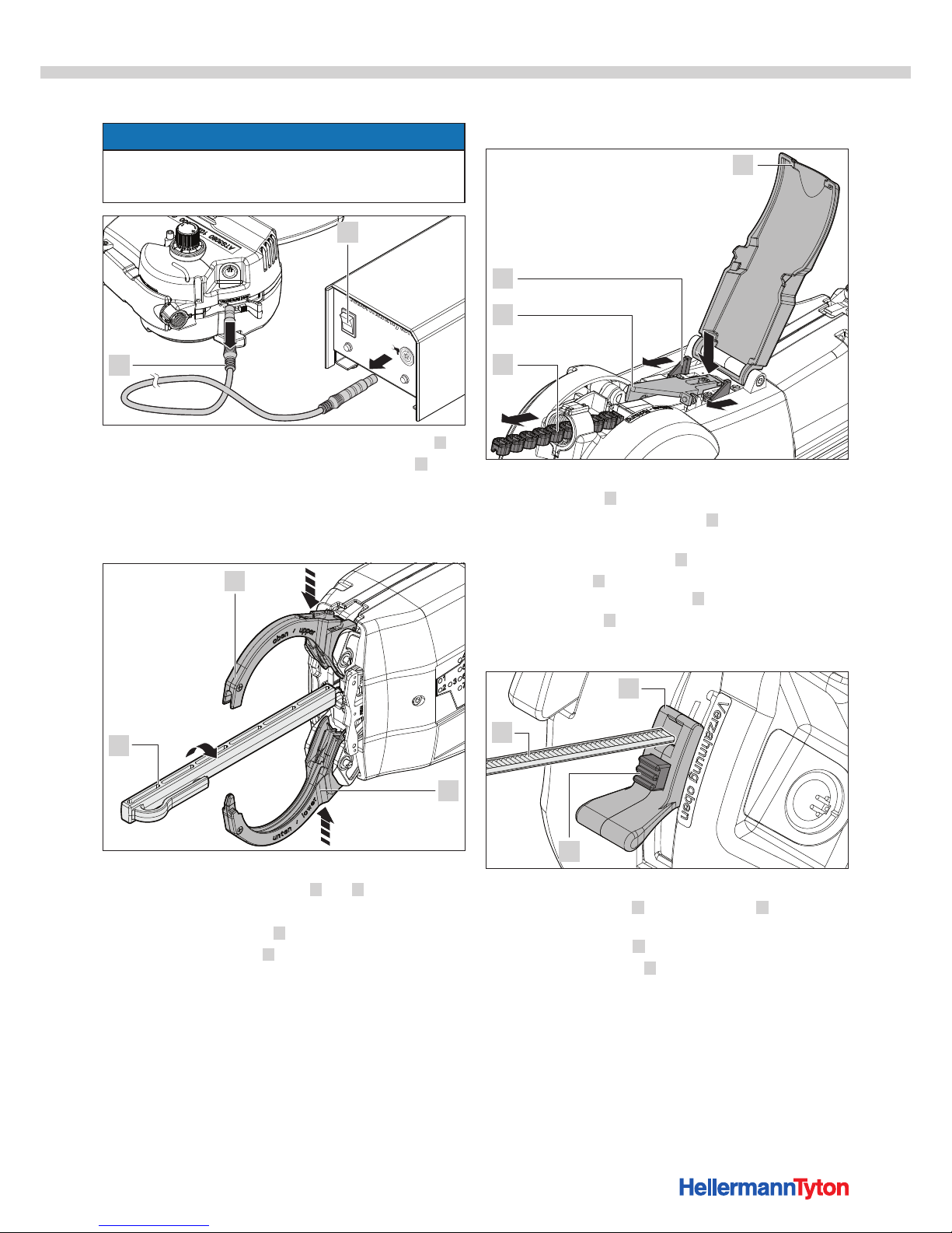
6.8 Switching off
NOTE
f Keep the main switch on the power pack 3080 off when
the ATS3080 is not in use and when a change is to be
made.
I
0
Power
Signal
ATS3080 Power Pack
2
1
f Switch the power pack 3080 off at the main switch 1 .
f Pull on the locking rings of the connecting cable 2 in
order to remove.
6.9 Remove tie heads
6.9.1 Remove the tie heads from the end cap.
1
2
3
f Switch the power pack 3080 off at the main switch.
f Lightly press together the jaws 1 and 2 .
; The tie heads are transported into the end cap.
f Insert the tie head puller 3 and turn by 90°.
f Use the tie head puller 3 to remove the tie heads.
6.9.2 Remove the tie heads from the tie head
transport.
2
3
4
1
f Switch the power pack 3080 off at the main switch.
f Open the cover 1 of the ATS3080.
f Press the tie head transport lever 3 down until the
closure chain is separated.
; The tie head transport lever 3 tilts upwards.
f Push the clips 4 backwards towards the grip, and when
doing so remove the tie heads 2 .
f Close the cover 1 .
6.10 Remove tie ribbon
2
1
3
f Switch the power pack 3080 off at the main switch.
f Press the red button 3 of the roller block 2 and hold
down.
f Push the roller block 2 into the lower position.
f Remove the tie ribbon 1 .
Page 16
Operating Instructions • ATS3080 • 02-2017 • v01 • 102-01002
Troubleshooting
16
7 Troubleshooting
7.1 Error analysis
1
2 3
4
5 8
6 9
10
7
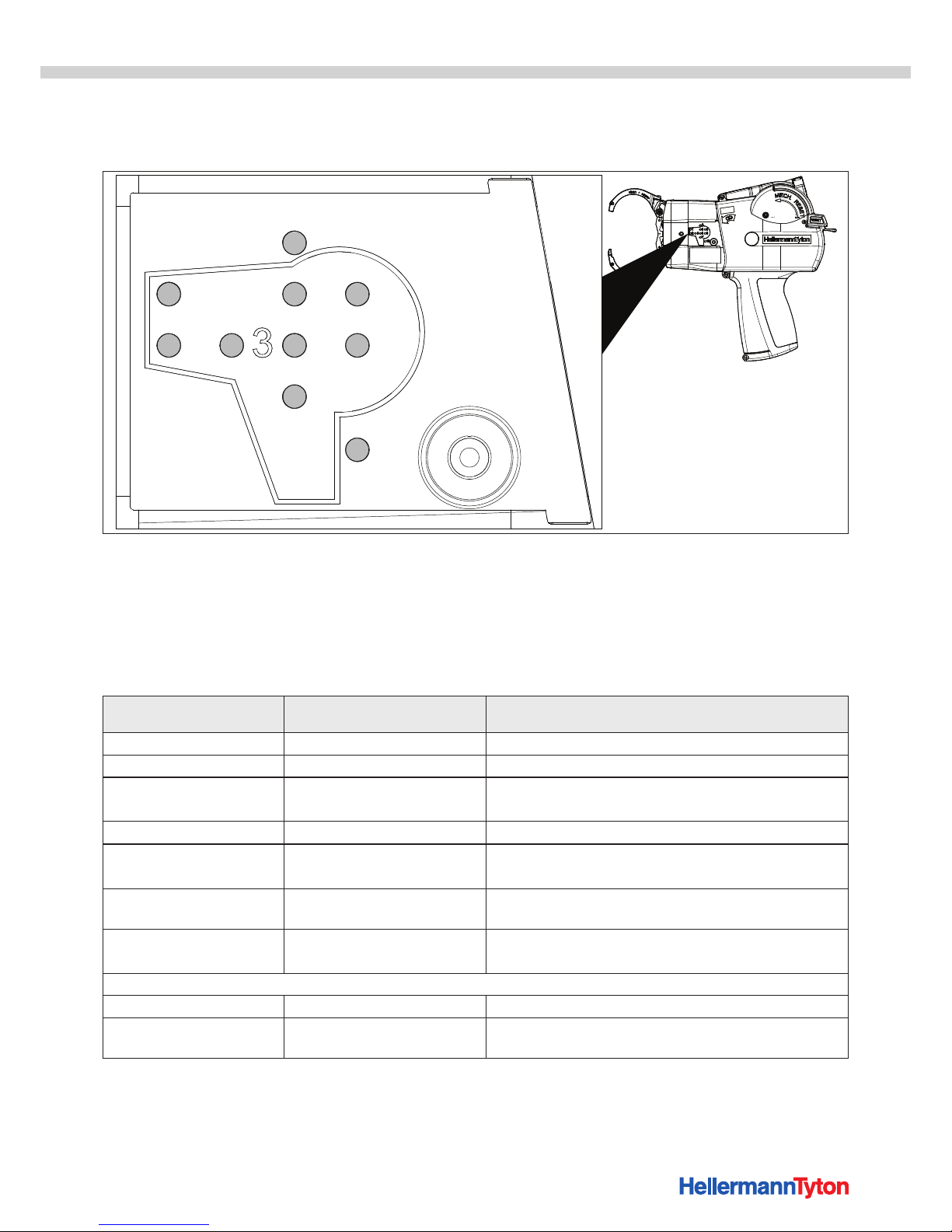
The LED lights on the display indicate the current operating
status:
• LED 10 lights up green: O.K.
• An LED lights up red: error
• No LED lights up: PCB defective
The following table describes the causes and solutions in the
event of an error notification on the display.
NOTIFICATION ON THE
DISPLAY
CAUSE FAULT RECTIFICATION
LED 1 Lock position Tie head not in position f Check end cap.
LED 2 Switch Switch lever actuated f Check end cap.
LED 3 Start position Tool not in start position f Check cycle interruption.
f Push the reset lever upwards once up to the stop.
LED 4 Lock material End of tie head chain
f Load tie heads, à"Load tie heads" on page12
LED 5 Motor Motor runs too slow
f Perform reset, à"Performing a reset" on page18
f If the reset is unsuccessful, contact service.
LED 6 Time Time limit exceeded
f Establish start position, à"Switching on" on
page13
LED 7 Overload Overload f Check blockage of the ribbon channel.
f Remove material residue in the ribbon channel.
LED 8 has no function
LED 9 Roller block Roller block open f Close the roller block.
LED 10 Reset Reset not complete
f Perform reset again, à"Performing a reset" on
page18
Page 17

Operating Instructions • ATS3080 • 02-2017 • v01 • 102-01002
Troubleshooting
17
7.2 Possible faults
The following table describes possible malfunctions on the ATS3080, for which notification is not provided on the display.
FAULT PATTERN POSSIBLE CAUSE SOLUTION
Loops form • Attractive force too low
f Adjust attractive force, à"Adjust attractive force" on
page13
Projecting cable-tie ends,
Loose binding
• Distance between bundle
and ATS3080 too large
• Bundle not aligned to be
parallel
f Move the end cap of the ATS3080 so that it is tight on
the bundle, without pressing on it.
f During the binding, the ATS3080 must not be moved
away from the material for bundling.
f Position the material for bundling, à"Positioning the
bundle" on page14
Binding not possible. Tie
ribbon shoots straight out.
• Incorrect jaw assembly
f Check jaw flap wear, à"Check jaws, upper jaw flap
and lower jaw flap" on page19
f Check jaw assembly and assemble jaws correctly,
à"Assemble jaws" on page12
The ATS3080 causes a
rasping noise.
• Incorrect jaw assembly
• Track of the jaws blocked
• Tie head chain incorrectly
inserted
f Check jaw assembly and assemble jaws correctly,
à"Assemble jaws" on page12
f Free up the jaw track.
f Cut off wear on the tie ribbon or replace tie ribbon.
f Remove tie heads and insert correctly, à"Load tie
heads" on page12
No mechanical reset
possible. The ribbon channel
is closed.
• End cap or ribbon knife
incorrectly assembled.
f Assemble end cap and ribbon knife correctly,
à"Check and replace the ribbon knife" on page21
f Free up the ribbon channel.
The jaws do not close. • Blockage caused by tie
head.
f Remove tie head from the end cap, à"Remove the tie
heads from the end cap." on page15
The tie ribbon is not cut off. • ATS3080 defective
f Send the ATS3080 to the manufacturer, à"Contact
data" on page5
The jaws spring open. • Deflector not at the front
f Perform reset, à"Performing a reset" on page18
The ATS3080 is inserted into
a device and shows an error
message on the display.
• ATS3080 incorrectly
inserted
• Device assembled
incorrectly
• ATS3080 defective
f Take the ATS3080 out of the device and carry out
binding manually.
f If the ATS3080 is in proper working order, insert it into
the device correctly or assemble the device correctly,
à"Positioning the bundle" on page14
f In the event of an unsuccessful manual function check,
send the ATS3080 to the manufacturer, à"Contact
data" on page5
Page 18
Operating Instructions • ATS3080 • 02-2017 • v01 • 102-01002
Maintenance
18
7.2.1 Important notes
CAUTION
Crush hazard when jaws close.
f Do not insert fingers between upper and lower jaws.
f Always keep the power pack 3080 switched off during
troubleshooting.
CAUTION
Crush hazard due to moving/rotating parts when
service covers are open.
f Always keep the power pack 3080 switched off during
troubleshooting.
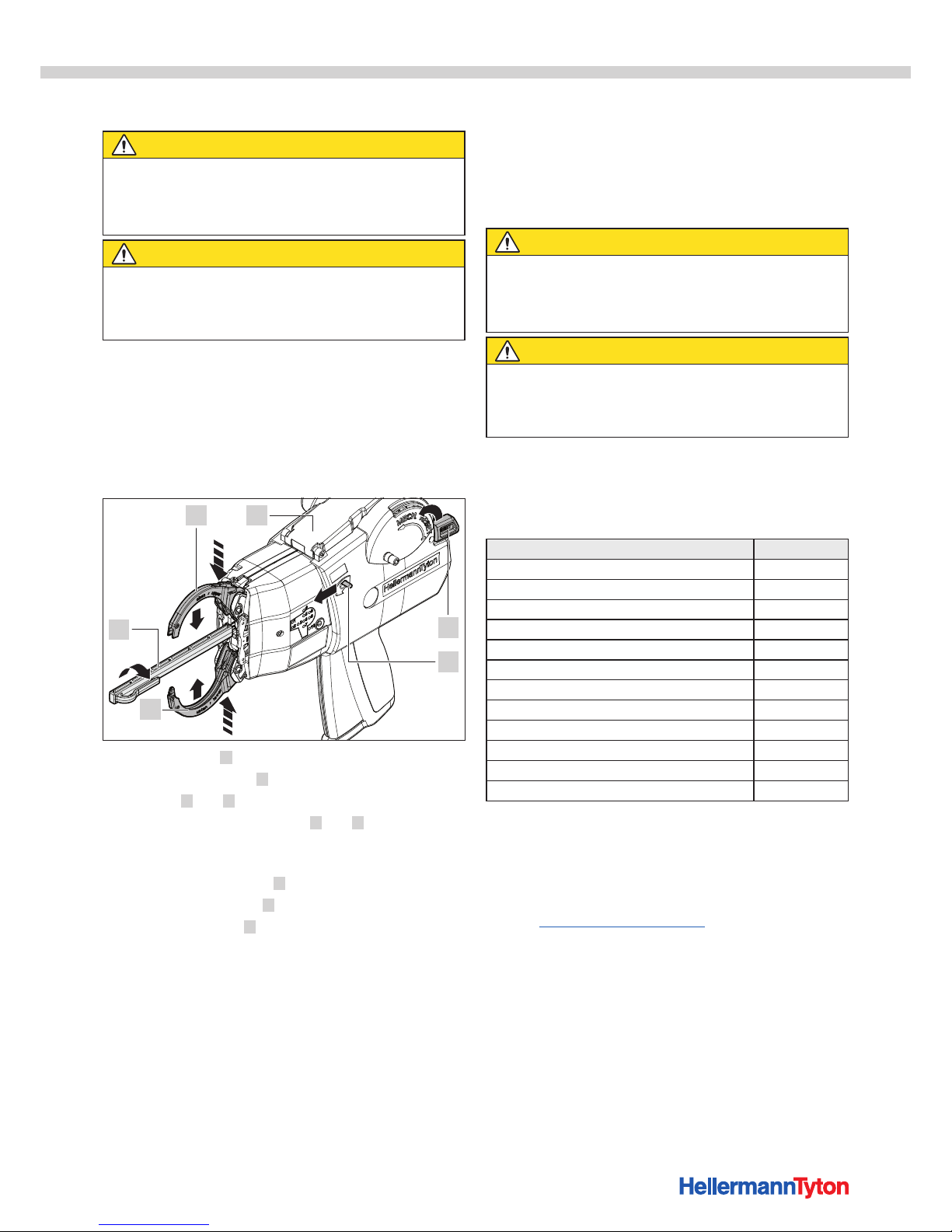
7.2.2 Performing a reset
A mechanical reset of the ATS3080 is required after a
malfunction. The electrical reset occurs automatically.
Tools needed
• Tie head puller
Performing a reset
1 2
3
4
5
6
f Close the cover 2 .
f Push the release lever 4 in the direction of the jaws.
; The jaws 1 and 5 open.
f Lightly press together the jaws 1 and 5 at the jaw
receiver (see arrows).
; The tie heads are transported into the end cap.
f Insert the tie head puller 6 and turn by 90°.
f Use the tie head puller 6 to remove a tie head.
f Push the reset lever 3 twice all the way up to the stop.
8 Maintenance
8.1 Important notes
Regular servicing is essential in order to ensure that the
ATS3080 remains in proper working order, à"Maintenance
schedule" on page19.
CAUTION
Crush hazard when jaws close.
f Do not insert fingers between upper and lower jaws.
f Always keep the power pack 3080 switched off during
maintenance work.
CAUTION
Crush hazard due to moving/rotating parts when
service covers are open.
f Always keep the power pack 3080 switched off during
maintenance work.
8.2 Accessories and extras
Accessories and extras can be ordered directly from your
national HellermannTyton representative, àseparate spare
parts list.
Name Article number
Operating Instructions 102-01002
Power pack 3080 102-00100
Power cable 1.8 m 102-00011
Connecting cable, 2 m 123-90052
Screwdriver 2mm Allen screw 102-01103
Screwdriver PH0 50 102-01105
Tie head puller 102-01110
Limit 80 102-10064
Bench mount kit movable 3080 102-00040
Bench mount kit, horizontal, 3080 102-00041
Bench mount kit automatic 3080 102-00042
Overhead suspension 3080 102-00050
8.3 Servicing by manufacturer
It is advisable to have the ATS3080 serviced by
HellermannTyton once a year or after every approx. 1 million
bindings.
Service contact addresses for all countries are posted on the
website: www.HellermannTyton.com
Page 19
Operating Instructions • ATS3080 • 02-2017 • v01 • 102-01002
Maintenance
19
8.4 Maintenance schedule
WHEN? WHO? WHAT AND HOW?
Daily Setup specialist f Blow out the end cap with compressed air.
f Check jaws for secure position.
8.5 Repair
NOTE
f Always perform a reset before commencing repair work,
à"Performing a reset" on page18.
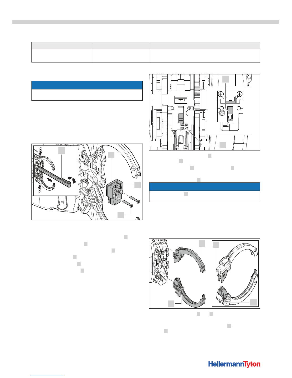
8.5.1 Clean end cap
Required tool
• Tie head puller
• Screwdriver PH0 50
Clean end cap
1
2
3
4
f Lightly press together the jaws at the jaw receiver (see
arrows).
; The tie heads are transported into the end cap 2 .
f Insert the tie head puller 4 and turn by 90°.
f Remove the tie heads from the end cap 2 .
f Loosen the screws 3 of the end cap.
f Remove the end cap 2 .
f Dismantle the end cap 2 and clean with compressed air
or a brush, à"Check and replace the ribbon knife" on
page21
f Blow the front area of the ATS3080 with compressed air.
5
6
f Ensure that the ribbon knife 5 and the levers of the
ribbon knife 6 are in the open position (down).
f Insert the end cap 2 and use the screws 3 to secure.
f Ensure that you do not cause any damage when
inserting the two pins 1 in the end area.
NOTE
Damage to the pins 1 will cause the ATS3080 to
malfunction.
8.5.2 Check jaws, upper jaw flap and lower jaw flap
Required tool
• Screwdriver 2mm Allen screw
Check jaws, upper jaw flap and lower jaw flap
2
3
4
1
f Remove the two jaws 1 and 4 from the ATS3080 ,
à"Assemble jaws" on page12
f Check the jaws and the upper jaw flap 2 and lower jaw
flap 3 for wear or chipping.
f In the event of wear or chipping, insert new jaws.
Page 20
Operating Instructions • ATS3080 • 02-2017 • v01 • 102-01002
Maintenance
20
f In the event of wear or chipping, replace the upper jaw
flap 2 and the lower jaw flap 3 , à"Replace upper jaw
flap and lower jaw flap" on page20
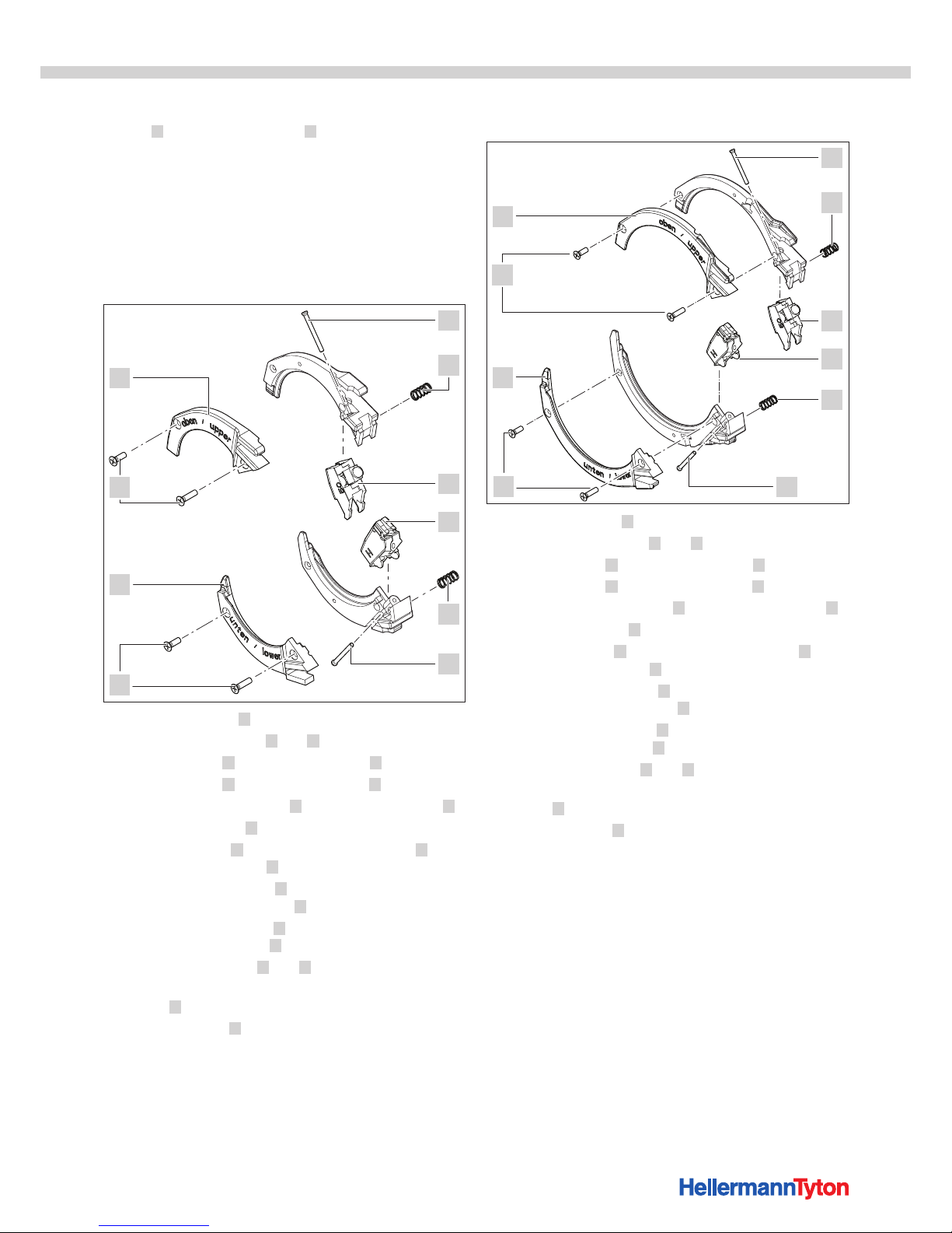
8.5.3 Replace upper jaw flap and lower jaw flap
Required tools and resources
• Screwdriver PH0 50
• Loctite 243 (optionally available from HellermannTyton)
Replace lower jaw flap and upper jaw flap of
jawdiameter 30
7
8
5
2
4
3
1
2
6
6
f Loosen the screws 6 on the upper and lower jaw.
f Remove the jaw halves 7 and 8 .
f Remove the pin 1 on the upper jaw flap 3 .
f Remove the pin 5 on the lower jaw flap 4 .
f Remove the upper jaw flap 3 and the lower jaw flap 4 .
f Remove the springs 2 .
f Insert the springs 2 into the new upper jaw flap 3 and
the new lower jaw flap 4 .
f Insert the upper jaw flap 3 into the upper half of the
jaw and secure with the pin 1 .
f Insert the lower jaw flap 4 into the lower half of the jaw
and secure with the pin 5 .
f Attach the jaw halves 7 and 8 .
f Apply a drop of Loctite 243 to the thread of each of the
screws 6 .
f Insert the screws 6 and tighten.
Replace lower jaw flap and upper jaw flap of
jawdiameter 50
7
8
5
2
4
3
1
2
6
6
f Loosen the screws 6 on the upper and lower jaw.
f Remove the jaw halves 7 and 8 .
f Remove the pin 1 on the upper jaw flap 3 .
f Remove the pin 5 on the lower jaw flap 4 .
f Remove the upper jaw flap 3 and the lower jaw flap 4 .
f Remove the springs 2 .
f Insert the springs 2 into the new upper jaw flap 3 and
the new lower jaw flap 4 .
f Insert the upper jaw flap 3 into the upper half of the
jaw and secure with the pin 1 .
f Insert the lower jaw flap 4 into the lower half of the jaw
and secure with the pin 5 .
f Attach the jaw halves 7 and 8 .
f Apply a drop of Loctite 243 to the thread of each of the
screws 6 .
f Insert the screws 6 and tighten.
Page 21
Operating Instructions • ATS3080 • 02-2017 • v01 • 102-01002
Maintenance
21
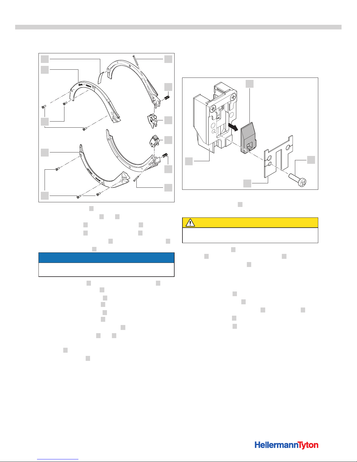
Replace lower jaw flap and upper jaw flap of
jawdiameter 80
7
8
9
5
2
4
3
1
2
6
6
f Loosen the screws 6 on the upper and lower jaw.
f Remove the jaw halves 7 and 8 .
f Remove the pin 1 on the upper jaw flap 3 .
f Remove the pin 5 on the lower jaw flap 4 .
f Remove the upper jaw flap 3 and the lower jaw flap 4 .
f Remove the springs 2 .
NOTE
The flaps in the diameter 80 jaw are different from the flaps
in the diameter 30 and diameter 50 jaws.
f Insert the springs 2 into the new upper jaw flap 3 and
the new lower jaw flap 4 .
f Insert the upper jaw flap 3 into the upper half of the jaw
and secure with the pin 1 .
f Insert the lower jaw flap 4 into the lower half of the jaw
and secure with the pin 5 .
f Insert the sheet metal part QZ80 9 .
f Attach the jaw halves 7 and 8 .
f Apply a drop of Loctite 243 to the thread of each of the
screws 6 .
f Insert the screws 6 and tighten.
8.5.4 Check and replace the ribbon knife
Required tool
• Screwdriver PH0 50
Check and replace the ribbon knife
1
2
4
3
f Dismantle the jaws, à"Assemble jaws" on page12
f Remove the end cap 4 , à"Clean end cap" on
page19
CAUTION
Cut hazard. The ribbon knife is extremely sharp.
f Never touch the cutting edge with your fingers.
f Loosen the screw 2 and remove with the end cap
cover 3 from the reverse of the end cap 4 .
f Remove the ribbon knife 1 and clean with compressed
air.
f Check the ribbon knife for damage and replace if
necessary.
f Clean the end cap 4 with compressed air.
f Insert the ribbon knife 1 with positive locking.
f Insert the cover of the end cap 3 with the screw 2 .
f Tighten the screw 2 .
f Insert the end cap 4 , à"Clean end cap" on page19.
Page 22
Operating Instructions • ATS3080 • 02-2017 • v01 • 102-01002
Technical data
22
9 Technical data
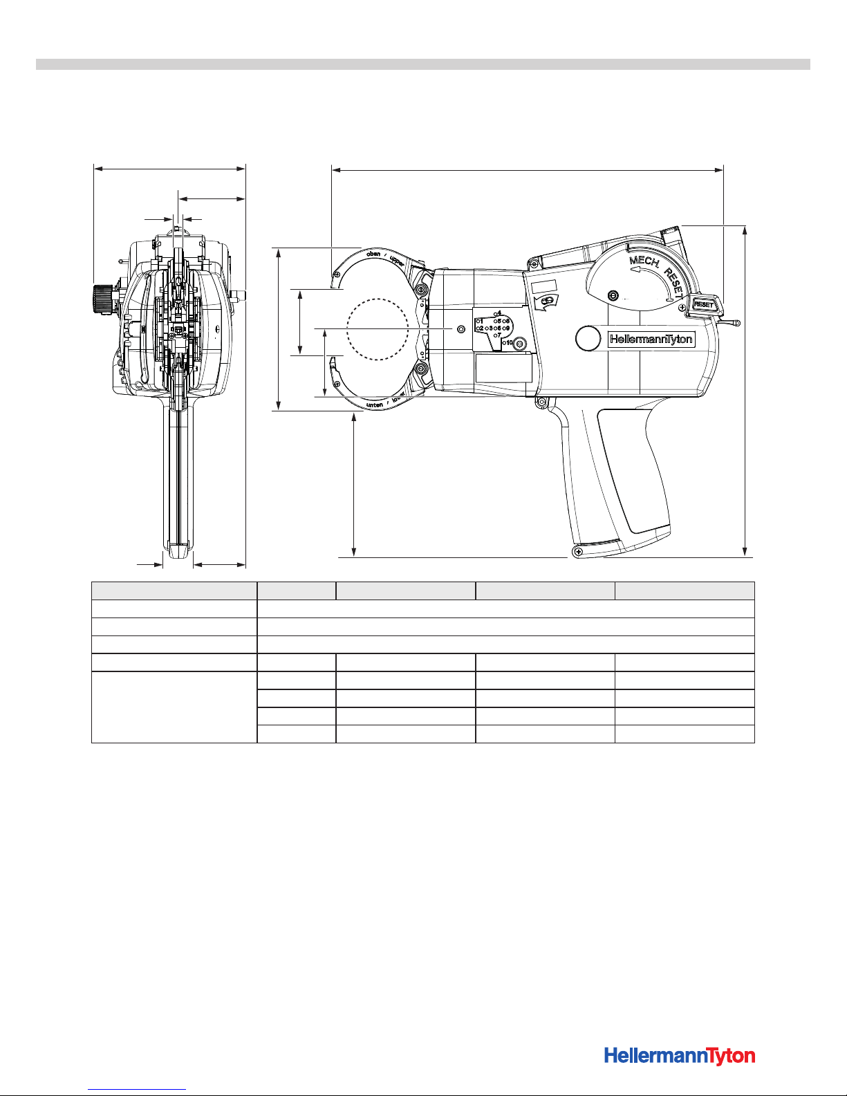
9.1 ATS3080
248
121
b
c
e
113,8
a
50,1
39
22
7,8
Ø d
Value Jaws diameter 30mm Jaws diameter 50mm Jaws diameter 80mm
Max. power draw 60 W
Input voltage 48 V
Weight approx. 1900 g
Bundle thickness diameter d 30 mm 50 mm 80 mm
Dimensions a 272 mm 293 mm 329 mm
b Max. 111 mm Max. 134 mm Max. 175 mm
c Max. 64 mm Max. 68 mm Max. 80 mm
e Max. 50 mm Max. 50 mm Max. 50 mm
Page 23
Operating Instructions • ATS3080 • 02-2017 • v01 • 102-01002
Technical data
23
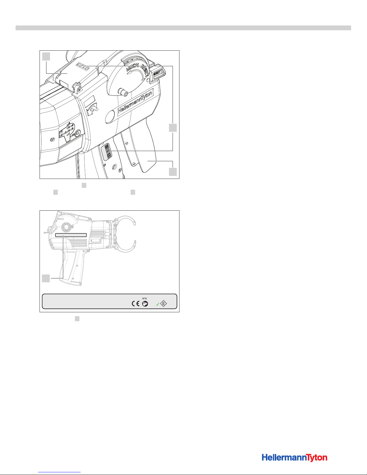
9.1.1 Serial number
0123
2
3
1
The serial number 2 of the ATS3080 is under the grip
cover 3 and on the inside of the cover 1 .
9.1.2 Nameplate
HellermannTyton
Autotool System 3080
102-00900
HellermannTyton GmbH
Großer Moorweg 45, 25438 Tornesch
Tel. +49 4122 701-0 . Fax +49 4122 701-344
E-Mail: [email protected]
www.HellermannTyton.de
Made in Germany
Input: 48V max. 60W
Year 2017
RoHS
1
The nameplate 1 is on the right side of the housing.
Page 24
Operating Instructions • ATS3080 • 02-2017 • v01 • 102-01002
Technical data
24
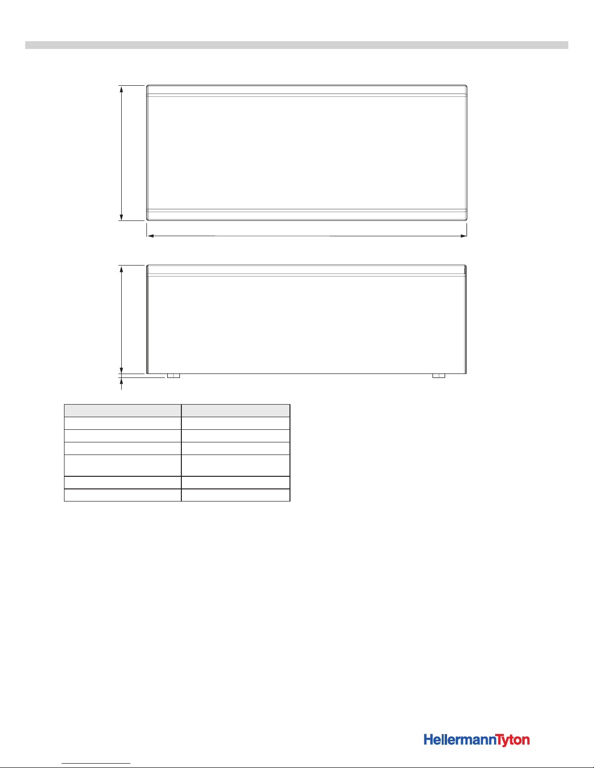
9.2 Power pack 3080
110
258
933,3
Value
Line voltage 100 V – 230 V
Line frequency 50/60 Hz
Protection class I
Dimensions L × W × H approx. 260 mm × 110 mm × 93
mm
Weight approx. 1500 g
Connecting cable and plug Certified as per UL 1977
Page 25
Operating Instructions • ATS3080 • 02-2017 • v01 • 102-01002
Technical data
25
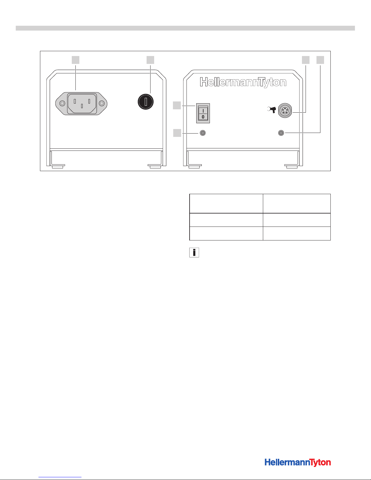
9.3 Interface overview, power pack 3080
SignalPower
ATS3080 Power Pack
6
1 2 3 4
5
1 Socket for power cable
2 Fuse
3 Socket for connection to ATS3080 or to the control boxes
4 Signal LED
Green: Operating voltage applied
5 LED indicator Power
Green: power pack 3080 switched on
6 Main switch
9.4 Tie heads and tie ribbons
• Tie ribbon (500m × 4.5mm × 1.2mm (L × W × H)) of
type PA66HIRHSUV
• Tie heads (5000 items, each 9.0 mm × 8.0 mm × 5.4 mm
(L × W × H)) of type PA66HSUV
9.5 Noise and vibration information
Emission sound pressure level
L
pA
Uncertainty K
pA
71 dB re20 μPa
3 dB
Sound power level L
WA
Uncertainty K
WA
82 dB re1pW
3 dB
Aggregate figure for vibration a
h
Uncertainty K
1.0 m/s
2
1.5 m/s
2
The vibration level as stated here is a measured value
obtained by the standardised method set out in EN 628411:2015; it can be used for the purposes of device
comparison.
The figure for vibration stated here is for the power tool in
conditions of its intended use and may differ from the actual
figure for the power tool if it is used differently or not
adequately serviced.
Accurately estimating vibration load over a certain work
period entails making due allowance for the times during
which the device is switched off or running, but not actually
in use. This can reduce vibration load over the entire work
period by a significant margin.
f Implement additional safety measures to protect the
operator from the effects of vibration, for example:
• Servicing of power tools and use tools
• Keeping hands warm
• Workflow organisation.
Page 26
Operating Instructions • ATS3080 • 02-2017 • v01 • 102-01002
Declarations of conformity
26
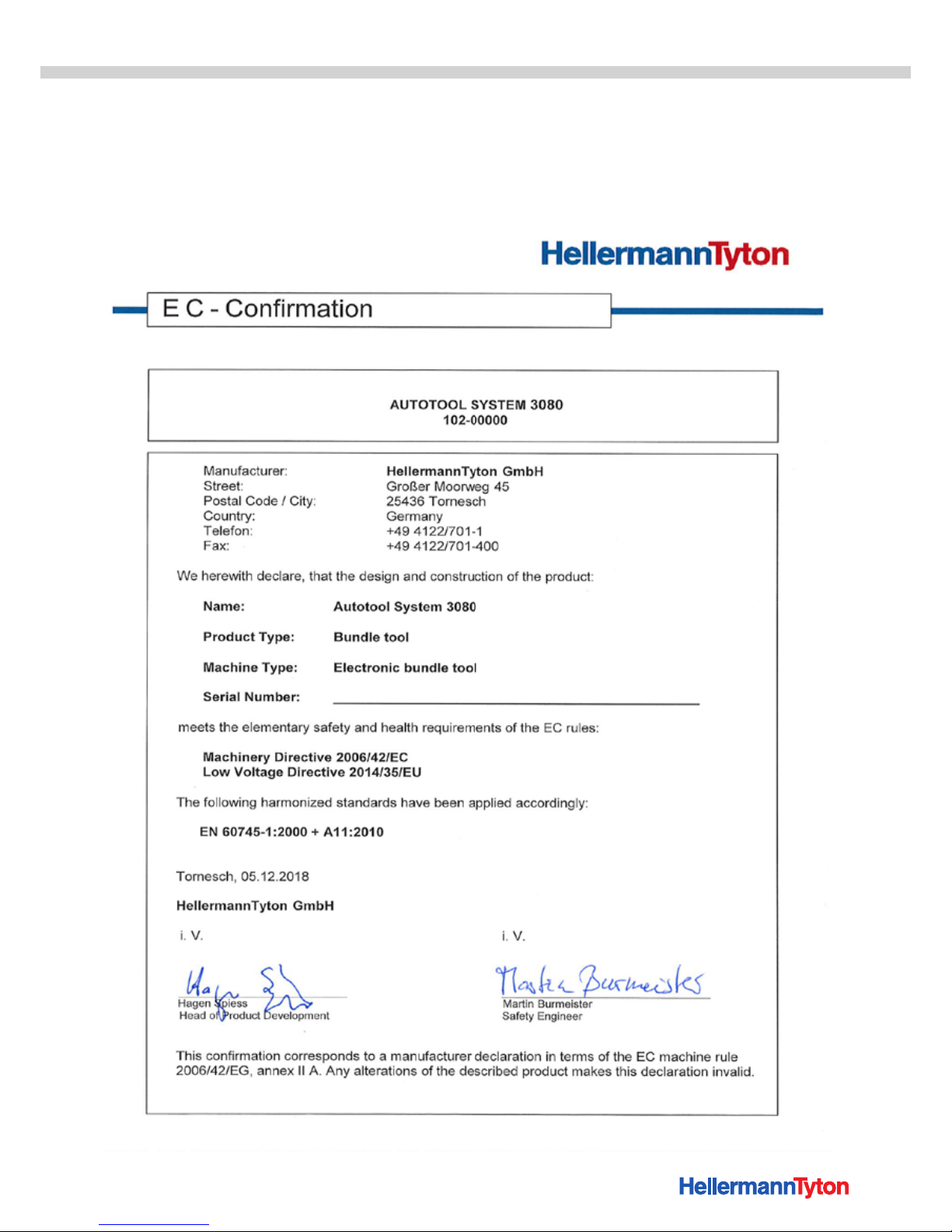
10 Declarations of conformity
10.1 ATS3080
Page 27
Operating Instructions • ATS3080 • 02-2017 • v01 • 102-01002
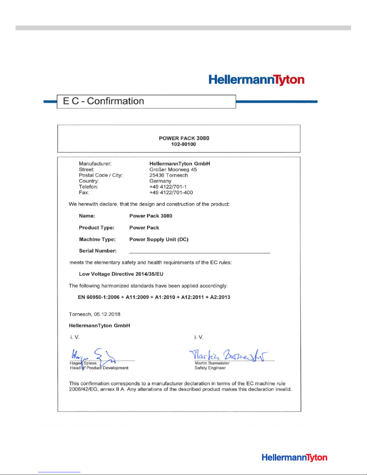
Declarations of conformity
27
10.2 Power pack 3080
Page 28

Europe
HellermannTyton GmbH – Austria
Rennbahnweg 65
1220 Vienna
Tel.: +43 12 59 99 55-0
Fax: +43 12 59 99 11
Email: o [email protected]
www.HellermannTyton.at
HellermannTyton – Bulgaria
Email: o [email protected]
www.HellermannTyton.at
HellermannTyton – Czech Republic
Email: o [email protected]
www.HellermannTyton.cz
HellermannTyton – Denmark
Industrivej 44A, 1.
4000 Roskilde
Tel.: +45 702 371 20
Fax: +45 702 371 21
Email: [email protected]
www.HellermannTyton.dk
HellermannTyton – Finland
Äyritie 12 B
01510 Vantaa
Tel.: +358 9 8700 450
Fax: +358 9 8700 4520
Email: myynti@HellermannTyton.fi
www.HellermannTyton.fi
HellermannTyton S.A.S. – France
2 rue des Hêtres - CS 80543
78197 Trappes Cedex
Tel.: +33 1 30 13 80 00
Fax: +33 1 30 13 80 60
Email: [email protected]
www.HellermannTyton.fr
HellermannTyton GmbH – Germany
Großer Moorweg 45
25436 Tornesch
Tel.: +49 4122 701-0
Fax: +49 4122 701-400
Email: [email protected]
www.HellermannTyton.de
HellermannTyton KFT – Hungary
Kisfaludy u. 13
1044 Budapest
Tel.: +36 1 369 4151
Fax: +36 1 369 4151
Email: o [email protected]
www.HellermannTyton.hu
HellermannTyton Ltd – Ireland
Unit A5 Cherry Orchard
Business Park
Ballyfermot, Dublin 10
Tel.: +353 1 626 8267
Fax: +353 1 626 8022
Email: [email protected]
www.HellermannTyton.co.uk
HellermannTyton S.r.l. – Italy
Via Visco, 3/5
35010 Limena (PD)
Tel.: +39 049 767 870
Fax: +39 049 767 985
Email: [email protected]
www.HellermannTyton.it
HellermannTyton B.V. –
Belgium/Netherlands
Vanadiumweg 11-C
3812 PX Amersfoort
Tel.: +31 33 460 06 90
Fax: +31 33 460 06 99
Email (NL): [email protected]
Email (BE): [email protected]
www.HellermannTyton.nl
www.HellermannTyton.be
HellermannTyton AS – Norway
Nils Hansens vei 13
0667 Oslo
Tel.: +47 23 17 47 00
Fax: +47 22 97 09 70
Email: fi [email protected]
www.HellermannTyton.no
HellermannTyton Sp. z o.o. – Poland
Kotunia 111
62-400 Słupca
Tel.: +48 63 2237 111
Fax: +48 63 2237 110
Email: [email protected]
www.HellermannTyton.pl
HellermannTyton – Romania
Email: o [email protected]
www.HellermannTyton.at
OOO HellermannTyton – Russia
40/4, Pulkovskoe road
BC Technopolis Pulkovo, o ce A 8081
196158, St. Petersburg
Tel.: +7 812 386 00 09
Fax: +7 812 386 00 08
Email: [email protected]
www.Hellermanntyton.ru
HellermannTyton – Slovenia
Branch O ce Ljubljana
Podružnica Ljubljana, Ukmarjeva 2
1000 Ljubljana
Tel.: +386 1 433 70 56
Fax: +386 1 433 63 21
Email: o [email protected]
www.HellermannTyton.si
HellermannTyton España s.l. –
Spain / Portugal
Avda. de la Industria 37 2° 2
28108 Alcobendas, Madrid
Tel.: +34 91 661 2835
Fax: +34 91 661 2368
Email:
[email protected]
www.HellermannTyton.es
HellermannTyton AB – Sweden
Isafjordsgatan 5
16440 Kista
Tel.: +46 8 580 890 00
Fax: +46 8 580 348 02
Email: [email protected]
www.HellermannTyton.se
HellermannTyton
Engineering GmbH – Turkey
Saray Mah Dr. Adnan Büyükdeniz Cad. No:4
Akkom O ce Park 2. Blok Kat: 10
34768 Ümraniye-İstanbul
Tel.: +90 216 687 03 40
Fax: +90 216 250 32 32
Email: [email protected]
www.HellermannTyton.com.tr
HellermannTyton Ltd – UK
William Prance Road
Plymouth International Medical
and Technology Park
Plymouth, Devon PL6 5WR
Tel.: +44 1752 701 261
Fax: +44 1752 790 058
Email: [email protected]
www.HellermannTyton.co.uk
HellermannTyton Ltd – UK
Sharston Green Business Park
1 Robeson Way
Altrincham Road, Wythenshawe
Manchester M22 4TY
Tel.: +44 161 947 2200
Fax: +44 161 947 2220
Email: [email protected]
www.HellermannTyton.co.uk
HellermannTyton Ltd – UK
Cley Road, Kingswood Lakeside
Cannock, Staffordshire
WS11 8AA
Tel.: +44 1543 728282
Fax: +44 1543 728284
Email: [email protected]
www.HellermannTyton.co.uk
HellermannTyton Data Ltd – UK
Waterside House, Edgar Mobbs Way
Northampton NN5 5JE
Tel.: +44 1604 707 420
Fax: +44 1604 705 454
Email: [email protected]
www.htdata.co.uk
Middle East
HellermannTyton – UAE
Email: [email protected]
www.HellermannTyton.ae
North America
HellermannTyton – Canada
Tel.: +1 905 726 1221
Fax: +1 905 726 8538
Email: [email protected]
www.HellermannTyton.ca
HellermannTyton – Mexico
Tel.: +52 333 133 9880
Fax: +52 333 133 9861
Email: [email protected]
www.HellermannTyton.com
HellermannTyton – USA
Tel.: +1 414 355 1130
Fax: +1 414 355 7341
Email: [email protected]
www.HellermannTyton.com
South America
HellermannTyton – Argentina
Tel.: +54 11 4754 5400
Fax: +54 11 4752 0374
Email: [email protected]
www.HellermannTyton.com.ar
HellermannTyton – Brazil
Tel.: +55 11 4815 9000
Fax: +55 11 4815 9030
Email: [email protected]
www.HellermannTyton.com.br
Asia-Pacifi c
HellermannTyton – Australia
Tel.: +61 2 9525 2133
Fax: +61 2 9526 2495
Email: [email protected]
www.HellermannTyton.com.au
HellermannTyton – China
Tel.: +86 510 8528 2536
Fax: +86 510 8528 2731
Email: [email protected]
www.HellermannTyton.com.cn
HellermannTyton – Hong Kong
Tel.: +852 2831 9090
Fax: +852 2832 9381
Email: [email protected]
www.HellermannTyton.com.sg
HellermannTyton – India
Tel.: +91 120 413 3384
Email: [email protected]
www.HellermannTyton.co.in
HellermannTyton – Japan
Tel.: +81 3 5790 3111
Fax: +81 3 5790 3112
Email: [email protected]
www.HellermannTyton.co.jp
HellermannTyton – Republic of Korea
Tel.: +82 32 833 8012
Fax: +82 32 833 8013
Email: [email protected]
www.HellermannTyton.co.kr
HellermannTyton – Philippines
Tel.: +63 2 752 6551
Fax: +63 2 752 6553
Email: [email protected]
www.HellermannTyton.com.ph
HellermannTyton – Singapore
Tel.: +65 6 586 1919
Fax: +65 6 752 2527
Email: [email protected]
www.HellermannTyton.com.sg
HellermannTyton – Thailand
Tel.: +662 237 6702 / 266 0624
Fax: +662 266 8664
Email: [email protected]
www.HellermannTyton.com.sg
Africa
HellermannTyton – South Africa
Tel.: +27 11 879 6600
Fax: +27 11 879 6603
Email: [email protected]
www.HellermannTyton.co.za
106-29010 / 106-2901102-2017
HellermannTyton operates globally in 37 countries
 Loading...