

Page 1
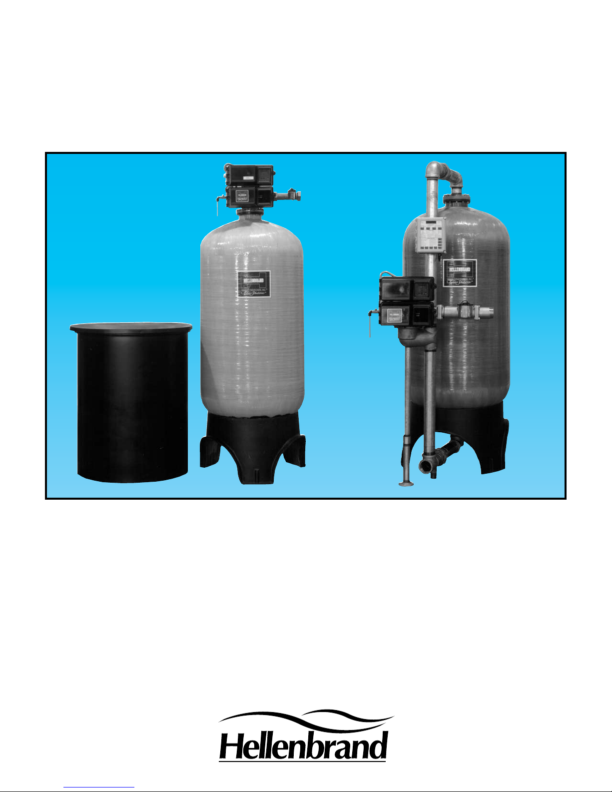
TNT SERIES
WATER CONDITIONERS
For Commercial & Industrial Applications
Apartment Buildings
Boiler Water Treatment
Car Washes
Commercial Buildings
Condominiums
Factories
Hospitals
Laundries
Mobile Home Parks
Motels and Hotels
Nursing and Rest Homes
Ofce Buildings
Restaurants
Schools
Page 2
Hellenbrand Means
Quality and Reliability
Since 1967, Hellenbrand Water Conditioners, Inc. has provided water solutions to the water treatment industry in the
U.S. and around the world. We have developed a complete line of high quality products. An excellent example of this,
is the Hellenbrand TNT Series Conditioners.
TNT Series Conditioners use a anged top-mounted or optional side-mounted adapter, three-inch NPT inlet and outlet
solid brass control valve with a motor-driven, time-tested, hydraulically-balanced piston with a seal and spacer concept
to pilot service ow not dependent on water pressure. No diaphragms to rupture or false transfer. It will provide up to
170 gpm hard water by-pass during regeneration, or you may have the optional “no hard water by-pass piston” for twin
or multiple systems. These high service ow rates, the simplied alternating and multiple lockout systems, eliminate the
need for diaphragms, solenoids and stagers. The ve cycle TNT controller is available with either downow (co-current)
or upow (counter-current) brining, with easy adjustable cycle times. The TNT Series offers you a choice of mechanical
or microprocessor controlled meter demand systems, with two-inch or three-inch meter turbines. All systems are factory-wired and tested electrically to assure easy installation and correct operation.
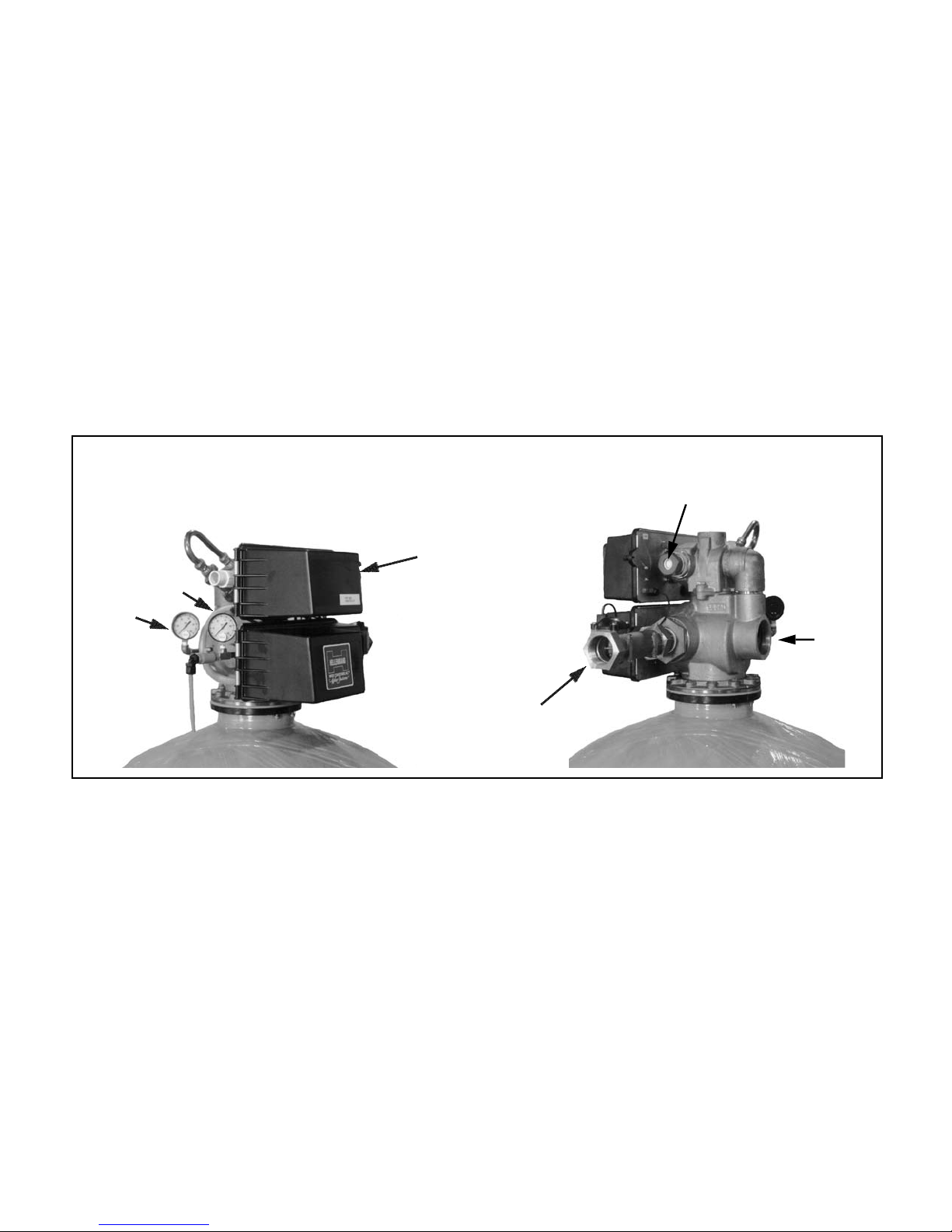
FRONT VIEW
Optional Inlet & Outlet Pressure Gauges & Soft Water
Test Port
Controller
Outlet
Inlet
Optional Factory Installed Vacuum
Breaker
Optional
2” Meter Outlet
BACK VIEW
TNT Series Control Valve -Three Inch Inlet/Outlet
1. Stainless Steel Backplate will not rust or corrode.
2. Factory provided Drain Line Flow Control maintains
accurate backwash rates.
3. Three-Inch NPT Inlet & Outlet Connections.
4. Solid Brass Valve assures durability and long life.
5. Hydraulically-balanced Piston, Seal, and Spacers.
Lower service piston is available with or without hard
water by-pass. Non-sticking Teon-coated Piston al-
lows foreign particles to pass through without damaging
the unit.
6. Upper Piston pilots the regeneration steps of backwash,
brine and slow rinse, fast rinse, and brine tank rell.
7. Separate “Time-ll” Brining with accurate ow controls
allows automatic brine tank rell. Brine Tank Rell
Rates are easily adjustable on the cycle programmer. No need to worry about adjusting oat valves or
repositioning brine plugs for salt measurements.
8. Heavy-duty Drive Motor receives signal from timer
to efciently direct water ow during regeneration.
Piston shifts smoothly and quietly regardless of water
pressure.
9. Lower Heavy-duty Drive Motor receives signal from
upper drive motor to direct the service piston into position. Piston shifts smoothly and quietly regardless of
water pressure.
10. TNT Series Timer provides fully automatic, dependable timing for regeneration. The Cycle Programmer
regulates all regeneration cycles which are easily
adjustable. For manual regeneration start, simply turn
the service indicator clockwise.
Inlet
Page 3
TN2 Standard System Design Options
(for more specic information on the various system designs, contact your local Hellenbrand representative or go to: www.hellenbrand.com
1. Single Tank Systems - XT Controller
• Time Clock
• XT Controller Electronic Meter Demand
Twin, Tri-Plex & Four-Plex Systems - 3200NXT Controller
2.
Parallel Operation
• 2-4 Units
• Individual Meters
• Single or Individual Brine Systems
Alternating Operation
• 2-4 Units
• Twin Systems - One Meter or Two Meters
• Tri-Plex & Four-Plex Systems - Individual Meters
• Single or Individual Brine Systems
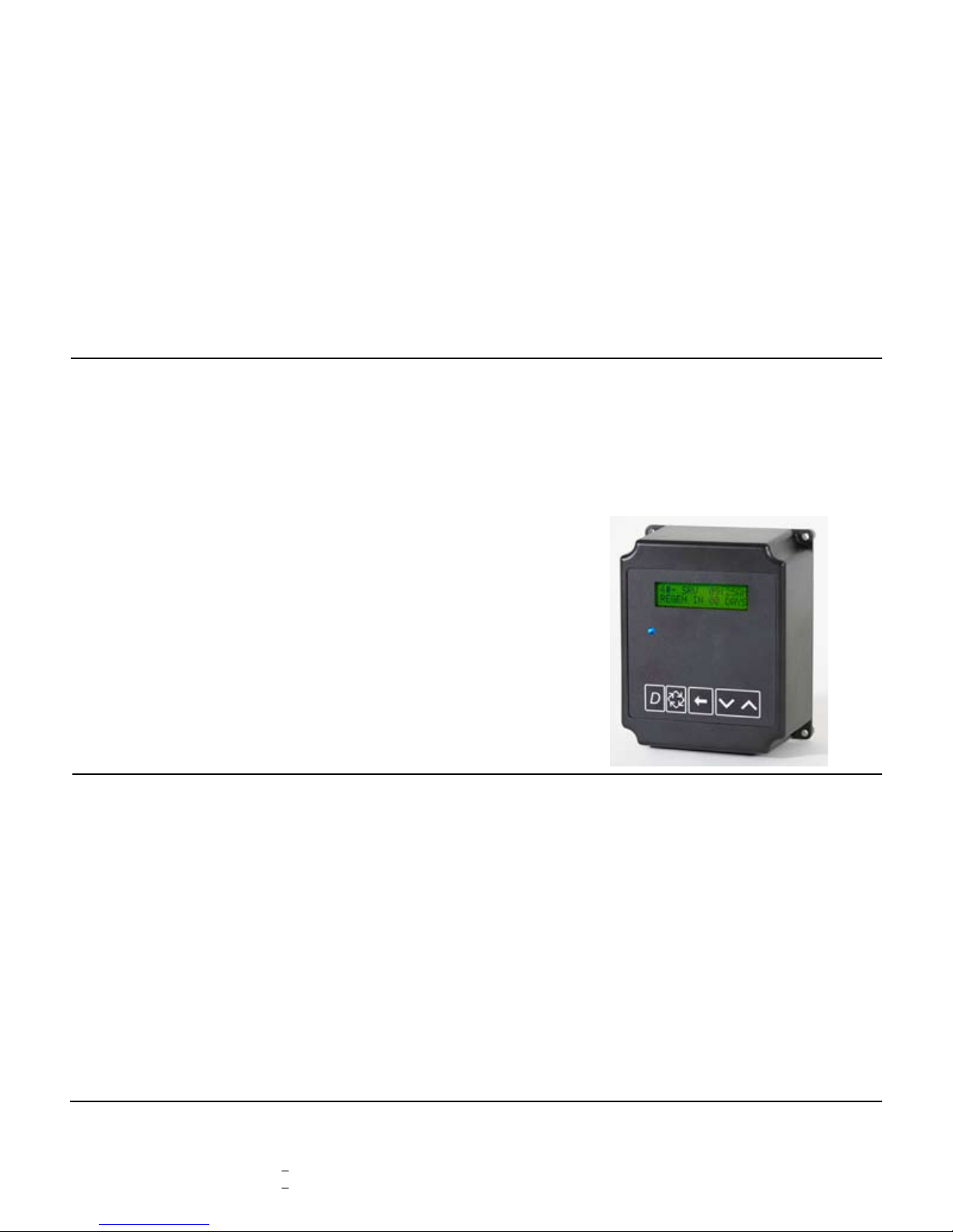
3200NXT Electronic Controller
The 3200NXT Network Controller uses on-board communications capabilities to link multiple valves (via off-the shelf CAT3,
CAT5, or better cables) for a variety of multiple system types as
described above.
Program Features:
• 2x16 character backlit LCD display
• Networks up to four units
• Auxiliary inputs and outputs
- Remote signal start input
- Remote lockout input
- Programmable relay output/chemical pump output
• Easy installation with plug-in wiring harnesses
• Front panel diagnostics button
- Flow rate
- Peak ow rate
- Totalizer
- Hours between last two regenerations.
- Hours since last regeneration
- Adjustable volume remaining
- Valve position
3. Twin, Tri-Plex & Four-Plex Demand Recall Progressive
Systems - 3214NXT Controller
• 2-4 Units
• Individual Meters
• Single or Individual Brine Systems
Three programming levels
• User mode
• Master programming
• Diagnostics mode
Note: The 3214NXT Demand Flow Network Controller is
used for demand recall applications.
3214NXT Demand Flow Network Controller
The 3214NXT Demand Flow Network Controller can be pro-
grammed to bring multiple units to the service position and back
to standby based on system demand ow. The 3214NXZT Demand Flow Network Controller used on-board communication
capabilities to link multiple valves via standard CAT3, CAT5, or
better communication cables.
Program Features:
• Network two to four valves
• Simple, on-site network programming
• Easy installation with plug-in wiring harnesses
• Shift key allows digit selecting in programming
• 2x16 character LCD backlit display
(letter or digit codes not needed)
• Valve, piston, and cam type default storage
Mechanical or Electronic Meter/Turbine Options:
Size Flow Ranges Accuracy
1.5” CC Meter 0.5 – 60 GPM +5%
2” CC Meter 1.5 - 150 GPM +5%
• User and master programming modes
• Diagnostic mode:
- Current ow rate
- Peak ow rate (can be reset)
- Totalizer (can be reset)
- Hours between last two regenerations
- Hours since last regeneration
- Volume remaining (adjustable)
- Valve addresses
Three programming levels
• User mode
• Master programming
• Diagnostics mode
Page 4
TNT Series
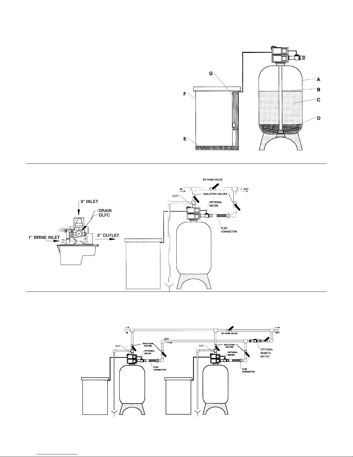
A. MINERAL TANK: Poly Glass™ Composite tank with Poly-
ethylene Inner Shell and Fiberglass Roving Manufactured to
Operate at 150 psi. NSF Approved.
B. DISTRIBUTOR SYSTEM: Three-Inch Hub & Lateral
Distribution for Maximum Service Flow and Minimal Pressure
Loss.
C. MINERAL: High Capacity Ion Exchange Resin. Uniform
and stable beads assure long life, high salt efciency, and
maximum hardness removal.
D. UNDERBEDDING: Multi-Layered Gravel Underbedding
assures full usage of mineral bed and allows for a smooth
and constant water ow for service and regeneration.
E. BRINE TANK: Rotationally Molded Polyethylene with
Dust-tight cover.
F. GRID PLATE: Grid plate allows for dry salt storage. Available in various sizes and heights.
G. OPTIONAL SAFETY BRINE VALVE: Acts as a Secondary Shut-Off for Timed Brine and may be used as a Primary
Shut-Off without Timed Brine.
Typical Single Tank Installation
TOP VIEW
Note: Steel tanks optional
Note:
1. Optional stainless steel ex
connectors are available for
inlet and outlet connections.
These are recommended
on systems utilizing Polyl-
glass composite tanks with
rigid piping such as copper,
galvanized, ect.
2. Union type connections are
recommended on the inlet
and outlet connections.
Twin Alternating Tank Installation
(Available with individual brine tanks as shown or with one twin brine tank.)
Note:
1. Optional stainless steel ex connectors are available for the inlet and outlet connection with each system and must
be installed on systems utilizing Polyglass™ composite tanks with rigid piping in copper, galvanized...etc.
2. Union type connections are recommended on the inlet and outlet connections.
Page 5
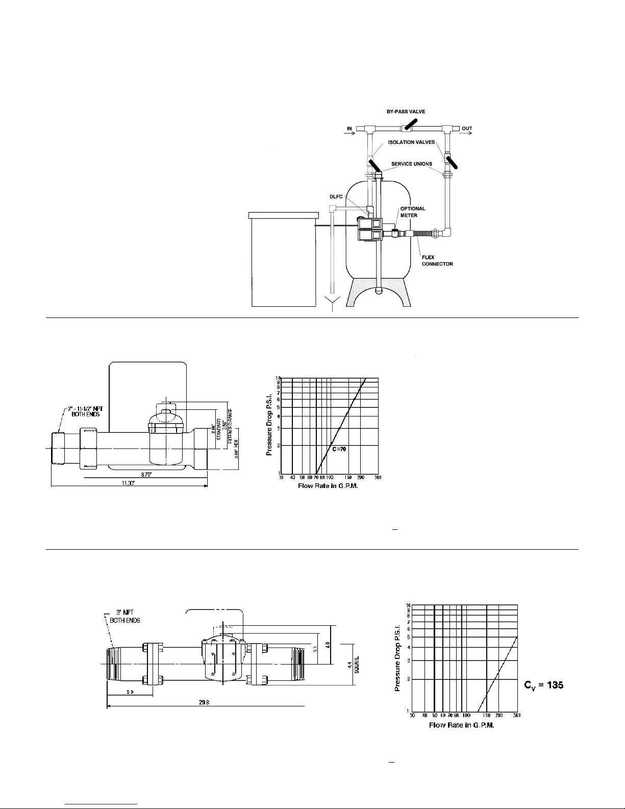
SideMount
Where ceiling heights may pose a restriction or a side-mounted conguration is preferred, TNT Series systems are available in this
design conguration. Factory pre-piped and pressure tested, these system designs must be shipped either skid mounted or have
face piping dis-assembled for shipment and re-assembled at the job site. Available with non-corrosive polyglass composite tanks or
steel. Consult factory for details.
Skid mounted and
factory pre-piped
Optional skid mounted system
design congurations with or
without factory interconnecting
piping for twin or tri-plex system
designs are available, in both
top-mount or side-mount design
congurations.
2” Meter
2” Meter and Flow/Pressure Loss Data
2” Brass Meter
■ Standard Range 1,250 Gal. Min. to 21,250 Gal. Max. ■ Flow accuracy –– +5% from 3 to 150 GPM
■ Extended Range 6,250 Gal. Min. to 106,250 Gal. Max. ■ Dimensions & Flow Data are the same with NT Microprocessor
3” Meter
3” Meter and Flow/Pressure Loss Data
■ Standard Range 3,750 Gal. Min. to 63,750 Gal. Max. ■ Flow accuracy –– +5% from 7 to 300 GPM
■ Extended Range 18,750 Gal. Min. to 318,750 Gal. Max. ■ Dimensions & Flow Data are the same with NT Microprocessor
■ Other meters available, consult factory
Page 6
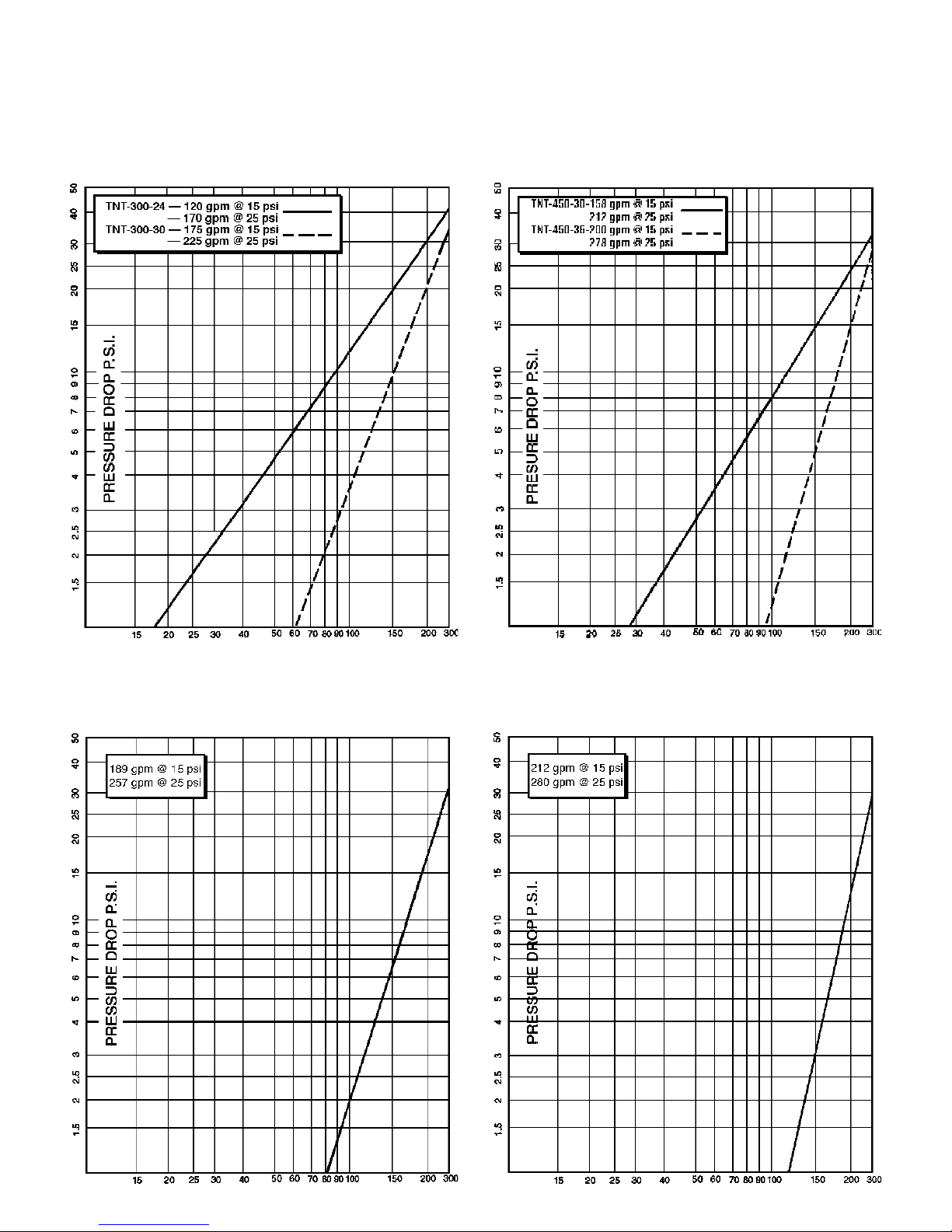
TNT Service Rates & Pressure Drop Charts
TNT-300 3” Service Rates
& Pressure Drop Chart
11/92
TNT-450 3” Service Rates
& Pressure Drop Chart
11/92
FLOW RATE G.P.M.
TNT-600 3” Service Rates
& Pressure Drop Chart
11/92
FLOW RATE G.P.M.
TNT-750 3” Service Rates
& Pressure Drop Chart
11/92
FLOW RATE G.P.M.
FLOW RATE G.P.M.
Page 7
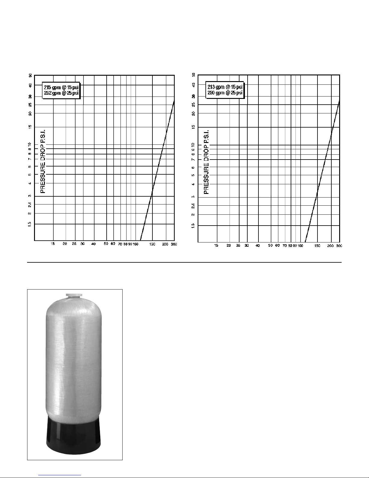
Pressure Drop Charts
TNT-900-48 3” Service Rates
& Pressure Drop Chart
11/92
TNT-1200 3” Service Rates
& Pressure Drop Chart
11/92
FLOW RATE G.P.M.
Commercial/Industrial Tanks
High Grade Polyethylene Tank Liner
• Fiber-free inner surface suitable for all standard water treatment applications.
• Offers wide chemical resistance; not adversely affected by regenerating
chemicals.
Strong, Filament Wound Outer Laminate
• Continuous strands of berglass reinforced with high strength epoxy resin.
• Rustproof and corrosion-resistant
Operating Parameters
• Maximum operating pressure: 150 PSI (10.2 BAR)
• Maximum operating temperature: 120ºF (49ºC)
Industry Approved
• Tanks designed and tested to meet industry standards, ensuring top eld
performance:
- NSF
Warranty
• All commercial/light industrial tanks are backed by an exclusive limited manufacturer's
- Sizes 24” through 48”: 5 year limited warranty
®
Standard 44
warranty:
FLOW RATE G.P.M.
Page 8
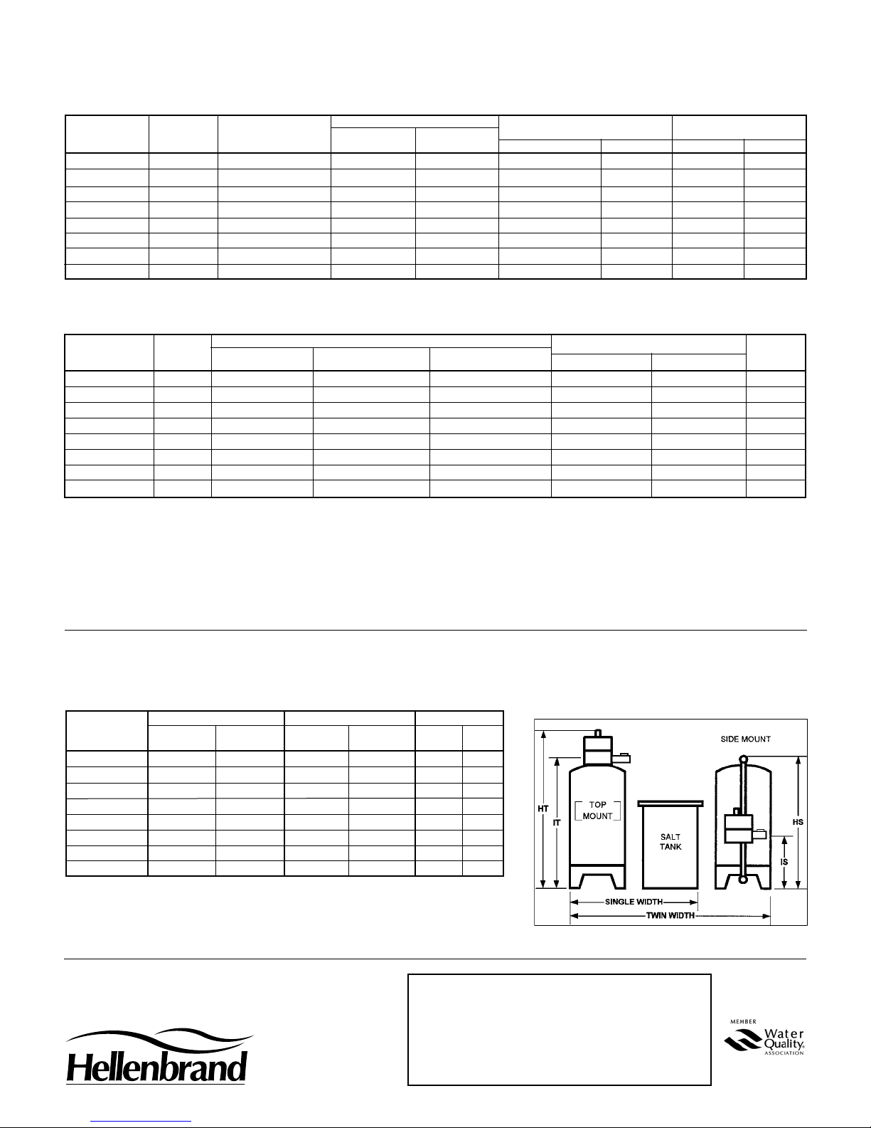
TNT Physical Specications
Mineral tank sizes shown are with composit/FRP tanks.
RECOMMENDED BRINE TANK MINERAL TANK APPROXIMATE
PIPE SIZE MINERAL TANK SIZE
MODEL (INCHES) (INCHES) (INCHES) ( LBS) 1/4" X 1/8" #20 SINGLE TWIN
TNT-300-24 3 24 X 72 30 X 50 1,110 0 150 1085 2145
TNT-300-30 3 30 X 72 30 X 50 1,110 200 75 1160 2295
TNT-450-30 3 30 X 72 39 X 48 2,030 200 75 1600 3120
TNT-450-36 3 36 X 72 39 X 48 2030 300 150 1835 3590
TNT-600 3 36 X 72 39 X 48 1,640 300 150 2115 4135
TNT-750 3 42 X 72 42 X 60 2,580 500 175 3475 6325
TNT-900 3 42 X 72 50 X 60 4,130 500 175 4280 8560
TNT-1200 3 48 X 72 50 X 60 3,495 700 200 4800 8760
SALT STORAGE
GRAVEL UNDERBEDDING SHIPPING WEIGHT
TNT Capacity Ratings
RATED CAPACITY FLOW RATES (gpm)
RESIN LOW SALT MEDIUM SALT HIGH SALT BKW
MODEL CU.FT. GRAINS/LBS GRAINS/LBS GRAINS/LBS 15 PSI 25 PSI GPM
TNT-300-24 10 190,000/60 280,000/100 320,000/150 120 170 12
TNT-300-30 10 190,000/60 280,000/100 320,000/150 175 225 20
TNT-450-30 15 285,000/90 420,000/150 480,000/225 158 212 20
TNT-450-36 15 285,000/90 420,000/150 480,000/225 200 278 30
TNT-600 20 380,000/120 560,000/200 640,000/300 189 257 30
TNT-750 25 475,000/150 700,000/250 800,000/375 212 280 40
TNT-900 30 570,000/180 840,000/300 960,000/450 215 282 50
TNT-1200 40 760,000/240 1,120,000/400 1,280,000/600 213 280 50
1. Steel tank design congurations available up through 60” tank diameters. Consult factory for details.
OPERATING CONDITIONS
1. Water Pressure 30 - 100 psi.
2. Water temperature is not to exceed 110°F and the unit cannot be subject to freezing conditions. Consult factory for higher water
temperature applications.
3. Limit of 2 ppm of Ferrous Iron. Add 3 grains per gallon of hardness for each ppm of iron present.
4. Flex connectors and vacuum breakers are required when using the PolyGlass Composite mineral tanks.
5. Backwash ow rates are calculated at 4 gpm per sq. ft. of bed area and rounded off based on 50ºF water temperature.
TNT Series Fiberglass Dimensions
with Six-Inch Flange Opening
HEIGHT INLET/OUTLET HEIGHTS SUGG. WIDTH
TOP MOUNT SIDE MOUNT TOP MOUNT SIDE MOUNT SINGLE TWIN
MODEL HT* HS** IT IS
TNT-300-24 101 87.5 82.5 51 62 99
TNT-300-30 101 87.5 80 51 68 108
TNT-450-30 112 96.5 80 51 83 117
TNT-450-36 112 97 81 51 83 129
TNT-600-36 112 97 81 51 83 129
TNT-750-42 113 104.5 92 51 92 144
TNT-900 113 104.5 92 51 92 144
TNT-1200-48 116 103 93 51 106 164
All dimensions ±1” and are subject to change without notice. Use as reference only.
*Allow additional 12” for resin lling on HT dimension.
**Allow additional 18” for resin lling on HS dimension.
Call factory for optional tank & dimensional congurations.
Product Improvement designs are subject to change without notice.
HELLENBRAND, INC.
1-800-626-1417
www.hellenbrand.com
DEALER NAME:
73-054
9/08-LBRY
 Loading...