

Hellenbrand TNT User Manual
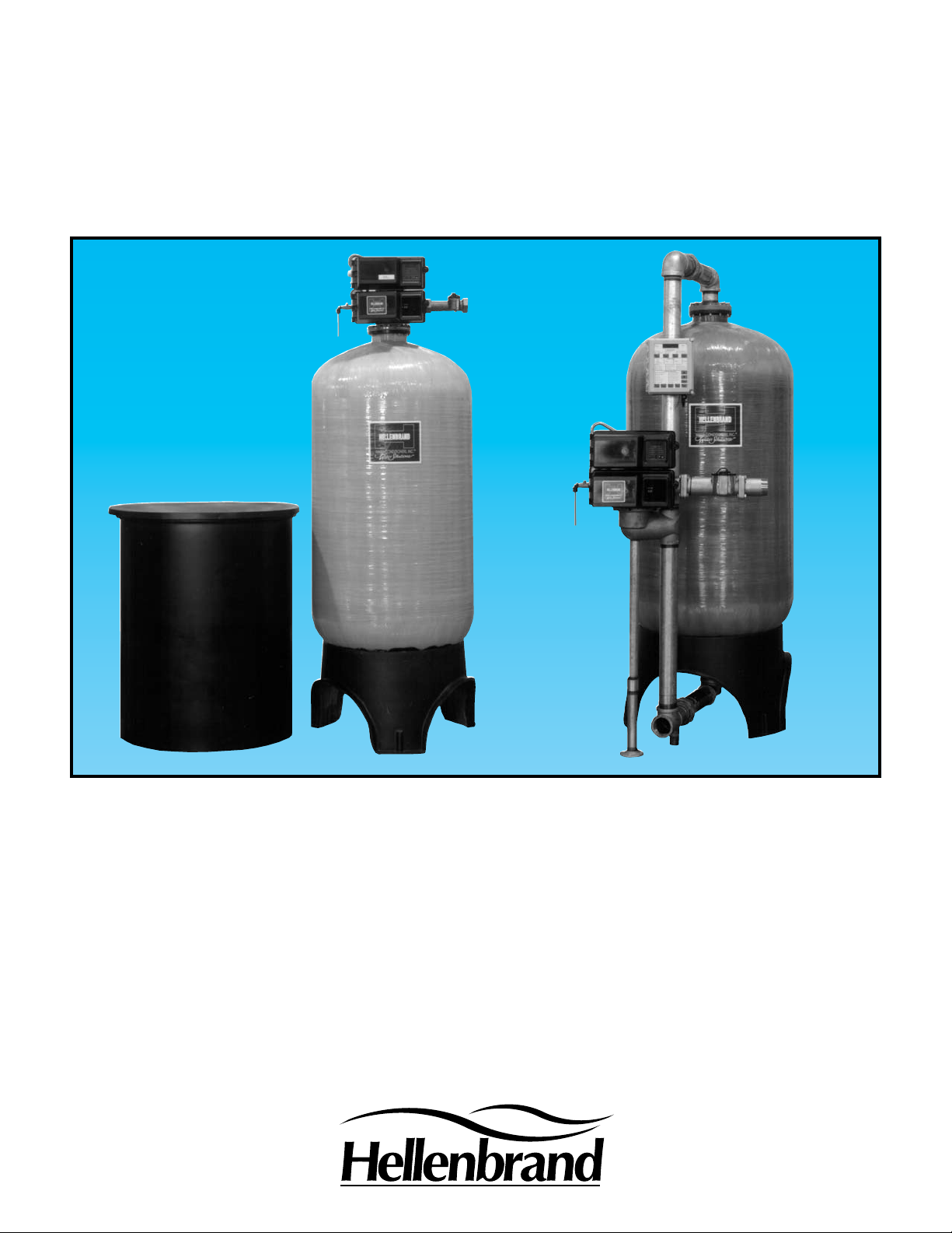
TNT SERIES
WATER CONDITIONERS
For Commercial & Industrial Applications
Apartment Buildings
Boiler Water Treatment
Car Washes
Commercial Buildings
Condominiums
Factories
Hospitals
Laundries
Mobile Home Parks
Motels and Hotels
Nursing and Rest Homes
Ofce Buildings
Restaurants
Schools
Hellenbrand Means
Quality and Reliability
Since 1967, Hellenbrand Water Conditioners, Inc. has provided water solutions to the water treatment industry in the
U.S. and around the world. We have developed a complete line of high quality products. An excellent example of this,
is the Hellenbrand TNT Series Conditioners.
TNT Series Conditioners use a anged top-mounted or optional side-mounted adapter, three-inch NPT inlet and outlet
solid brass control valve with a motor-driven, time-tested, hydraulically-balanced piston with a seal and spacer concept
to pilot service ow not dependent on water pressure. No diaphragms to rupture or false transfer. It will provide up to
170 gpm hard water by-pass during regeneration, or you may have the optional “no hard water by-pass piston” for twin
or multiple systems. These high service ow rates, the simplied alternating and multiple lockout systems, eliminate the
need for diaphragms, solenoids and stagers. The ve cycle TNT controller is available with either downow (co-current)
or upow (counter-current) brining, with easy adjustable cycle times. The TNT Series offers you a choice of mechanical
or microprocessor controlled meter demand systems, with two-inch or three-inch meter turbines. All systems are factory-wired and tested electrically to assure easy installation and correct operation.
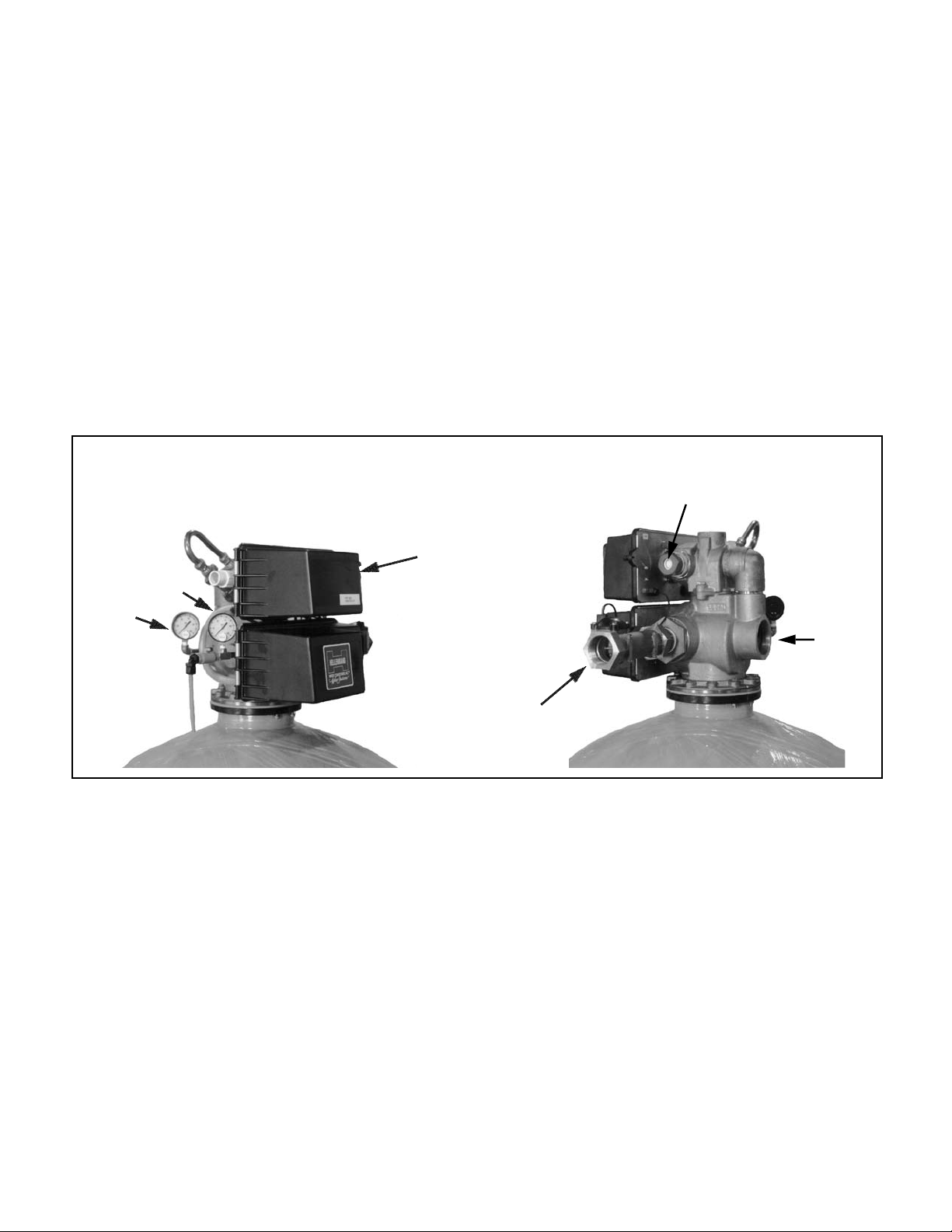
FRONT VIEW
Optional Inlet & Outlet Pressure Gauges & Soft Water
Test Port
Controller
Outlet
Inlet
Optional Factory Installed Vacuum
Breaker
Optional
2” Meter Outlet
BACK VIEW
TNT Series Control Valve -Three Inch Inlet/Outlet
1. Stainless Steel Backplate will not rust or corrode.
2. Factory provided Drain Line Flow Control maintains
accurate backwash rates.
3. Three-Inch NPT Inlet & Outlet Connections.
4. Solid Brass Valve assures durability and long life.
5. Hydraulically-balanced Piston, Seal, and Spacers.
Lower service piston is available with or without hard
water by-pass. Non-sticking Teon-coated Piston al-
lows foreign particles to pass through without damaging
the unit.
6. Upper Piston pilots the regeneration steps of backwash,
brine and slow rinse, fast rinse, and brine tank rell.
7. Separate “Time-ll” Brining with accurate ow controls
allows automatic brine tank rell. Brine Tank Rell
Rates are easily adjustable on the cycle programmer. No need to worry about adjusting oat valves or
repositioning brine plugs for salt measurements.
8. Heavy-duty Drive Motor receives signal from timer
to efciently direct water ow during regeneration.
Piston shifts smoothly and quietly regardless of water
pressure.
9. Lower Heavy-duty Drive Motor receives signal from
upper drive motor to direct the service piston into position. Piston shifts smoothly and quietly regardless of
water pressure.
10. TNT Series Timer provides fully automatic, dependable timing for regeneration. The Cycle Programmer
regulates all regeneration cycles which are easily
adjustable. For manual regeneration start, simply turn
the service indicator clockwise.
Inlet
TN2 Standard System Design Options
(for more specic information on the various system designs, contact your local Hellenbrand representative or go to: www.hellenbrand.com
1. Single Tank Systems - XT Controller
• Time Clock
• XT Controller Electronic Meter Demand
Twin, Tri-Plex & Four-Plex Systems - 3200NXT Controller
2.
Parallel Operation
• 2-4 Units
• Individual Meters
• Single or Individual Brine Systems
Alternating Operation
• 2-4 Units
• Twin Systems - One Meter or Two Meters
• Tri-Plex & Four-Plex Systems - Individual Meters
• Single or Individual Brine Systems
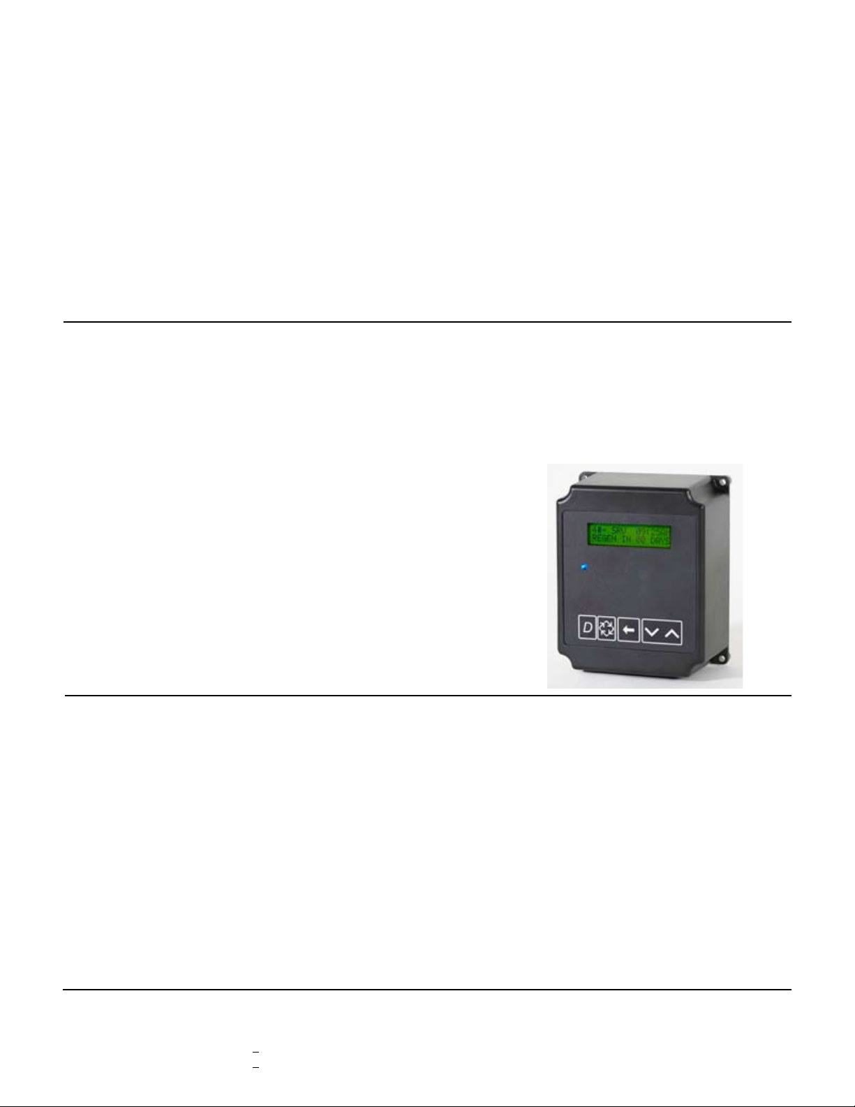
3200NXT Electronic Controller
The 3200NXT Network Controller uses on-board communications capabilities to link multiple valves (via off-the shelf CAT3,
CAT5, or better cables) for a variety of multiple system types as
described above.
Program Features:
• 2x16 character backlit LCD display
• Networks up to four units
• Auxiliary inputs and outputs
- Remote signal start input
- Remote lockout input
- Programmable relay output/chemical pump output
• Easy installation with plug-in wiring harnesses
• Front panel diagnostics button
- Flow rate
- Peak ow rate
- Totalizer
- Hours between last two regenerations.
- Hours since last regeneration
- Adjustable volume remaining
- Valve position
3. Twin, Tri-Plex & Four-Plex Demand Recall Progressive
Systems - 3214NXT Controller
• 2-4 Units
• Individual Meters
• Single or Individual Brine Systems
Three programming levels
• User mode
• Master programming
• Diagnostics mode
Note: The 3214NXT Demand Flow Network Controller is
used for demand recall applications.
3214NXT Demand Flow Network Controller
The 3214NXT Demand Flow Network Controller can be pro-
grammed to bring multiple units to the service position and back
to standby based on system demand ow. The 3214NXZT Demand Flow Network Controller used on-board communication
capabilities to link multiple valves via standard CAT3, CAT5, or
better communication cables.
Program Features:
• Network two to four valves
• Simple, on-site network programming
• Easy installation with plug-in wiring harnesses
• Shift key allows digit selecting in programming
• 2x16 character LCD backlit display
(letter or digit codes not needed)
• Valve, piston, and cam type default storage
• User and master programming modes
• Diagnostic mode:
- Current ow rate
- Peak ow rate (can be reset)
- Totalizer (can be reset)
- Hours between last two regenerations
- Hours since last regeneration
- Volume remaining (adjustable)
- Valve addresses
Three programming levels
• User mode
• Master programming
• Diagnostics mode
Mechanical or Electronic Meter/Turbine Options:
Size Flow Ranges Accuracy
1.5” CC Meter 0.5 – 60 GPM +5%
2” CC Meter 1.5 - 150 GPM +5%
 Loading...