

Hellenbrand S-12-024, S-12-032, S-12-048, S-12-064, S-12-DMT-032 Supplemental Programing & Cover Manual
S-12 Series
BATTERY AND SOLAR SYSTEMS
Supplemental Programing & Cover Manual
Web: www.hellenbrand.com • Email: info@hellenbrand.com
800377
6/10/16-LBRY
©2011-2016
Manufactured by:
HELLENBRAND, INC.

Page 2 SD Manual
Table of Contents
Specications ................................................................................................................................................... 3
Front Cover and Drive Assembly ....................................................................................................................... 4
Wiring Diagram ................................................................................................................................................ 5
Regeneration and Error Screens, Button Operations and Functions ................................................................... 6
User Displays ................................................................................................................................................... 7
Conguration Settings .................................................................................................................................... 8-9
Setting Regeneration Cycle Times ................................................................................................................... 10
Installer Display Settings ............................................................................................................................ 11-12
Diagnostics .................................................................................................................................................... 13

Page 3 SD Manual
FACTORY REGENRATION SETTINGS (BOLD)
8 8 8 8 8
60 60 60 60 60
6 6 6 6 1
6 6 6 6 6
Total Regeneration Gallons
3 (4.5#) 4 (6#) 6 (9#) 8 (12#) 4 (6#)
6.7 (10#)
High Salt 7.5 (11#) 10 (15#) 15 (22.5#) 20 (30#) 10 (15#)
17,200 22,930 34,400 45,860 22,930
28,060
High Salt 24,230 32,310 48,460 64,620 32,310
Peak @ 15 psi 13.1 13 14.1 18.2 14.1
Injector Size C-Violet D-Red E-White G-Yellow E-White
*Factory Settings are in BOLD
S12 Specifications
S12 Specications
Model # S-12-024 S-12-032 S-12-048 S-12-064 S-12-DMT-032
Backwash #1 Minutes
Brine/Rinse Minutes
Backwash #2 Minutes
Fast Rinse Minutes
including Brine
Refill Minutes (LBS of salt)
Low Salt
Medium Salt 5 (7.5#) 6.7 (10#) 10 (15#) 13.5 (20#)
Capacity Grains Grains Grains Grains Grains
Low Salt
Medium Salt 21,040 28,060 42,090 56,120
Service Flow Rates GPM GPM GPM GPM GPM
Continuous @ 10 psi 9.8 10.1 10.5 14.2 10.5
Flint Under bed (lbs.) 8 11 14 40 N/A
High Capacity Resin (cu.ft.) 0.75 1 1.5 2 1
Resin Tank Size 8x44 9x48 10x54 13x54 10x54 Dual
Recommended Brine Tank 18X40 18X40 18x40 18x40 18X40
Brine Line Size 3/8” 3/8" 3/8" 3/8" 3/8"
DLFC (gpm) 1.3 1.7 2.2 4.2 2.2
BLFC (gpm) 0.5 0.5 0.5 0.5 0.5
41 51 64 64 51
**Water usage at 40 psi inlet pressure. Brine make-up water not included.
Factory setting are for clean, iron free water for efficient salt use.
Higher salt setting are recommend for iron levels over 0.5 ppm

Page 4 SD Manual
SD Front Cover and Drive Assembly
Drawing No. Order No. Description Quantity
1 V3175SP-01 WS1SP FRONT COVER ASSEMBLY 1
2 102096 WS1 MOTOR 1
3 101262 WS1 DRIVE BRACKET & SPRING CLIP 1
4 111412 WS1THRU2 SD REPL 1
5 101746 WS1 DRIVE GEAR 12X36 3
6 101459 WS1 DRIVE GEAR COVER 1
7 111413 D CELL ENCLOSURE SD VALVES 1
Refer to Control Valve Service Manual for other drawings and part numbers.
When replacing the battery, align
positives and push down to fully seat.
Correct
Battery
Orientation
Battery replacement
is 3 volt lithium coin
cell type 2032.
Battery Fully Seated
2
4
1
Battery
Connection
5
3
6
7
6 - non-rechargeable
Alkaline D Cell
Batteries required.
Not included.
Connection to circuit board
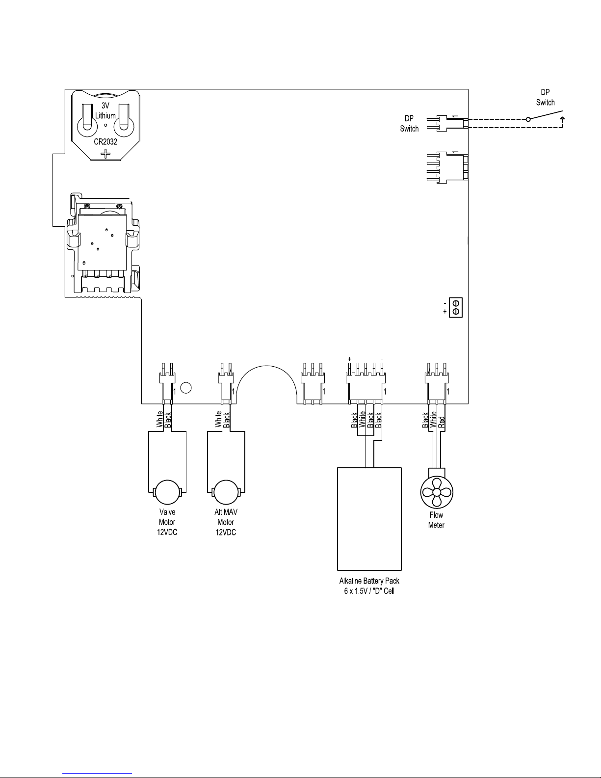
Page 5 SD Manual
SD Wiring Diagram
 Loading...