

Hellenbrand Iron Storm 10, Iron Storm 12, Iron Storm 13 User Manual
STO
RM
ProMate-6.0 Iron Curtain Storm Series
404 Moravian Valley Road • Waunakee, Wisconsin 53597
www.hellenbrand.com • info@hellenbrand.com
Consumer’s Filter Manual
p/n 111701 Rev. B
Updated 10/30/17
© 2017
Manufactured by:
HELLENBRAND, INC.

This owner’s manual is designed to assist owners and
of your new water lter. It is our sincere hope that this manual is clear, concise and helpful. Detailed instructions
on general operating conditions, pre-installation and installation instructions, start-up, and meter programming are
included. We have included a troubleshooting guide, service instructions and parts diagrams to assist future needs.
In the event that you need professional assistance for servicing your water lter, please contact the dealer
who installed this system.
installers with the operation, maintenance and installation
TABLE OF CONTENTS
General Specications..............................................................................................................................................3
Pre-Installation Check List ........................................................................................................................................ 4
Bypass Valve Operation ...........................................................................................................................................4
Startup Instructions...................................................................................................................................................5
Operating Conditions ................................................................................................................................................ 5
Specications ...........................................................................................................................................................5
Programming ............................................................................................................................................................6
Displays/Settings ......................................................................................................................................................6
Set Time of Day ........................................................................................................................................................7
Trouble Shooting ......................................................................................................................................................8
Ozone Trouble Shooting ...........................................................................................................................................8
Parts Diagrams & Installation Fittings..................................................................................................................9-13
Recommended Annual Maintenance...................................................................................................................... 14
Air Regen Specications ........................................................................................................................................15
Warranty .................................................................................................................................................................16
Dealer Name __________________________________________________ Phone _______________________________
Address _______________________________________________________ Email ________________________________
____________________________________________________________________________________________
2

GENERAL SPECIFICATIONS
OPERATING PRESSURES
Minimum/Maximum ................................................................................................................ Minimum 25 psi
Optimum Range 40-65 psi
Maximum 100 psi
OPERATING TEMPERATURES
Minimum/Maximum ................................................................................................................ 40º - 110º F
METER
Accuracy ................................................................................................................................±5%
Flow Rate Range ...................................................................................................................0.25 - 27 GPM
Gallon Range .........................................................................................................................20 - 50,000
DIMENSIONS
Drain Line ............................................................................................................................... 3/4” or 1” NPT
Ozone Check Valve ................................................................................................................3/8” Poly Tube
ELECTRICAL CURRENT DRAW AND VOLTAGE .............................................................................. 2.0A/120V
NOTE: Operating outside of the optimum pressure range may affect system function. Contact your Hellenbrand
support team for information.
3
PRE-INSTALLATION CHECK LIST
(All electrical & plumbing should be done in accordance to all local codes)
Storm is limited to indoor installations
Water Pressure: A minimum of 25 pounds of water pressure
(psi) is required for regeneration. Maximum pressure 100 psi.
Water Quality: On rural water supplies there is often a problem
with sand or sediment in the water. (This problem occasionally
occurs in public water supplies.) Sand and sediment may plug
the lter, restricting the ow through the media bed. Note: Well
and/or pump problems affecting the operation of the lter and
repairs are not covered under the warranty.
Electrical: A continuous 110 volt/60 cycle current supply is
required. Make certain the current supply is uninterrupted and
cannot be turned off with another switch. All electrical connections must be connected per local codes. Surge protection is
recommended with all electrical controls.
Existing Plumbing: Condition of existing plumbing must be
free from lime and iron build-up. Piping that is built-up heavily
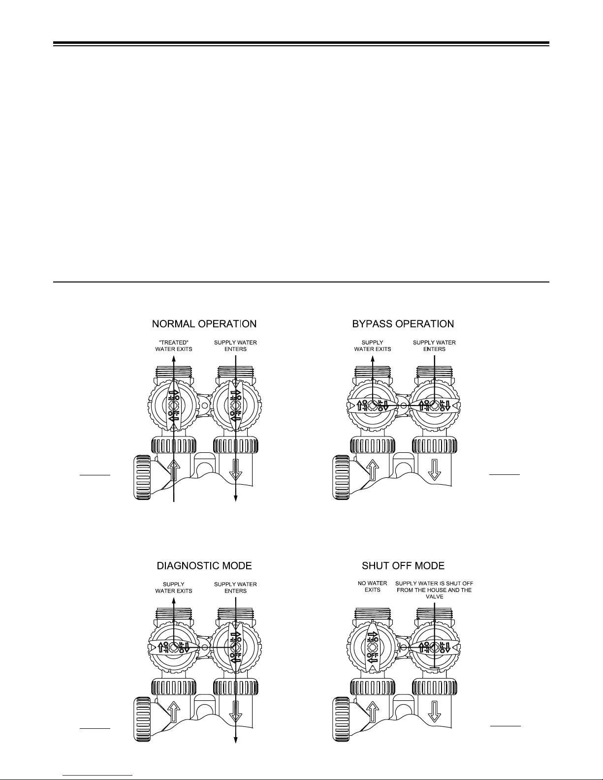
BYPASS VALVE OPERATION
Softening - Filtering
with lime and/or iron must be replaced. If piping is blocked with
iron, additional equipment may be needed ahead of the lter to
correct the problem.
Drain Line: The lter should be located close to a drain. Avoid
overhead drain lines if possible to prevent back pressure. Overhead drains are not to exceed 8 feet above the oor and no more
than 20 feet in length. The pipe size for the drain line should be
a minimum of 3/4”. Backwash ow rates in excess of 10 gpm
or length in excess of 20’ require 1” drain line.
Bypass Valves: Always provide for the installation of a bypass
valve.
Caution: Water temperature is not to exceed 110°F; the lter
cannot be subject to freezing conditions, or to a vacuum due to
loss of pressure (such as a water main break).
Figure 1
Figure 3
Figure 2
Figure 4
4
Start Up Instructions
For optimal results, allow the lter media to soak for a
minimum of 12 hours prior to install. This
tain the manufacturer’s specied
1. Complete all plumbing connections; inlet, outlet and drain
line.
2. Place bypass valve in bypass position. Turn on main
water supply and open a cold ltered faucet to ush piping
of any air and/or foreign material. Run until water is clear.
3. Open inlet valve slowly on bypass until it is in fully open
service position. Let water run to drain until
unit into 120V outlet and remove cover and plug transformer connection into 4-prong connection
labeled power. Valve will return to service position once
this connection is made.
4. Let media soak for 15 minutes before proceeding.
ltration properties.
helps to main-
clear. Plug
on circuit board
Operating Conditions
pH — The pH level of the inuent water must be 7.0 or higher
for iron oxidation reaction to proceed per the engineering
specications.*
Iron — This system is rated for 6.0 ppm of ferrous (clear water)
and/or ferric (red water) iron.*
Hydrogen Sulde — Sometimes referred to as "rotten egg" odor.
This system is rated for 5.0 ppm hydrogen sulde. Hydrogen
sulde levels vary depending on barometric pressure.*
Manganese — Limit 1.0 ppm; amounts present over 1.0 ppm may
gradually prevent iron removal. Note: For optimum manganese
reduction, pH should be greater than 8.5.*
Organic Matter (Tannins) – The presence of organic matter such
as tannins will prevent the oxidation process of converting the
dissolved element, such as iron or manganese, to a nonsoluble
precipitate or solid substance. In other words, organics can tie
up the iron preventing ltration. The presence of organics such
as tannins above 0.5 ppm voids any claims for this system
to perform as stated above. In some applications, tannin
levels below 0.5 ppm or the presence of other organics may
hinder the operation of this system.*
5. Initiate backwash by holding “REGEN” button down until
piston movement is heard.
6. Let backwash continue until cycle is done. When “RINSE”
is displayed, push the REGEN button again to move into
the SERVICE position. Let the system settle for 5 minutes.
7. Repeat the backwash and settle steps (5&6) for a total of
three times.
NOTE: It takes several backwash cycles before all the media
nes are removed. Elimination of the 12 hour soak procedure
may result in more backwash cycles required to remove the
media nes.
Failure to follow proper start-up may result in
equipment malfunction not covered by warranty.
Total Dissolved Solids (TDS) — While TDS does not directly
affect iron removal, it is a good indicator of potential interference.
Most waters have TDS less than 500 and generally present no
problems to iron reduction. If any ion becomes excessive, it may
cause failure of iron removal. A TDS more than 500 ppm voids
any claims for this system to perform as stated above.*
*For application parameters outside the specied operation
conditions or additional information regarding the listed
items, contact your dealer.
Do not install on chlorinated water supplies - harmful byproducts may be formed with ozone.
This unit is not intended to aid in the mitigation of microorganisms and is not duly registered as a pesticidal device.
The Storm ozone lter must not be used on bacteriologically unsafe water supplies, such as those with with
positive Coliform or E Coli bacteria tests.
Small amounts of hardness (0.5-2 gpg) may occur initially
when lters installed on soft water.
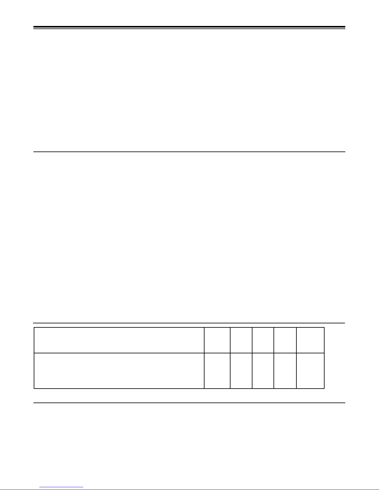
Specications
Iron Storm Models
Iron Storm-10 10"x54" 1.0 1" 4 5.3
Iron Storm-12 12"x52" 1.6 1" 6 7.5
Iron Storm-13 13"x54" 1.9 1" 7 10
(1) Water temps above 60° F will require a higher backwash rate. Consult factory.
Backwash Frequency
Iron Applications
0.3 - 2.0 ppm Iron - Every 3rd Day
2.0 - 4.0 ppm Iron - Every Other Day
4.0 - 6.0 ppm Iron - Every Day
5
Filter
Tank
Size
Media
Cu. Ft
Inlet/
Outlet
Max.
Service
Flow
GPM
(1)
Backwash
Rate
GPM
Ozone Recharge Frequency
Hydrogen Sulde Applications
0.1 - 1.0 ppm Hydrogen Sulde - 100 Gallon
1.0 - 5.0 ppm Hydrogen Sulde - 50 Gallon
 Loading...