

Page 1
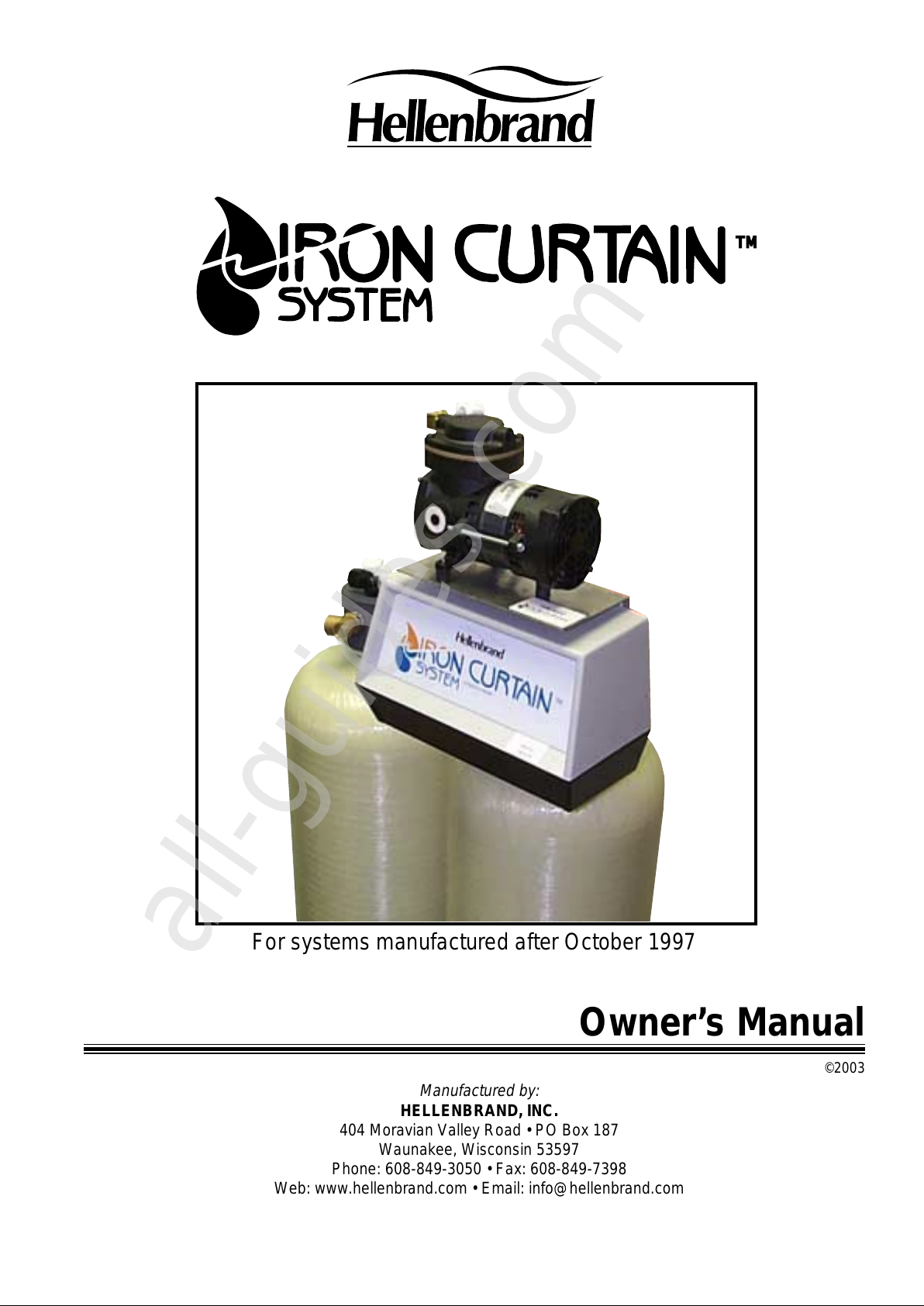
For systems manufactured after October 1997
Manufactured by:
HELLENBRAND, INC.
404 Moravian Valley Road • PO Box 187
Waunakee, Wisconsin 53597
Phone: 608-849-3050 • Fax: 608-849-7398
Owner’s Manual
©2003
TM
All manuals and user guides at all-guides.com
all-guides.com
Page 2
2
Congratulations
on your purchase of one of the finest water treatment systems available today – the Iron
Curtain System. This patented, non-chemical filter system, when properly applied will remove iron, manganese and/or
hydrogen sulfide from your water supply. The Iron Curtain has been third-party tested by the Water Quality Association. An
optional "Type A" filter also corrects low pH water.
This owner’s manual is designed to assist owners and installers with the operation, maintenance, and installation of your new iron
removal system. It is our sincere hope that this manual is clear, concise, and helpful to both owner and installer. We have included
detailed instructions of general operating conditions, pre-installation, installation, start-up, and timer settings.
Questions?
Should you have any questions regarding the installation, operation or servicing of this system, please
contact the dealer you purchased this system from. Your dealer will be familiar with your particular situation, your water
conditions, etc. and should be able to address your concerns promptly and efficiently.
TABLE OF CONTENTS
Installation Data ..........................................................................................................................................................................3
Air Recharge & Air Bleed-Off Valve Fitting Connection Assy. ....................................................................................................3
Aeration Head Fitting Connection ...............................................................................................................................................3
Principle of Operation ................................................................................................................................................................. 4
Operation of Aeration Pump ....................................................................................................................................................... 4
Advantages Over Other Systems ............................................................................................................................................... 4
Operating Conditions ..................................................................................................................................................................5
General Application Guidelines................................................................................................................................................... 5
Pre-Installation Check List ..........................................................................................................................................................6
Installation Instructions ............................................................................................................................................................... 6
Start-up ....................................................................................................................................................................................6-7
Regeneration Frequency ............................................................................................................................................................ 7
Specifications .............................................................................................................................................................................. 7
Type A Iron Curtain Systems ...................................................................................................................................................... 7
Instructions for Adding IC pH Correction Media.......................................................................................................................7-8
Installation Diagrams ...............................................................................................................................................................8-9
How to Set Timer ........................................................................................................................................................................9
How to Set Regeneration Time ................................................................................................................................................. 10
How to Manually Regenerate Your Water Filter ....................................................................................................................... 10
How To Manually Advance Control Center ............................................................................................................................... 10
How to Set Regeneration Cycle Program .................................................................................................................................11
Iron Curtain System Diagram.................................................................................................................................................... 12
Iron Curtain Wiring Diagram ..................................................................................................................................................... 12
Iron Curtain Timer Assembly .................................................................................................................................................... 13
Iron Curtain Control Drive Assembly......................................................................................................................................... 14
Iron Curtain Aeration Pump Diagram ........................................................................................................................................ 15
Iron Curtain Aeration Pump Repair Instructions ....................................................................................................................... 16
IC-10 Series Control Valve Assembly ....................................................................................................................................... 17
IC-12 Series Control Valve Assembly ....................................................................................................................................... 18
Instructions for Replacing Piston Assy. & Seal Kit ...............................................................................................................19-21
Iron Curtain Flow Diagrams .................................................................................................................................................22-24
Troubleshooting ...................................................................................................................................................................25-26
Winterizing Iron Curtain Systems.............................................................................................................................................. 27
Iron Curtain Limited Warranty ...................................................................................................................................................28
All manuals and user guides at all-guides.com
Page 3
3
INSTALLATION DATA
Date of Installation _______________________________________ Model No.___________________________________
Address of Installation ___________________________________________________________________________________
Installed By_____________________________________________________________________________________________
Raw Water Test: Iron_______ Manganese_______ pH_______ Hydrogen Sulfide_______
TDS_______ Iron Bacteria_______ yes _______ no Tannins_______
Automatic Regeneration: Every _______ Days
Influent Flow Rate @ 25 PSI _______ Gallons Per Minute (gpm)
Regeneration Program Settings*
Factory Number Program Wheel Customized
Cycle Preset Setting Pins/Spaces Location Setting
Backwash 12 minutes 6 pins 10 - 20 ______ minutes
Air Recharge Cycle 18 minutes total 9 spaces 22 - 38 ______ minutes
Pre Bleed-off 4 minutes 2 spaces 22 - 24 ______ minutes
Air Recharge/
Bleed-off 10 minutes 5 spaces 26 - 34 ______ minutes
Air Pump Run Time 10 minutes 5 pins extending out back
of program wheel 0 - 8 ______ minutes
Post Bleed-off 4 minutes 2 spaces 36 - 38 ______ minutes
Rapid Rinse 6 minutes 3 pins 40 - 44 ______ minutes
Cycle Advance 4 minutes 2 spaces 46 - 48
Cycle Shut Off 4 minutes 2 pins 50 - 52
*Refer to page 11 for instructions if altering factory settings.
Note: Five pins extending out back of program wheel (0 - 8 program wheel location) are synchronized with bleed-off spaces 26 - 34.
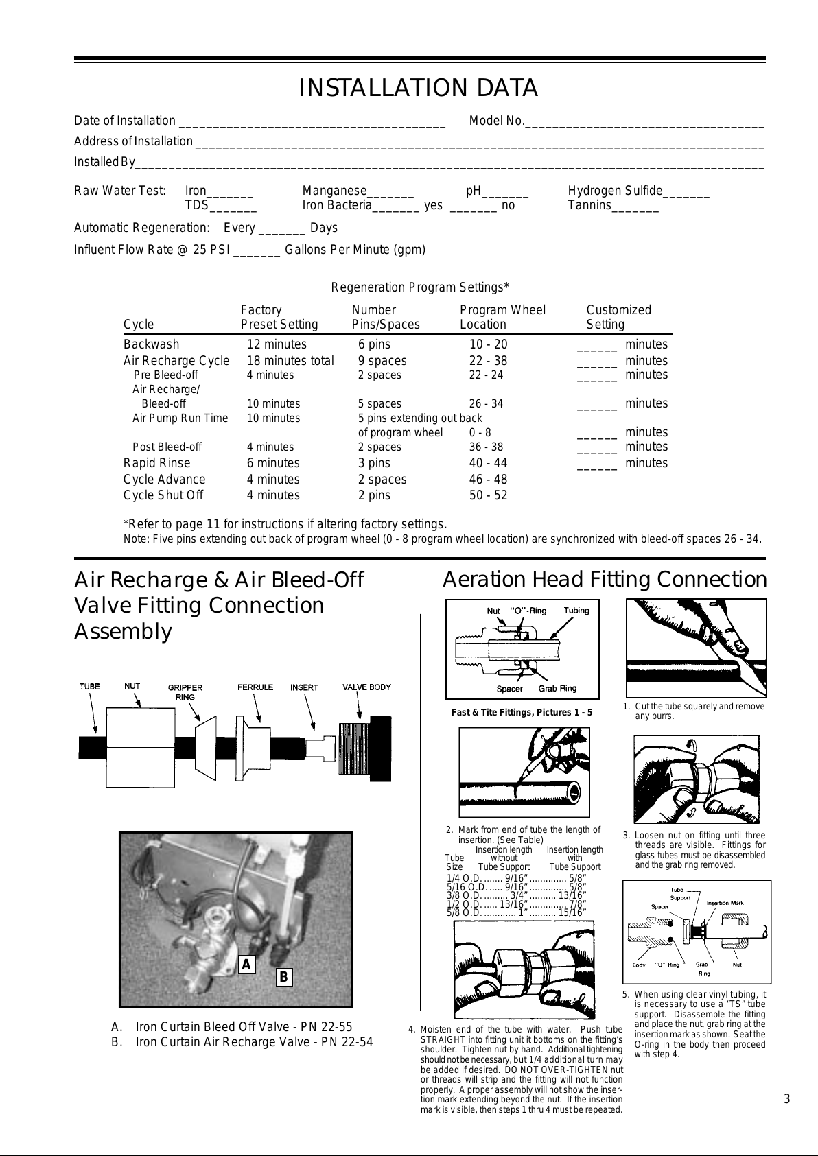
Fast & Tite Fittings, Pictures 1 - 5
Insertion length Insertion length
Tube without with
Size Tube Support Tube Support
2. Mark from end of tube the length of
insertion. (See Table)
1/4 O.D........ 9/16” .............. 5/8”
5/16 O.D...... 9/16” .............. 5/8”
3/8 O.D.......... 3/4” .......... 13/16”
1/2 O.D...... 13/16” .............. 7/8”
5/8 O.D............. 1” .......... 15/16”
4. Moisten end of the tube with water. Push tube
STRAIGHT into fitting unit it bottoms on the fitting’s
shoulder. Tighten nut by hand. Additional tightening
should not be necessary, but 1/4 additional turn may
be added if desired. DO NOT OVER-TIGHTEN nut
or threads will strip and the fitting will not function
properly. A proper assembly will not show the inser-
tion mark extending beyond the nut. If the insertion
mark is visible, then steps 1 thru 4 must be repeated.
1. Cut the tube squarely and remove
any burrs.
5. When using clear vinyl tubing, it
is necessary to use a “TS” tube
support. Disassemble the fitting
and place the nut, grab ring at the
insertion mark as shown. Seat the
O-ring in the body then proceed
with step 4.
Air Recharge & Air Bleed-Off
Valve Fitting Connection
Assembly
Aeration Head Fitting Connection
A
B
A. Iron Curtain Bleed Off Valve - PN 22-55
B. Iron Curtain Air Recharge Valve - PN 22-54
3. Loosen nut on fitting until three
threads are visible. Fittings for
glass tubes must be disassembled
and the grab ring removed.
All manuals and user guides at all-guides.com
Page 4
4
IRON CURTAIN
the way to solve this problem is to use layers of media.”
The advantages of a multi-media bed are:
1. Longer runs between backwash times.
2. Caking of the bed and breakthrough of turbidity are
virtually eliminated.
3. Much higher service flow rates per square foot.
4. Higher degree of clarity because of the heavier, finer filter
media in the bottom.
The standard Iron Curtain System uses five layers of filter
media. The top layer is made up of large, lighter weight
particles. The second layer contains a slightly heavier media.
The third layer contains a much heavier media.The fourth
layer contains an even heavier media. The fifth layer is a
special support bed to retain filter media so it does not pass
through the distribution system, and allows an even distrib-
uted flow of backwash water.
Operation of Aeration Pump
The Iron Curtain System introduces air into the aeration tank
and bleeds off the old head of air automatically. Following the
backwash cycle, both the air recharge valve and the air bleed
off valve open, allowing water and/or air to bleed out of the
aeration tank. After approximately 4 minutes, the aeration
pump automatically starts pumping a fresh head of air into the
aeration tank for approximately 10 minutes. After the pump
shuts off, the air recharge and air bleed off valves remain
open for an additional 4 minutes to allow any excess air and/
or water to bleed off to drain.
Advantages Over
Other Systems
1. Tested and validated by WQA under their S-200 Stan-
dard.
2. Uses no chemicals or salt.
3. Eliminates need for air injectors, venturis, or micronizers.
4. No floats or air volume controls to regulate air volume in
aeration tank which “foul” from iron.
5. Two-tank system consisting of a pressurized aeration
tank and multi-media depth filter.
6. 110V aeration pump to recharge aeration tank.
7. Can be used on shared wells, municipal water supplies,
or with buried pressure tanks without additional equip-
ment.
8. Higher service flow rates.
9. Better filtration results.
10. U.S. Patent #B1 5,096,596
Iron Filtration System
Aeration/precipitation/multi-media filtration for:
1. Iron Reduction/Removal
2. Manganese Reduction/Removal
3. Hydrogen Sulfide Reduction/Removal
A special Type A filter also provides pH adjustment on water
supplies with a pH from 6.0 or greater.
Principle of Operation
The Iron Curtain System uses a three step process of
oxidation, precipitation, and mechanical filtration for the
reduction/removal of iron, manganese, and hydrogen sul-
fide. The process of how the Iron Curtain System does each
one of these separate procedures is the key to the successful
results this product has obtained in the market place. There
are three main components that make up the Iron Curtain
System. They are:
1. IC Control Center w/Aeration Pump
2. Aeration Tank
3. Multi-Media Depth Filter
1
The first step in any oxidizing process is to bring the
raw water into intimate contact with a strong oxi-
dant. This will begin to convert the dissolved element such as
iron or manganese to a physical particle or nonsoluble
precipitate. The least expensive environmentally-safe oxi-
dant is oxygen (02)–air. To do this, the Iron Curtain System
makes the water spray through a regulated head of air in the
aeration tank.
2
The second step in this three step process of oxida-
tion - precipitation - filtration is to provide adequate
reaction or contact time for the precipitation to go to
completion. This allows time for the iron and/or manganese
particles to become large enough to filter out. The aeration
tank with the Iron Curtain System allows for several minutes
of contact time at the rated service flows, compared to only
seconds on other systems.
It should be noted that this reaction time will also be affected
by temperature; the warmer the water the faster the reaction.
This reaction time may also be affected by the presence of
organic material (such as tannins).
If tannins are present,
field tests have shown that they will not be removed and will
also hinder the ability of this system to effectively remove
iron, manganese, and/or hydrogen sulfide. Installation of this
system on water supplies with more than 0.5 ppm of tannins
will void warranty.
3
The third and final step is the removal of the precipi-
tates from the water. The WQA Water Filtration Study
Guide states:
“The ideal filter bed would be one with large grains at the top
to prevent the formation of a surface cake and to provide
large pores for course particles and small grains at the
bottom to entrap smaller particles. This allows the entire
depth of the bed to be used as a filter. This also allows for
longer filter runs and faster flow rates. Unfortunately, such an
ideal bed, when consisting of a single media is not possible,
All manuals and user guides at all-guides.com
Page 5
5
Operating Conditions
The Iron Curtain System has been validated by the WQA
under their S-200 Filter Standard for the reduction/removal of
iron, manganese, and/or hydrogen sulfide. The concentration
limits listed below reflect the maximum individual limit that
each contaminant was tested for separately without any
interference of other contaminants in the influent water.
In reality, however, we know that these contaminants may be
present in combination which may limit the filter’s ability to
remove these contaminants in higher concentrations. In
some cases, individual sellers of this equipment have had
success removing higher concentrations of contaminants—
iron, for example—above the limitations we have listed. If you
are considering the installation of this system for the reduc-
tion/removal of iron, manganese and/or hydrogen sulfide
beyond the printed operating conditions below, we recommend
that you consult the manufacturer for proper application.
Installation of this system under these circumstances may
void part(s) and/or all of the system warranty.
pH — The pH level of the influent water must be 7.0 or higher unless
you have a Type A filter, which will work on a pH of 6.0 to 7.0.
Iron — This system is rated for a maximum of 10 ppm of
ferrous (clear water) and/or ferric (red water) iron.*
Iron Bacteria — If iron bacteria are present; more frequent
service may result, the life of the Iron Curtain system may be
limited and the system may be unable to properly remove
iron. By properly controlling the iron bacteria with chlo-
rine or other approved methods for bacterial reduction,
the Iron Curtain System will function properly. One
option is to control iron bacteria within the Iron Curtain
is chlorine injection during the regeneration cycle. In
some instances, continuous chlorinaton of the water
supply may be needed.
Hydrogen Sulfide — Often referred to as rotten egg odor,
hydrogen sulfide will be reduced significantly on water supplies
containing less than 10 ppm. Past installations have shown
that hydrogen sulfide levels from 2.0 - 10.00 ppm will require
use of the Iron Curtain Remote Control Center and/or larger
aeration assembly. The Iron Curtain Remote Control Center
has an independent timer program which recharges the aeration
assembly with fresh oxygen up to six times per day, with the
filter(s) being regenerated with their own independent timer.*
Manganese — Limit 2.0 ppm; amounts present over 2.0 ppm
will gradually prevent iron removal. If manganese is present,
a larger filter should be installed with more frequent
backwashing. Note: For optimum manganese reduction, pH
should be greater than 8.5.*
Organic Matter (Tannins) — The presence of organic
matter such as tannins may tie up iron or manganese prevent-
ing the oxidation/filtration process from occuring.
The pres-
ence of organics such as tannins above 0.5 ppm voids any
claims for this system to perform as stated above. In some
applications, tannin levels below 0.5 ppm or the presence of
other organics may hinder the operation of this system.
Chlorine — The presence of chlorine in the raw water supply
ahead of this system should be limited to a maximum of 1.0
ppm residual and preferably 0.5 ppm or less when fed
continuously.
Total Dissolved Solids (TDS) — While TDS does not
directly affect iron removal, it is a good indicator of potential
interference. Most waters have TDS less than 500 and gener-
ally present no problems to iron treatment. If any ion becomes
excessive, it can possibly cause failure of iron removal.
A
TDS more than 750 ppm voids any claims for this system to
perform as stated above.*
General Application
Guidelines for Residential
Iron Curtain Systems
Iron Applications
0.3 - 3.0 ppm Iron Standard IC System, sized for
application service flow rate,
set to regenerate every three days.
3.0 - 6.0 ppm Iron Standard IC System, sized for
application service flow rate,
set to regenerate every other day.
6.0 - 10.0 ppm Iron Standard IC System, sized for
application service flow rate,
set to regenerate every day.
10+ ppm Iron Consult Factory
Note: Manganese will also be reduced if the pH of the
water is 8.5 or greater.
Hydrogen Sulfide Applications
Hydrogen Sulfide (H2S) consumes 7 times the amount of
oxygen to oxidize than iron does. Therefore, for Hydrogen
Sulfide Applications, we use the following guidelines:
0 - 1 ppm H2S Standard IC System, Aeration tank
sized for 2 minutes contact time.
2 - 4 ppm H2S IC System using Remote Control
Center with Pump, Aeration tank
sized for 2 minutes contact time.
Standard IC System could be used
for these applications, however the
system must be set to regenerate
every day to replenish air in
aeration tank. During high usage
times, available oxygen in the
aeration tank could be consumed,
allowing bleed through of H2S. By
using the Remote Control Center
with Pump, the air in aeration tank is
replenished every 4 hours and
filter(s) can be set to regenerate
everyday, every other day or every
three days.
5 - 8 ppm H2S IC System using Remote Control
Center with Pump, Aeration tank
sized for 3 minutes contact time.
Use an Iron Curtain Plus bed for
optimum results.
8-10 ppm H2S IC system using Remote Control
Center with Pump, Aeration tank
sized for a minimum of three
minutes contact time, Iron Curtain
Plus bed.
Also note that with TDS over 750 ppm, additional contact
time is recommended. Consult Factory.
*For application parameters outside the specified operating conditions or additional information regarding the listed items
contact your dealer.
All manuals and user guides at all-guides.com
Page 6
6
Caution: The water pressure is not to exceed 70 p.s.i.; water
temperature is not to exceed 110° F; conditioner cannot be
subject to freezing conditions; conditioner cannot be subject
to a negative pressure or vacuum. On installations where
there is the possibility of a negative pressure or vacuum, a
vacuum breaker or check valve must be installed at the inlet
of the conditioner. For example, if the water service is
interrupted due to a water pipe break, well pump being
serviced, etc., a back siphon could occur causing a vacuum
or negative pressure on the filtration equipment.
Installation Instructions
(See Page 3 for Special Factory Connections Assembly)
1. Follow all local and state plumbing and electrical codes.
2. A jumper ground wire should be installed where the metallic
continuity of a water distribution piping system is interrupted.
3. Turn the water supply off.
4. If you have a water softener, place the water softener on
bypass and close the shut-off valve to the water heater.
5. Drain down the plumbing system.
6. Mount the control valve and aeration pump on the filter tank.
7. Do all necessary plumbing as shown in Figures 1, 2 & 3
on page 8. If you want to filter outside hosebibbs, be sure
the filter system is properly sized to handle the flow rates
required for extended periods of time, in addition to the
normal household demand. Use a PVC compatible thread
sealer when connecting fittings to the aeration tank
manifold. Care must be taken not to overtighten
fittings into aeration tank manifold.
8. Run the drain line from the filter control in accordance with
local plumbing codes. The drain line will emit surges of
excess air from the aeration tank and therefore must be
secured. Models IC-10 & IC-10A have a 1/2” Male NPT
Drain Connection. Models IC-12 & IC-12A have a 3/4”
Female NPT Drain Connection. For all models, use a
minimum 3/4” I.D. Drain Line.
9. Connect the 3/8" white polytubing from the white fitting on the
aeration tank manifold to the air recharge valve on the Iron
Curtain Control Center. Connect the 3/8" black polytubing
from the black fitting on the aeration tank manifold to the air
bleedoff valve on the Iron Curtain Control Center. The 3/8"
white and black tubing are located in the Control Center
box. Cut tubing off to minimal necessary length after
aeration tank and filter tank are in place. Secure tubing
to the plumbing with cable ties provided. Connect drain
discharge line to pressure relief valve.
Start-Up
NOTE: The control valve is shipped in the air bleed off
position, see step #3 in flow diagrams, page 20.
1. Close all valves that were previously opened to drain the
plumbing system. Close the inlet and outlet valves on the
Iron Curtain Filter System and open the filter system
bypass valve. If you have a water softener, leave it on
bypass also.
2. Turn on the main water supply valve and flush the water
distribution system. Run water at the nearest cold water
faucet until all the air is relieved, lines are flushed and the
water is clear.
3. Open the inlet valve to the filter no more than 1/4 turn and
allow excess air in the filter tank to escape to drain. After
a steady stream of water is seen at the drain without any
air, proceed to the next step.
4. Close the bypass valve and open the inlet valve all the
way. Leave the outlet valve closed.
Pre-Installation
Check List
Water Pressure: A minimum of 30 psi at a predetermined
flow rate is required to backwash the filter properly, with a
maximum of 70 psi to be used.*
Actual Influent Flow Rate: (Water available from well
pump, service inlet, etc.) The actual pumping rate must
exceed the backwash rate for the model of filter selected at
a minimum of 30 psi. See actual backwash rates in the
Specifications section on page 7.
Electrical Requirements for Filter Control: A continuous
110 volts is required to cycle the controls and aeration pump.
Make certain the electrical supply is always on and cannot be
turned off with another switch.
Existing Plumbing: The condition of the existing plumbing
should be free from lime and iron build-up. Piping that is
heavily built-up with lime and/or iron should be replaced.
Equipment Location: See Figures 1, 2 & 3 on page 8&9.
Location of Aeration and Filter Tank: See Figures 1, 2 &
3 on page 8&9. These two tanks should be installed after the
pressure tank and as close to each other as practical. If you
want to filter outside hosebibbs, be sure the filter system is
properly sized to handle the flow rates required for extended
periods of time, in addition to the normal household demand.
Drain Lines: All drain lines must be a minimum of 3/4" or
equal to the size of the drain line connection at the control
valve or larger. Avoid overhead drain lines when possible. If
used, overhead drain lines are not to exceed a height of five
feet above the control valve and should be no more than fifty
feet in length.
Pressure Relief Valve: A pressure relief valve is installed in
the aeration tank manifold and it is recommended that a
separate drain line be extended toward the floor or to a drain
recepticle. NOTE: Do not plumb to a common drain line with
filter backwash discharge.
Check Valve: On applications where there is a non-filtered
demand for water such as joint wells (where the filter system
is only installed in one of two or more homes), outside
hosebibbs, farms with outbuildings, yard hydrants, etc. a
spring loaded check valve is provided and must be installed
ahead of the aeration tank. See Figures 1, 2 & 3 on page 8&9.
It is recommended to install the check valve in a vertical
upflow position with a minimum 12" water column above the
check valve. This prevents air from escaping past the check
valve. If the check valve is installed in a horizontal position, and
there is a simultaneous demand for both non-filtered and
filtered water, the air head in the aeration tank may escape
backwards past the check valve into the non-filtered water line
and cause air spitting.
By-Pass Valves: Always provide for a three-valve bypass on
the filter system. See Figures 1, 2 & 3 on page 8&9.
Optional Filter Inlet Shut-Off: This valve allows for servicing
of the filter tank and/or filter control valve without draining the
aeration tank. See Figures 1, 2 & 3 on page 8&9.
Filtered Water: Normally, filtered water is furnished to all
household lines; however, outside faucets are typically left
on raw water. If filtered water is provided to outside faucets,
the filter system must be sized accordingly.
All manuals and user guides at all-guides.com
all-guides.com
Page 7
7
Instructions for Adding IC pH
Correction Media
See Figures 1, 2 & 3 on page 8..
1. Place Iron Curtain System on bypass. (Close inlet and
outlet valves and open bypass valve.)
2. Relieve pressure by manually advancing timer to back-
wash position (see page 10). Unplug control valve after
valve is shifted into backwash position and piston has
stopped moving. After pressure is relieved, proceed.
2A. If your type “A” Iron Curtain filter is equipped with an
optional “dome hole and bottom drain” proceed as fol-
lows otherwise advance to step three:
a. After pressure is relieved remove the dome
plug by turning counter clockwise. Open the
bottom drain and allow approximately 15 inches
of water to drain out.
b. Measure down through the dome hole to deter-
mine media level. The media level may be as low
as 1/2 of the total tank height or as high as 2/3 of
the total tank height.
c. Add pH correction media and fill to a maximum
level of 2/3 of the total tank height. Approximately
17-18 inches down from the top of the tank on an
IC-12 or IC-10 respectively.
d. Replace the dome hole plug being cautious not to
cross-thread. Check the o’ring seal to be sure it
is clean from foreign debris. Hand tighten only,
plus approximately 1/8 of a turn with a wrench.
Be careful not to overtighten causing damage to
the threads.
e. Proceed to step 11.
3. Remove the control valve from tank (see page 14).
Determine if plumbing is rigid and able to support the
weight of the control valve assembly.
If the plumbing is rigid and able to support the weight of
the control valve assembly:
• Remove the two adapter base screws and slide the tank
away from the control valve and plumbing so it is easier
to work on.
If the plumbing is unable to support the weight of the
control valve assembly:
• IC-10A: Loosen the union nuts on the inlet and outlet and
disconnect plumbing. Loosen the fitting nuts on back of
air recharge and air bleed-off valves and remove tubing.
Loosen the fitting nut on drain line flow control housing
and remove tubing. Loosen the screw holding the drain
line flow control and disconnect the drain. Slide the tank
unit away from the plumbing so it is easier to work on.
• IC-12A: There must be a union installed on the inlet,
outlet, and drain line of control valve to proceed. If not,
they must be installed prior to proceeding. Loosen
the union on the inlet, outlet, and drain and disconnect
plumbing. Loosen the fitting nuts on back of air recharge
and air bleed-off valves and remove tubing. Slide the unit
away from the plumbing so it is easier to work on.
Remove the two adapter base screws and remove the
control valve assembly from the tank.
4. Remove the adapter base. Place the two adapter base
screws back in the adapter base and thread in until they
are flush with the bottom of the adapter base but not
touching the top of the tank. Carefully place a pry bar
5. Plug in the electrical cord from the Iron Curtain Control
Center. In approximately four minutes, the aeration
pump will automatically turn on and begin to pump air
into the aeration tank. Allow the Iron Curtain Control
Center to finish the remaining cycles automatically
(approximately 25 minutes). Make certain that the
filter control is in the Service Position (piston all the
way out). Do NOT backwash filter at this time. Set time
of day. Time of regeneration is preset for 12:00 a.m.
Regeneration frequency is preset for every three days.
(Type A Filters are preset for every other day.) If you
wish to reset any of these factory settings, see page 9.
6. Make sure the filter will not regenerate within 24
hours of installation to allow the filter media to
absorb water and not be backwashed out.
7. Open the outlet valve on the filter, then open the nearest
cold water faucet and allow the water to run until the air
stops spurting and discoloration is gone. Note: It is
normal for aerated water to appear effervescent.
8. If the water softener was placed on bypass, close the
bypass valve and place the softener in service.
9. Open the shut off valve to the water heater.
Regeneration Frequency
Your Iron Curtain Filter System contains a special filter media
mixture which allows it to filter iron longer than standard filters
between backwash regenerations. However, it is our recom-
mendation to leave factory settings as is, unless you wish to
backwash more frequently. You will have to backwash more
frequently if you have iron bacteria, hydrogen sulfide, and/or
manganese present in your water supply. You will also have
to regenerate more frequently if you notice iron bleed through
before the end of the normal service run.
Specifications
When supply water has a pH between 6.0 and 6.9, a Type A
filter system with sacrificial media is generally used. To
insure top performance this media needs to be replenished
periodically depending on water characteristics and usage
patterns, generally every 6 to 18 months. This can be
determined by testing the pH of the water at a cold filtered tap
or by physically measuring the amount of freeboard (See
Figure 8, page 4.) If the pH is 7.0 or greater, media does not
need to be added. If the pH is below 7.0 and/or the amount
of freeboard is greater than 18" for IC-10A or 17" for IC-12A
(see step 5), media needs to be added. If media needs to be
added contact your dealer and ask for the following:
Part Number 1-A8011
.66 cubic foot IC pH Correction Media (50 lb. bag)
TYPE A IRON CURTAIN
SYSTEMS (Optional)
IC-10 10"x54" 1.5 3/4" 5.0 5.0 26"x70"x16"
IC-10A 10"x54" 1.5 3/4" 5.0 5.0 26"x70"x16"
IC-10+ 10"x54" 1.5 3/4" 5.0 5.0 26"x70"x16
IC-12 12"x52" 2.0 1" 7.0 8.0 30"x68"x18"
IC-12A 12"x52" 2.0 1" 7.0 8.0 30"x68"x18"
IC-12+ 12"x52" 2.0 1" 7.0 8.0 30"x68"X18"
Model
Filter &
Aeration
Tank
Size
Floor
Space
(WxHxD)
(2) Back-
wash
Rate
GPM
Max.
Service
Flow
GPM
(1)
Inlet/
Outlet
Media
Cu. Ft
(1) Aeration Head and Check Valve have 1” Inlet/Outlet.
(2) Water temps above 60° F will require a higher backwash rate. Consult factory.
All manuals and user guides at all-guides.com
Page 8
8
Due to existing plumbing conditions, you may want to choose an alternate installation configuration.
Refer to Figures 2 and 3 below for alternate installation diagrams.
FIGURE 1
Carefully place a pry bar (long screwdriver, wrench, etc.)
between the screws and apply pressure clockwise until
tight. Be careful not to crease or tear the o-rings in the
adapter base. Remove the two screws from adapter base.
10. Reattach the control valve to the tank.
If the control valve was supported and connected to the
plumbing, slide the tank underneath the control valve and
align. Be careful not to dislodge or cut o-rings. Install
the two adapter base screws and tighten.
If the control valve was disconnected from plumbing,
place control valve on adapter base and align. Be care-
ful not to dislodge or cut o-rings. Install the two
adapter base screws and tighten.
• IC-10A: Reconnect the drain and tighten the screw
that holds the flow control housing. Reconnect the
bleed-off tubing to flow control housing and tighten
the fitting nut. Reconnect the tubing to the air
recharge and air bleed-off valves and tighten fitting
nuts. Reconnect inlet and outlet plumbing and
tighten the union nuts on inlet and outlet.
• IC-12A: Reconnect the tubing to the air recharge
and air bleed-off valves and tighten fitting nuts.
Reconnect inlet, outlet, and drain plumbing and
tighten unions.
11. Slowly open the inlet valve and allow filter to fill at a slow
rate. After a steady stream of water is running to drain,
completely open inlet valve. Open outlet valve and close
bypass valve.
12. Plug the control valve in and reset time of day (see page 9.)
13. Allow the system to finish the regeneration cycle and
return to service.
(long screwdriver, wrench, etc.) between the screws and
apply pressure counterclockwise to loosen the adapter
base. Be careful not to crease or tear the o-rings in
the adapter base. Unscrew the adapter base from tank
and remove. Be careful not to pull up the distributor
tube with adapter base. If distributor tube does pull
up with the adapter base, consult your dealer. At this
point, it is recommended to remove some of the water
from the tank. This can be done by placing a small hose
inside the distributor tube and creating a siphon; or by
carefully tipping the tank sideways, pouring out water
only, not media.
5. From the top of the tank, measure down approximately
1/3 the overall height of the tank (18" for IC-10A, 17" for
IC-12A) and mark the tank. This is the amount of free-
board and the maximum fill height that should not be
exceeded when adding media. If media is at correct
height and pH is below 7.0, do not add. Consult your
dealer.
6. Cover the distributor tube (use a plastic cap, or masking/
duct tape) so media will not get into the distributor tube.
7. Using a funnel, add IC pH correction media until it
reaches the maximum fill line.
8. Rinse the powdery fines from the funnel, covered dis-
tributor tube, and tank threads. Remove the funnel and
uncover distributor tube.
9. Place the adapter base back on tank and thread into
place until snug. Be careful not to cross thread the
adapter base in tank threads. You may need to "back
thread" the adapter base to get it started correctly.
PRESSURE
TANK
TO OUTSIDE
HOSEBIBBS
OUTLET
SHUT-OFF
THREE-VALVE
BY-PASS
INLET
SHUT-OFF
OPTIONAL
FILTER
INLET
SHUT-OFF
CHECK
VALVE
AIR-IN
AIR-OUT
PRESSURE
RELIEF VALVE
IRON
CURTAIN
AERATION
ASSEMBLY
IRON
CURTAIN
FILTER
DRAIN
LINE
FILTERED UNSOFTENED
WATER TO KITCHEN SINK
FILTERED WATER
TO WATER SOFTENER
All manuals and user guides at all-guides.com
Page 9
9
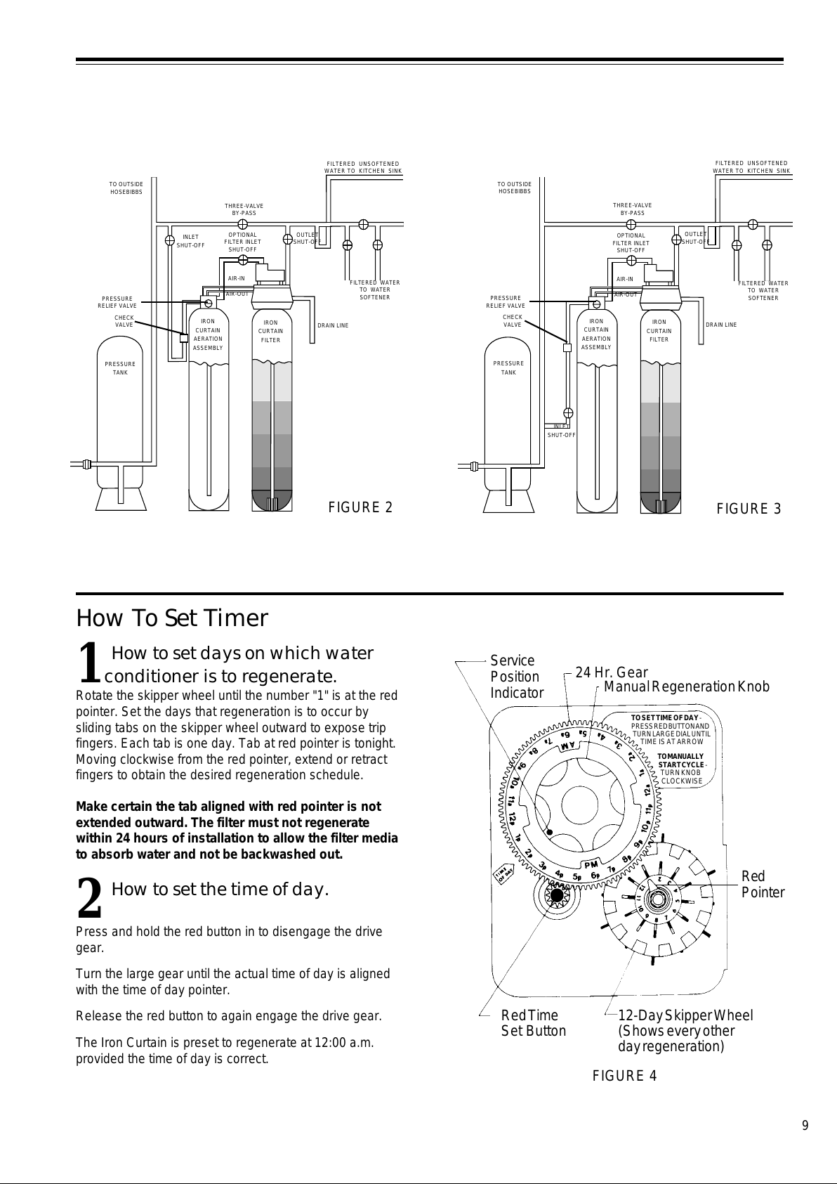
How To Set Timer
1
How to set days on which water
conditioner is to regenerate.
Rotate the skipper wheel until the number "1" is at the red
pointer. Set the days that regeneration is to occur by
sliding tabs on the skipper wheel outward to expose trip
fingers. Each tab is one day. Tab at red pointer is tonight.
Moving clockwise from the red pointer, extend or retract
fingers to obtain the desired regeneration schedule.
Make certain the tab aligned with red pointer is not
extended outward. The filter must not regenerate
within 24 hours of installation to allow the filter media
to absorb water and not be backwashed out.
2
How to set the time of day.
Press and hold the red button in to disengage the drive
gear.
Turn the large gear until the actual time of day is aligned
with the time of day pointer.
Release the red button to again engage the drive gear.
The Iron Curtain is preset to regenerate at 12:00 a.m.
provided the time of day is correct.
Service
Position
Indicator
24 Hr. Gear
Manual Regeneration Knob
TO SET TIME OF DAY -
PRESS RED BUTTON AND
TURN LARGE DIAL UNTIL
TIME IS AT ARROW
TO MANUALLY
START CYCLE -
TURN KNOB
CLO CKWI SE
12-Day Skipper Wheel
(Shows every other
day regeneration)
Red Time
Set Button
Red
Pointer
FIGURE 4
FIGURE 2
AIR-OUT
AIR-IN
PRESSURE
TANK
TO OUTSIDE
HOSEBIBBS
PRESSURE
RELIEF VALVE
IRON
CURTAIN
AERATION
ASSEMBLY
IRON
CURTAIN
FILTER
DRAIN LINE
OPTIONAL
FILTER INLET
SHUT-OFF
THREE-VALVE
BY-PASS
CHECK
VALVE
INLET
SHUT-OFF
OUTLET
SHUT-OFF
FILTERED WATER
TO WATER
SOFTENER
FILTERED UNSOFTENED
WATER TO KITCHEN SINK
FIGURE 3
PRESSURE
TANK
TO OUTSIDE
HOSEBIBBS
PRESSURE
RELIEF VALVE
IRON
CURTAIN
AERATION
ASSEMBLY
IRON
CURTAIN
FILTER
DRAIN LINE
THREE-VALVE
BY-PASS
CHECK
VALVE
OUTLET
SHUT-OFF
FILTERED UNSOFTENED
WATER TO KITCHEN SINK
INLET
SHUT-OFF
AIR-OUT
FILTERED WATER
TO WATER
SOFTENER
OPTIONAL
FILTER INLET
SHUT-OFF
AIR-IN
All manuals and user guides at all-guides.com
Page 10
10
How To Manually Regenerate
Your Water Filter At Any Time
Slowly turn the manual regeneration knob clockwise until the
drive motor starts running.
The movement of the manual regeneration knob engages
the program wheel and starts the regeneration program.
The black center knob will make one revolution in
approximately the following three hours and stop in the
service position as shown in the drawing.
Even though it takes three hours for this center knob to
complete one revolution, the regeneration cycle of your unit
is generally set for only one third of this time.
In any event, conditioned water may be drawn after rinse
water stops flowing from the water conditioner drain line.
How To Manually Advance
Control Center to a Specific Cycle
(See Figure 5 on page 11 for location of specific cycles.)
To manually advance the Iron Curtain Control Center to a
specific cycle, you must start with unit in the service position
(service position indicator aligned with time of day arrow as
shown in Figure 4, Page 9). Advance the timer from one cycle
to the next, pausing between each cycle until the drive motor
stops running. If you do not wait until the drive motor stops
running, the timer and the drive motor will become out of
synch. If that happens, advance the timer to the service
position and the control valve piston will return also to the
service position. They are now resynchronized.
The first cycle is the
backwash
cycle: Slowly turn manual
regeneration knob clockwise until backwash pins engage
microswitch arm and drive motor begins running. Wait until
drive motor stops before proceeding to next cycle.
The second cycle is the
air recharge
cycle: Slowly turn the
manual regeneration knob clockwise until backwash pins
drop off microswitch arm and drive motor begins running.
Wait until drive motor stops before proceeding to next cycle.
The third cycle is the
rapid rinse
cycle: Slowly turn the manual
regeneration knob clockwise until rapid rinse pins engage
microswitch arm and drive motor begins running. Wait until
drive motor stops before proceeding to next cycle.
The fourth cycle is the
cycle advance
cycle: Slowly turn the
manual regeneration knob clockwise until rapid rinse pins
drop off microswitch arm and drive motor begins running.
Wait until drive motor stops before proceeding to next cycle.
The final cycle is the
cycle shut off
cycle: Slowly turn the
manual regeneration knob clockwise until cycle shut off pins
engage microswitch arm and drive motor begins running.
Wait until drive motor stops before advancing the timer to
service position.
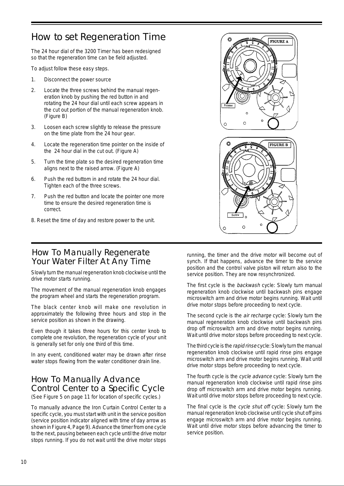
The 24 hour dial of the 3200 Timer has been redesigned
so that the regeneration time can be field adjusted.
To adjust follow these easy steps.
1. Disconnect the power source
2. Locate the three screws behind the manual regen-
eration knob by pushing the red button in and
rotating the 24 hour dial until each screw appears in
the cut out portion of the manual regeneration knob.
(Figure B)
3. Loosen each screw slightly to release the pressure
on the time plate from the 24 hour gear.
4. Locate the regeneration time pointer on the inside of
the 24 hour dial in the cut out. (Figure A)
5. Turn the time plate so the desired regeneration time
aligns next to the raised arrow. (Figure A)
6. Push the red buttom in and rotate the 24 hour dial.
Tighten each of the three screws.
7. Push the red button and locate the pointer one more
time to ensure the desired regeneration time is
correct.
8. Reset the time of day and restore power to the unit.
How to set Regeneration Time
All manuals and user guides at all-guides.com
Page 11
11
How To Set Regeneration Cycle Program
1
How to set the regeneration
cycle program.
The regeneration cycle program on your Iron Curtain Filter
has been factory preset, however, portions of the cycle
or
program may be lengthened or shortened to suit local
conditions.
To expose cycle program wheel, grasp timer in upper left-
hand corner and pull, releasing snap retainer, and swing
timer to the right.
To change the regeneration cycle program, the program
wheel must be removed. Make sure the timer is in the service
position and then unplug the power cord. Grasp program
wheel and squeeze protruding lugs toward center of wheel.
Lift program wheel off timer. (The arm on the program
actuator switch may need to be moved to facilitate removal.)
After making the necessary adjustments described in steps
2, 3, and 4, install the program wheel on the timer. Place
program wheel over the protruding lugs and gently push
program wheel on until the tabs on the lugs are snapped in
place over the wheel. (The arm on the program actuator
switch may need to be moved to facilitate installation.)
Return timer to closed position engaging snap retainer in
back plate. Make certain all electrical wires are located above
snap retainer post. Plug in power cord.
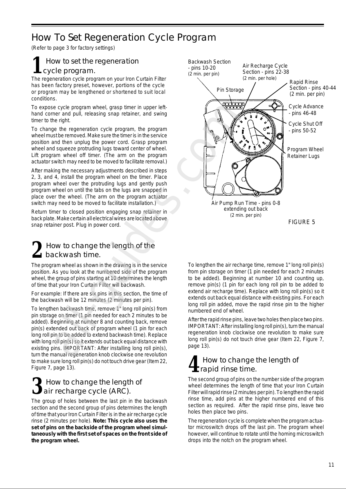
The program wheel as shown in the drawing is in the service
position. As you look at the numbered side of the program
wheel, the group of pins starting at 10 determines the length
of time that your Iron Curtain Filter will backwash.
For example: If there are six pins in this section, the time of
the backwash will be 12 minutes (2 minutes per pin).
To lengthen backwash time, remove 1" long roll pin(s) from
pin storage on timer (1 pin needed for each 2 minutes to be
added). Beginning at number 8 and counting back, remove
pin(s) extended out back of program wheel (1 pin for each
long roll pin to be added to extend backwash time). Replace
with long roll pin(s) so it extends out back equal distance with
existing pins. IMPORTANT: After installing long roll pin(s),
turn the manual regeneration knob clockwise one revolution
to make sure long roll pin(s) do not touch drive gear (Item 22,
Figure 7, page 13).
3
How to change the length of
air recharge cycle (ARC).
The group of holes between the last pin in the backwash
section and the second group of pins determines the length
of time that your Iron Curtain Filter is in the air recharge cycle
rinse (2 minutes per hole). Note: This cycle also uses the
set of pins on the backside of the program wheel simul-
taneously with the first set of spaces on the front side of
the program wheel.
(Refer to page 3 for factory settings)
To lengthen the air recharge time, remove 1" long roll pin(s)
from pin storage on timer (1 pin needed for each 2 minutes
to be added). Beginning at number 10 and counting up,
remove pin(s) (1 pin for each long roll pin to be added to
extend air recharge time). Replace with long roll pin(s) so it
extends out back equal distance with existing pins. For each
long roll pin added, move the rapid rinse pin to the higher
numbered end of wheel.
After the rapid rinse pins, leave two holes then place two pins.
IMPORTANT: After installing long roll pin(s), turn the manual
regeneration knob clockwise one revolution to make sure
long roll pin(s) do not touch drive gear (Item 22, Figure 7,
page 13).
4
How to change the length of
rapid rinse time.
The second group of pins on the number side of the program
wheel determines the length of time that your Iron Curtain
Filter will rapid rinse (2 minutes per pin). To lengthen the rapid
rinse time, add pins at the higher numbered end of this
section as required. After the rapid rinse pins, leave two
holes then place two pins.
The regeneration cycle is complete when the program actua-
tor microswitch drops off the last pin. The program wheel
however, will continue to rotate until the homing microswitch
drops into the notch on the program wheel.
FIGURE 5
2
How to change the length of the
backwash time.
Pin Storage
Backwash Section
- pins 10-20
(2 min. per pin)
Air Recharge Cycle
Section - pins 22-38
(2 min. per hole)
Rapid Rinse
Section - pins 40-44
(2 min. per pin)
Cycle Advance
- pins 46-48
Cycle Shut Off
- pins 50-52
Air Pump Run Time - pins 0-8
extending out back
(2 min. per pin)
Program Wheel
Retainer Lugs
All manuals and user guides at all-guides.com
all-guides.com
Page 12
12
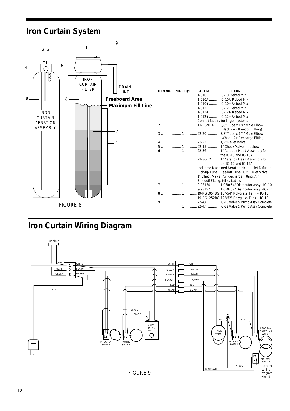
Iron Curtain System
Iron Curtain Wiring Diagram
1
2
3
WHITE
BLK/WHT
GREEN
GREEN
BLACK
WH
WHITE
BLK/WHT
BROWN
YELLOW
RED
BLACK
WHITE
BLK/WHT
BROWN
YELLOW
RED
BLACK
BLACK
BLACK
BLACK
BLACK/WHITE
TIMER
MOTOR
PROGRAM
ACTUATOR
SWITCH
AIR PUMP
SWITCH
BLACK
BLACK
BLACK
PROGRAM
SWITCH
HOMING
SWITCH
VALVE
DRIVE
MOTOR
HOMING
SWITCH
TO
AIR PUMP
(Located
behind
program
wheel)
FIGURE 9
IRON
CURTAIN
FILTER
DRAIN
LINE
Freeboard Area
Maximum Fill Line
IRON
CURTAIN
AERATION
ASSEMBLY
1
6
2
4
3
FIGURE 8
8
8
7
ITEM NO. NO. REQ'D. PART NO. DESCRIPTION
1 ..................... 1.............1-010 ............. IC-10 Rebed Mix
1-010A........... IC-10A Rebed Mix
1-010+ ........... IC-10+ Rebed Mix
1-012 ............. IC-12 Rebed Mix
1-012A........... IC-12A Rebed Mix
1-012+ ........... IC-12+ Rebed Mix
Consult factory for larger systems
2 ..................... 1.............11-P6ME4 ..... 3/8" Tube x 1/4" Male Elbow
(Black - Air Bleedoff Fitting)
3 ..................... 1.............22-20 ............. 3/8" Tube x 1/4" Male Elbow
(White - Air Recharge Fitting)
4 ..................... 1.............22-22 ............. 1/2" Relief Valve
5 ..................... 1.............22-15 ............. 1" Check Valve (not shown)
6 1 22-36 1" Aeration Head Assembly for
the IC-10 and IC-10A
22-36-12 1" Aeration Head Assembly for
the IC-12 and IC-12A
Includes: Machined Aeration Head, Inlet Diffuser,
Pick-up Tube, Bleedoff Tube, 1/2" Relief Valve,
1" Check Valve, Air Recharge Fitting, Air
Bleedoff Fitting, Misc. Labels
7 ..................... 1.............9-93154 ......... 1.050x54" Distributor Assy.–IC-10
9-93152 ......... 1.050x52" Distributor Assy.–IC-12
8 ..................... 1.............19-PG1054BG 10"x54" Polyglass Tank – IC-10
19-PG1252BG 12"x52" Polyglass Tank – IC-12
9 ..................... 1.............22-43 .............. IC-10 Valve & Pump Assy Complete
1.............22-47 .............. IC-12 Valve & Pump Assy Complete
9
All manuals and user guides at all-guides.com
Page 13
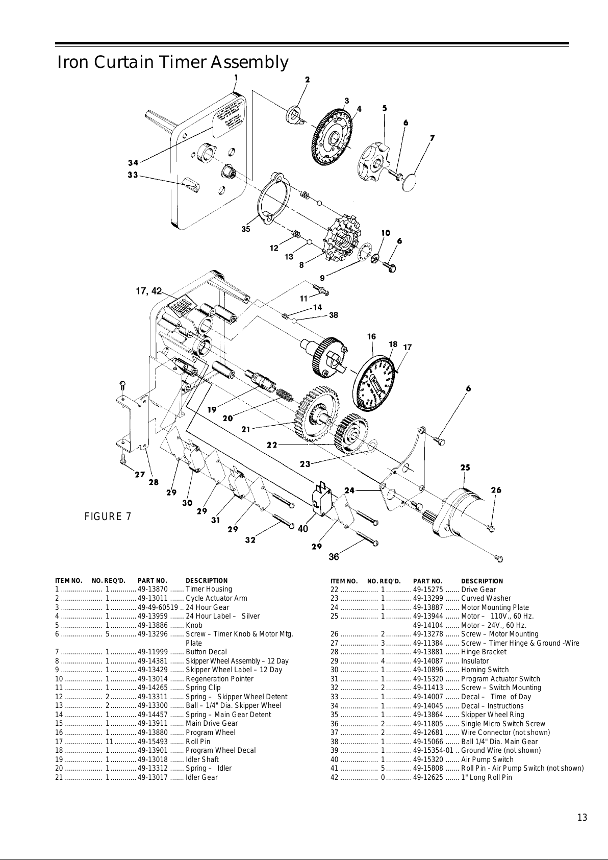
13
Iron Curtain Timer Assembly
ITEM NO. NO. REQ'D. PART NO. DESCRIPTION
1 ..................... 1.............49-13870 ....... Timer Housing
2 ..................... 1.............49-13011 ....... Cycle Actuator Arm
3 ..................... 1.............49-49-60519 .. 24 Hour Gear
4 ..................... 1.............49-13959 ....... 24 Hour Label – Silver
5 ..................... 1.............49-13886 ....... Knob
6 ..................... 5.............49-13296 ....... Screw – Timer Knob & Motor Mtg.
Plate
7 ..................... 1.............49-11999 ....... Button Decal
8 ..................... 1.............49-14381 ....... Skipper Wheel Assembly – 12 Day
9 ..................... 1.............49-13429 ....... Skipper Wheel Label – 12 Day
10 ................... 1.............49-13014 ....... Regeneration Pointer
11 ................... 1.............49-14265 ....... Spring Clip
12 ................... 2.............49-13311 ....... Spring – Skipper Wheel Detent
13 ................... 2.............49-13300 ....... Ball – 1/4" Dia. Skipper Wheel
14 ................... 1.............49-14457 ....... Spring – Main Gear Detent
15 ................... 1.............49-13911 ....... Main Drive Gear
16 ................... 1.............49-13880 ....... Program Wheel
17 ................... 11...........49-15493 ....... Roll Pin
18 ................... 1.............49-13901 ....... Program Wheel Decal
19 ................... 1.............49-13018 ....... Idler Shaft
20 ................... 1.............49-13312 ....... Spring – Idler
21 ................... 1.............49-13017 ....... Idler Gear
ITEM NO. NO. REQ'D. PART NO. DESCRIPTION
22 ................... 1.............49-15275 ....... Drive Gear
23 ................... 1.............49-13299 ....... Curved Washer
24 ................... 1.............49-13887 ....... Motor Mounting Plate
25 ................... 1.............49-13944 ....... Motor – 110V., 60 Hz.
49-14104 ....... Motor – 24V., 60 Hz.
26 ................... 2.............49-13278 ....... Screw – Motor Mounting
27 ................... 3.............49-11384 ....... Screw – Timer Hinge & Ground -Wire
28 ................... 1.............49-13881 ....... Hinge Bracket
29 ................... 4.............49-14087 ....... Insulator
30 ................... 1.............49-10896 ....... Homing Switch
31 ................... 1.............49-15320 ....... Program Actuator Switch
32 ................... 2.............49-11413 ....... Screw – Switch Mounting
33 ................... 1.............49-14007 ....... Decal – Time of Day
34 ................... 1.............49-14045 ....... Decal – Instructions
35 ................... 1.............49-13864 ....... Skipper Wheel Ring
36 ................... 2.............49-11805 ....... Single Micro Switch Screw
37 ................... 2.............49-12681 ....... Wire Connector (not shown)
38 ................... 1.............49-15066 ....... Ball 1/4" Dia. Main Gear
39 ................... 1.............49-15354-01 .. Ground Wire (not shown)
40 ................... 1.............49-15320 ....... Air Pump Switch
41 ................... 5.............49-15808 ....... Roll Pin - Air Pump Switch (not shown)
42 ................... 0.............49-12625 ....... 1" Long Roll Pin
FIGURE 7
All manuals and user guides at all-guides.com
Page 14
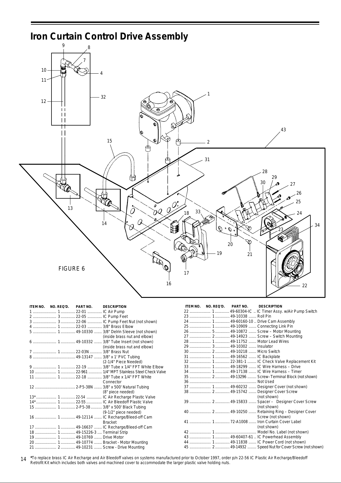
14
Iron Curtain Control Drive Assembly
32
10
7
9
11
12
8
4
13
14
1
2
31
33
17
16
18
19
28
30
29
26
25
24
21
20
27
34
23
15
ITEM NO. NO. REQ'D. PART NO. DESCRIPTION
1 ..................... 1.............22-01 ............. IC Air Pump
2 ..................... 3.............22-05 ............. IC Pump Feet
3 ..................... 3.............22-06 ............. IC Pump Feet Nut (not shown)
4 ..................... 1.............22-03 ............. 3/8" Brass Elbow
5 ..................... 1.............49-10330 ....... 3/8" Delrin Sleeve (not shown)
(inside brass nut and elbow)
6 ..................... 1.............49-10332 ....... 3/8" Tube Insert (not shown)
(inside brass nut and elbow)
7 ..................... 1.............22-03N ........... 3/8" Brass Nut
8 ......................................49-13147 ....... 3/8" x 1' PVC Tubing
(2-1/4" Piece Needed)
9 ..................... 1.............22-19 ............. 3/8" Tube x 1/4" FPT White Elbow
10 ................... 1.............22-961 ............ 1/4" MPT Stainless Steel Check Valve
11 ................... 1.............22-18 ............. 3/8" Tube x 1/4" FPT White
Connector
12 ....................................2-P5-38N ....... 3/8" x 500' Natural Tubing
(8" piece needed)
13*.................. 1.............
22-54 ...............
IC Air Recharge Plastic Valve
14*.................. 1............. 22-55 .............. IC Air Bleedoff Plastic Valve
15 ................... 1.............2-P5-38 .......... 3/8" x 500' Black Tubing
(9-1/2" piece needed)
16 ................... 1.............49-12114 ....... IC Recharge/Bleed-off Cam
Bracket
17 ................... 1.............49-16637 ....... IC Recharge/Bleed-off Cam
18 ................... 1.............49-15226-3 .... Terminal Strip
19 ................... 1.............49-10769 ....... Drive Motor
20 ................... 1.............49-10774 ....... Bracket - Motor Mounting
21 ................... 2.............49-10231 ....... Screw - Drive Mounting
ITEM NO. NO. REQ'D. PART NO. DESCRIPTION
22 ................... 1............. 49-60304-IC .. IC Timer Assy. w/Air Pump Switch
23 ................... 1.............49-10338 ....... Roll Pin
24 ................... 1.............49-60160-10 .. Drive Cam Assembly
25 ................... 1.............49-10909 ....... Connecting Link Pin
26 ................... 5.............49-10872 ....... Screw – Motor Mounting
27 ................... 2.............49-14923 ....... Screw – Switch Mounting
28 ................... 1.............49-11752 ....... Motor Lead Wires
29 ................... 3.............49-10302 ....... Insulator
30 ................... 2.............49-10218 ....... Micro Switch
31 ................... 1.............49-16562 ....... IC Backplate
32 ................... 1.............22-381-1 ........ IC Check Valve Replacement Kit
33 ................... 1.............49-18299 ....... IC Wire Harness – Drive
34 ................... 1.............49-17138 ....... IC Wire Harness – Timer
35 ................... 2.............49-13296 ........ Screw–Terminal Block (not shown)
36 ............................................................ Not Used
37 ................... 1.............49-60232 ....... Designer Cover (not shown)
38 ................... 2.............49-15742 ....... Designer Cover Screw
(not shown)
39 ................... 2.............49-15833 ....... Spacer – Designer Cover Screw
(not shown)
40 ................... 2.............49-10250 ....... Retaining Ring – Designer Cover
Screw (not shown)
41 ................... 1.............72-A1008 ....... Iron Curtain Cover Label
(not shown)
42 ................... 1..................................... Model No. Label (not shown)
43 ................... 1.............49-60407-61 .. IC Powerhead Assembly
44 ................... 1.............49-11838 ....... IC Power Cord (not shown)
45 ................... 2.............49-14932 ........ Speed Nut for Cover Screw (not shown)
22
FIGURE 6
43
*To replace brass IC Air Recharge and Air Bleedoff valves on systems manufactured prior to October 1997, order p/n 22-56 IC Plastic Air Recharge/Bleedoff
Retrofit Kit which includes both valves and machined cover to accommodate the larger plastic valve holding nuts.
All manuals and user guides at all-guides.com
Page 15
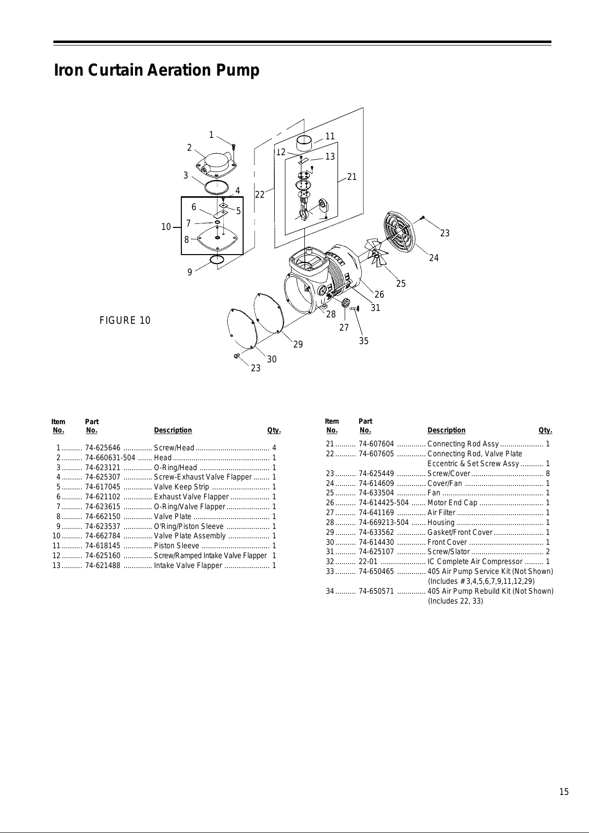
15
Iron Curtain Aeration Pump
Item Part
No. No. Description Qty.
1.......... 74-625646 .............. Screw/Head.................................... 4
2.......... 74-660631-504 .......Head ............................................... 1
3.......... 74-623121 .............. O-Ring/Head .................................. 1
4.......... 74-625307 .............. Screw-Exhaust Valve Flapper........ 1
5.......... 74-617045 .............. Valve Keep Strip ............................ 1
6.......... 74-621102 .............. Exhaust Valve Flapper ................... 1
7.......... 74-623615 .............. O-Ring/Valve Flapper..................... 1
8.......... 74-662150 .............. Valve Plate ..................................... 1
9.......... 74-623537 .............. O'Ring/Piston Sleeve ..................... 1
10.......... 74-662784 .............. Valve Plate Assembly .................... 1
11.......... 74-618145 .............. Piston Sleeve ................................. 1
12.......... 74-625160 .............. Screw/Ramped Intake Valve Flapper 1
13.......... 74-621488 .............. Intake Valve Flapper ...................... 1
FIGURE 10
Item Part
No. No. Description Qty.
21.......... 74-607604 .............. Connecting Rod Assy..................... 1
22.......... 74-607605 .............. Connecting Rod, Valve Plate
Eccentric & Set Screw Assy........... 1
23.......... 74-625449 .............. Screw/Cover................................... 8
24.......... 74-614609 .............. Cover/Fan ...................................... 1
25.......... 74-633504 .............. Fan ................................................. 1
26.......... 74-614425-504 .......Motor End Cap ............................... 1
27.......... 74-641169 .............. Air Filter .......................................... 1
28.......... 74-669213-504 .......Housing .......................................... 1
29.......... 74-633562 .............. Gasket/Front Cover ........................ 1
30.......... 74-614430 .............. Front Cover .................................... 1
31.......... 74-625107 .............. Screw/Slator ................................... 2
32.......... 22-01 ...................... IC Complete Air Compressor ......... 1
33.......... 74-650465 .............. 405 Air Pump Service Kit (Not Shown)
(Includes # 3,4,5,6,7,9,11,12,29)
34.......... 74-650571 .............. 405 Air Pump Rebuild Kit (Not Shown)
(Includes 22, 33)
21
1
2
3
9
6
10
23
30
29
28
27
22
12
26
31
25
24
23
11
13
4
7
8
5
35
All manuals and user guides at all-guides.com
Page 16
16
Iron Curtain Aeration Pump Repair Instructions
Air pump must be removed from tank and have power
supply disconnected before proceeding.
1. Remove four front cover screws and remove front
cover and cover gasket.
2. Remove four pump head screws and remove pump
head.
3. Remove valve plate assembly.
4. Remove felt air filter on side of pump with a flat screw
driver prying under the flat center retainer.
5. Remove piston sleeve from connecting rod assem-
bly.
6. Using an 1/8” allen wrench through the air intake hole
loosen eccentric/bearing and piston connecting rod
assembly set screw and remove eccentric/bearing
and connecting rod assembly.
7. If eccentric & bearing assembly need replacing: Us-
ing a 1/8 allen wrench through air intake hole, loosen
eccentric & bearing assembly screw and remove
eccentric & bearing assembly. Remove piston sleeve
from connecting rod assembly. Remove valve flap-
per screw and valve flapper. Remove intake valve
plate screws and remove ramped valve plate and
piston cup. Install new piston cup on connecting rod.
Place a dab of silicone caulk in the center dimple on
bottom side of ramped valve plate and install ramped
valve plate and intake valve plate screws (12” lbs.)
making sure the intake hole is aligned in the connecting
rod, piston cup and ramped valve plate. Install new
valve flapper and valve screw (12” lbs.). Slide new
piston sleeve upwards over connecting rod assembly
starting from the bottom, forcing new piston cup to
curve upwards inside piston sleeve. Note: If piston
sleeve slides over the top of connecting rod assem-
bly, reinstall, starting from the bottom.
8. If installing new connecting rod assembly, slide new
piston sleeve upwards over connecting rod assembly
starting from the bottom, forcing new piston cup to
curve upwards inside piston sleeve. Note: If piston
sleeve slides over top of connecting rod assembly,
reinstall, starting from the bottom.
9. From the top of the pump insert connecting rod/eccen-
tric bearing assembly with set screw facing air filter
holes. Install on motor shaft all the way and tighten set
screw (8” lbs.) Note: Set screw should tighten onto
flat spot on motor shaft.
10. Remove exhaust valve flapper screw, valve keeper
strip, valve flapper, valve flapper o-ring and piston
sleeve o-ring from valve plate. Lubricate new o-rings with
silicone lubricant to hold o-rings in place and install
in valve plate. Install new valve flapper, valve keeper
strip and exhaust valve flapper screw (12" lbs.) in
valve plate.
11. Install valve plate on pump, aligning piston sleeve o-
ring with top of piston sleeve.
12. Remove o-ring from pump head. Place 3-4 small dabs
of silicone lubricant in pump head o-ring groove to hold
o-ring in place and install o-ring in pump head.
13. Install pump head on pump, aligning exhaust port with
front of pump. Install four pump head screws and
tighten (48" lbs.).
14. Remove any remaining gasket material from front cover
and pump front and make sure both surfaces are clean.
15. Install new front cover gasket with burr side in. Install
front cover and four cover screws and tighten screws
(20" lbs.).
16. Air pumps manufactured after 11/94 use an air filter
with a hole in the center and a plastic press in
retainer to hold it in place. To replace air filter, order
p/n 74-641169 Air Filter and Retainer. Place air filter
in place and install new retainer.
All manuals and user guides at all-guides.com
all-guides.com
Page 17
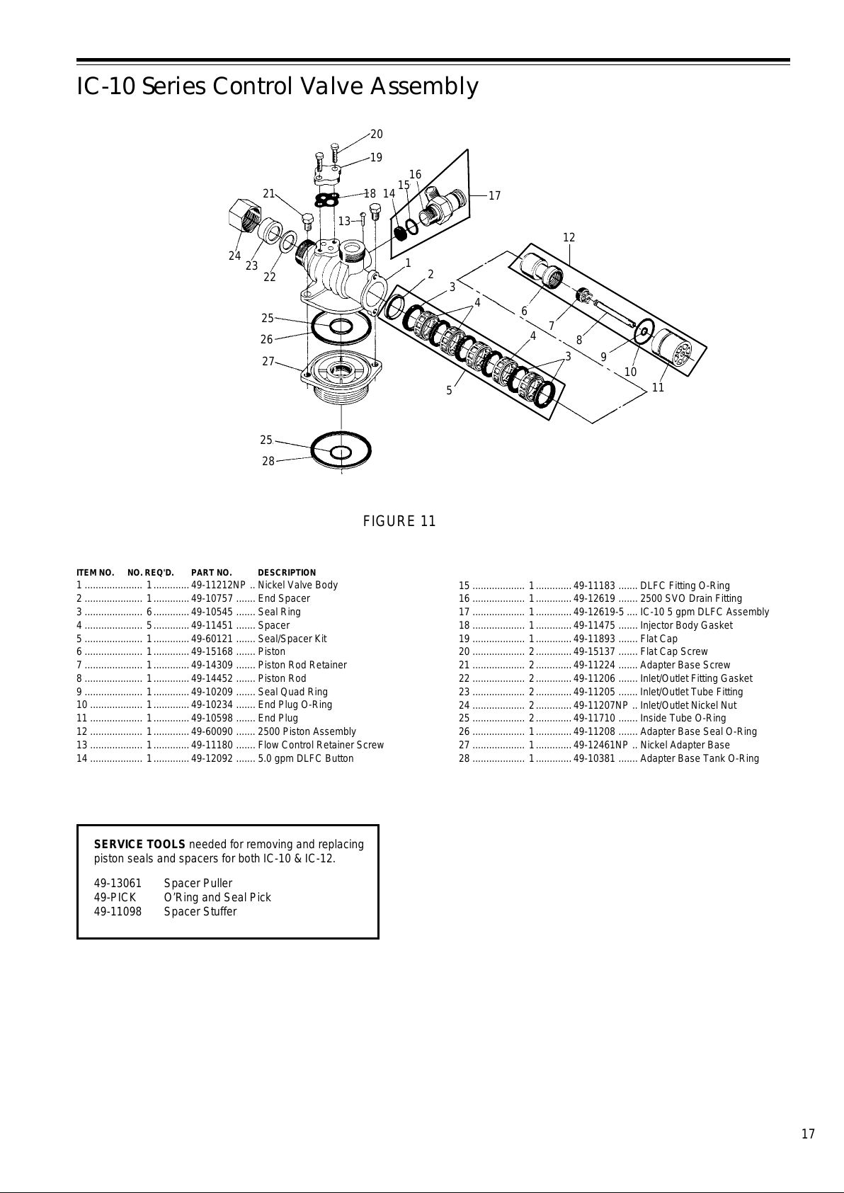
17
IC-10 Series Control Valve Assembly
ITEM NO. NO. REQ'D. PART NO. DESCRIPTION
1 ..................... 1.............49-11212NP .. Nickel Valve Body
2 ..................... 1.............49-10757 ....... End Spacer
3 ..................... 6.............49-10545 ....... Seal Ring
4 ..................... 5.............49-11451 ....... Spacer
5 ..................... 1.............49-60121 ....... Seal/Spacer Kit
6 ..................... 1.............49-15168 ....... Piston
7 ..................... 1.............49-14309 ....... Piston Rod Retainer
8 ..................... 1.............49-14452 ....... Piston Rod
9 ..................... 1.............49-10209 ....... Seal Quad Ring
10 ................... 1.............49-10234 ....... End Plug O-Ring
11 ................... 1.............49-10598 ....... End Plug
12 ................... 1.............49-60090 ....... 2500 Piston Assembly
13 ................... 1.............49-11180 ....... Flow Control Retainer Screw
14 ................... 1.............49-12092 ....... 5.0 gpm DLFC Button
5
17
12
FIGURE 11
16
26
25
22
23
24
21
9
10
11
8
7
6
3
4
4
3
2
1
15
14
25
28
27
13
18
20
19
15 ................... 1.............49-11183 ....... DLFC Fitting O-Ring
16 ................... 1.............49-12619 ....... 2500 SVO Drain Fitting
17 ................... 1.............49-12619-5 .... IC-10 5 gpm DLFC Assembly
18 ................... 1.............49-11475 ....... Injector Body Gasket
19 ................... 1.............49-11893 ....... Flat Cap
20 ................... 2.............49-15137 ....... Flat Cap Screw
21 ................... 2.............49-11224 ....... Adapter Base Screw
22 ................... 2.............49-11206 ....... Inlet/Outlet Fitting Gasket
23 ................... 2.............49-11205 ....... Inlet/Outlet Tube Fitting
24 ................... 2.............49-11207NP .. Inlet/Outlet Nickel Nut
25 ................... 2.............49-11710 ....... Inside Tube O-Ring
26 ................... 1.............49-11208 ....... Adapter Base Seal O-Ring
27 ................... 1.............49-12461NP .. Nickel Adapter Base
28 ................... 1.............49-10381 ....... Adapter Base Tank O-Ring
SERVICE TOOLS needed for removing and replacing
piston seals and spacers for both IC-10 & IC-12.
49-13061 Spacer Puller
49-PICK O’Ring and Seal Pick
49-11098 Spacer Stuffer
All manuals and user guides at all-guides.com
Page 18
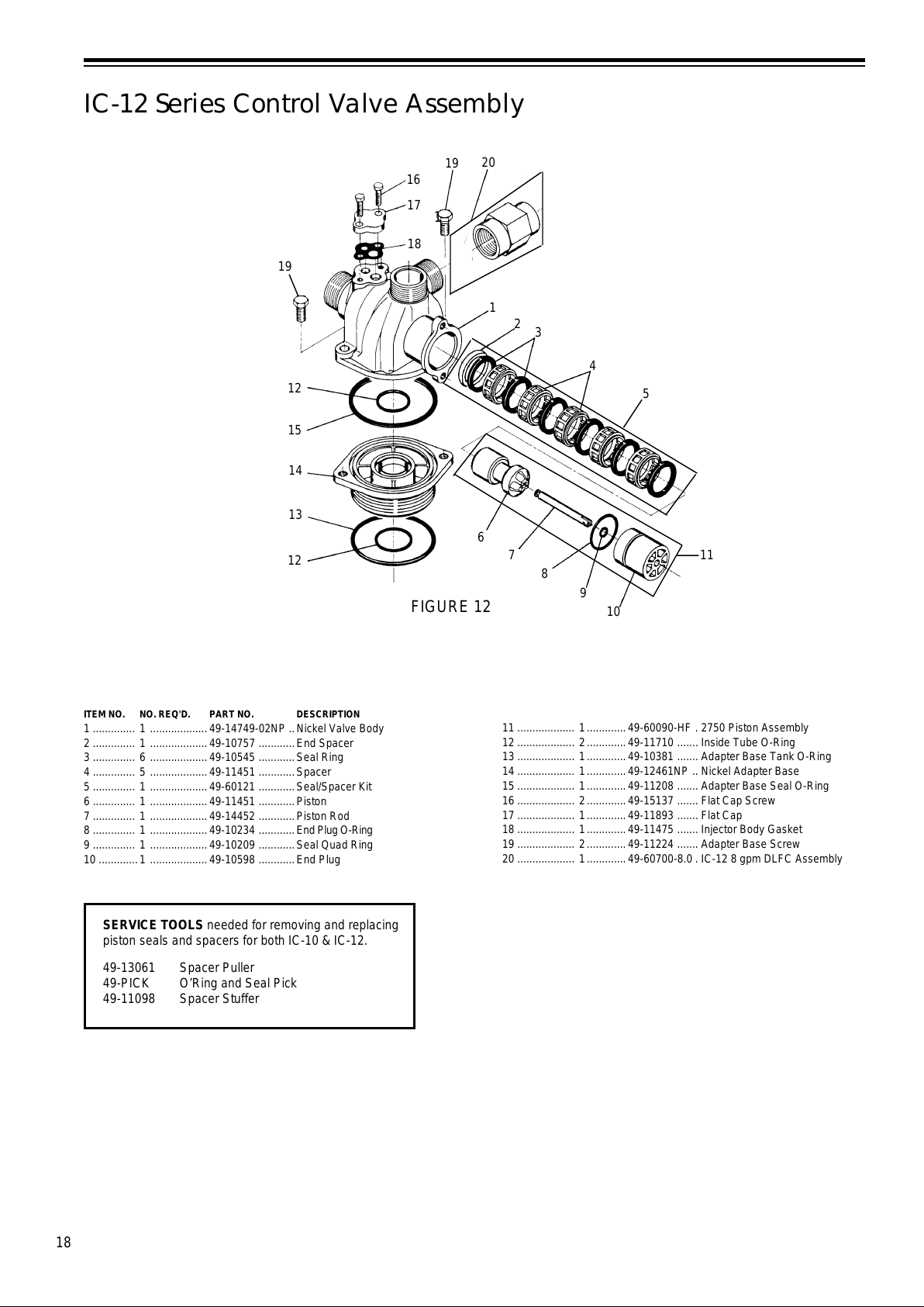
18
1
IC-12 Series Control Valve Assembly
14
1
2
3
4
5
11
10
9
8
7
6
12
13
15
12
19
20
16
17
18
ITEM NO. NO. REQ'D. PART NO. DESCRIPTION
1 .............. 1 ...................49-14749-02NP .. Nickel Valve Body
2 .............. 1 ...................49-10757 ............End Spacer
3 .............. 6 ...................49-10545 ............Seal Ring
4 .............. 5 ...................49-11451 ............Spacer
5 .............. 1 ...................49-60121 ............Seal/Spacer Kit
6 .............. 1 ...................49-11451 ............Piston
7 .............. 1 ...................49-14452 ............Piston Rod
8 .............. 1 ...................49-10234 ............End Plug O-Ring
9 .............. 1 ...................49-10209 ............Seal Quad Ring
10 .............1 ...................49-10598 ............End Plug
19
FIGURE 12
11 ................... 1.............49-60090-HF . 2750 Piston Assembly
12 ................... 2.............49-11710 ....... Inside Tube O-Ring
13 ................... 1.............49-10381 ....... Adapter Base Tank O-Ring
14 ................... 1.............49-12461NP .. Nickel Adapter Base
15 ................... 1.............49-11208 ....... Adapter Base Seal O-Ring
16 ................... 2.............49-15137 ....... Flat Cap Screw
17 ................... 1.............49-11893 ....... Flat Cap
18 ................... 1.............49-11475 ....... Injector Body Gasket
19 ................... 2.............49-11224 ....... Adapter Base Screw
20 ................... 1.............49-60700-8.0 . IC-12 8 gpm DLFC Assembly
SERVICE TOOLS needed for removing and replacing
piston seals and spacers for both IC-10 & IC-12.
49-13061 Spacer Puller
49-PICK O’Ring and Seal Pick
49-11098 Spacer Stuffer
All manuals and user guides at all-guides.com
Page 19
19
Instructions for Replacing
Piston Assembly and Seal Kit
Replacing Piston Assembly
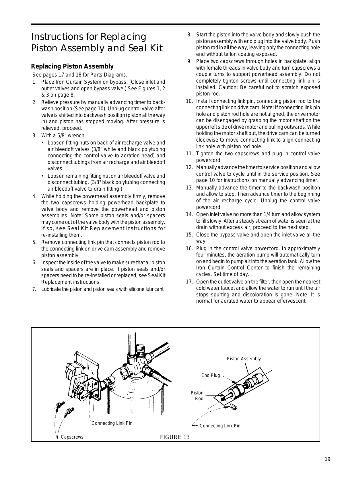
See pages 17 and 18 for Parts Diagrams.
1. Place Iron Curtain System on bypass. (Close inlet and
outlet valves and open bypass valve.) See Figures 1, 2
& 3 on page 8.
2. Relieve pressure by manually advancing timer to back-
wash position (See page 10). Unplug control valve after
valve is shifted into backwash position (piston all the way
in) and piston has stopped moving. After pressure is
relieved, proceed.
3. With a 5/8" wrench
• Loosen fitting nuts on back of air recharge valve and
air bleedoff valves (3/8" white and black polytubing
connecting the control valve to aeration head) and
disconnect tubings from air recharge and air bleedoff
valves.
• Loosen remaining fitting nut on air bleedoff valve and
disconnect tubing. (3/8" black polytubing connecting
air bleedoff valve to drain fitting.)
4. While holding the powerhead assembly firmly, remove
the two capscrews holding powerhead backplate to
valve body and remove the powerhead and piston
assemblies. Note: Some piston seals and/or spacers
may come out of the valve body with the piston assembly.
If so, see Seal Kit Replacement instructions fo
r
re-installing them.
5. Remove connecting link pin that connects piston rod to
the connecting link on drive cam assembly and remove
piston assembly.
6. Inspect the inside of the valve to make sure that all piston
seals and spacers are in place. If piston seals and/or
spacers need to be re-installed or replaced, see Seal Kit
Replacement instructions.
7. Lubricate the piston and piston seals with silicone lubricant.
8. Start the piston into the valve body and slowly push the
piston assembly with end plug into the valve body. Push
piston rod in all the way, leaving only the connecting hole
end without teflon coating exposed.
9. Place two capscrews through holes in backplate, align
with female threads in valve body and turn capscrews a
couple turns to support powerhead assembly. Do not
completely tighten screws until connecting link pin is
installed. Caution: Be careful not to scratch exposed
piston rod.
10. Install connecting link pin, connecting piston rod to the
connecting link on drive cam. Note: If connecting link pin
hole and piston rod hole are not aligned, the drive motor
can be disengaged by grasping the motor shaft on the
upper left side of drive motor and pulling outwards. While
holding the motor shaft out, the drive cam can be turned
clockwise to move connecting link to align connecting
link hole with piston rod hole.
11. Tighten the two capscrews and plug in control valve
powercord.
12. Manually advance the timer to service position and allow
control valve to cycle until in the service position. See
page 10 for instructions on manually advancing timer.
13. Manually advance the timer to the backwash position
and allow to stop. Then advance timer to the beginning
of the air recharge cycle. Unplug the control valve
powercord.
14. Open inlet valve no more than 1/4 turn and allow system
to fill slowly. After a steady stream of water is seen at the
drain without excess air, proceed to the next step.
15. Close the bypass valve and open the inlet valve all the
way.
16. Plug in the control valve powercord. In approximately
four minutes, the aeration pump will automatically turn
on and begin to pump air into the aeration tank. Allow the
Iron Curtain Control Center to finish the remaining
cycles. Set time of day.
17. Open the outlet valve on the filter, then open the nearest
cold water faucet and allow the water to run until the air
stops spurting and discoloration is gone. Note: It is
normal for aerated water to appear effervescent.
Piston
Rod
Piston Assembly
Capscrews
Connecting Link Pin
End Plug
Connecting Link Pin
FIGURE 13
All manuals and user guides at all-guides.com
Page 20
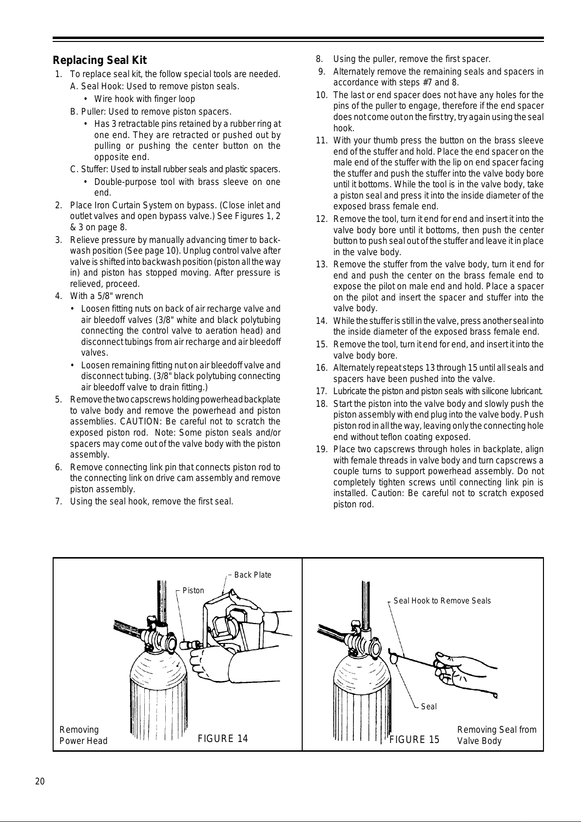
20
Removing
Power Head
Removing Seal from
Valve Body
Piston
Back Plate
Seal Hook to Remove Seals
Seal
FIGURE 14
FIGURE 15
8. Using the puller, remove the first spacer.
9. Alternately remove the remaining seals and spacers in
accordance with steps #7 and 8.
10. The last or end spacer does not have any holes for the
pins of the puller to engage, therefore if the end spacer
does not come out on the first try, try again using the seal
hook.
11. With your thumb press the button on the brass sleeve
end of the stuffer and hold. Place the end spacer on the
male end of the stuffer with the lip on end spacer facing
the stuffer and push the stuffer into the valve body bore
until it bottoms. While the tool is in the valve body, take
a piston seal and press it into the inside diameter of the
exposed brass female end.
12. Remove the tool, turn it end for end and insert it into the
valve body bore until it bottoms, then push the center
button to push seal out of the stuffer and leave it in place
in the valve body.
13. Remove the stuffer from the valve body, turn it end for
end and push the center on the brass female end to
expose the pilot on male end and hold. Place a spacer
on the pilot and insert the spacer and stuffer into the
valve body.
14. While the stuffer is still in the valve, press another seal into
the inside diameter of the exposed brass female end.
15. Remove the tool, turn it end for end, and insert it into the
valve body bore.
16. Alternately repeat steps 13 through 15 until all seals and
spacers have been pushed into the valve.
17. Lubricate the piston and piston seals with silicone lubricant.
18. Start the piston into the valve body and slowly push the
piston assembly with end plug into the valve body. Push
piston rod in all the way, leaving only the connecting hole
end without teflon coating exposed.
19. Place two capscrews through holes in backplate, align
with female threads in valve body and turn capscrews a
couple turns to support powerhead assembly. Do not
completely tighten screws until connecting link pin is
installed. Caution: Be careful not to scratch exposed
piston rod.
Replacing Seal Kit
1. To replace seal kit, the follow special tools are needed.
A. Seal Hook: Used to remove piston seals.
• Wire hook with finger loop
B. Puller: Used to remove piston spacers.
• Has 3 retractable pins retained by a rubber ring at
one end. They are retracted or pushed out by
pulling or pushing the center button on the
opposite end.
C. S tuffer: Used to install rubber seals and plastic spacers.
• Double-purpose tool with brass sleeve on one
end.
2. Place Iron Curtain System on bypass. (Close inlet and
outlet valves and open bypass valve.) See Figures 1, 2
& 3 on page 8.
3. Relieve pressure by manually advancing timer to back-
wash position (See page 10). Unplug control valve after
valve is shifted into backwash position (piston all the way
in) and piston has stopped moving. After pressure is
relieved, proceed.
4. With a 5/8" wrench
• Loosen fitting nuts on back of air recharge valve and
air bleedoff valves (3/8" white and black polytubing
connecting the control valve to aeration head) and
disconnect tubings from air recharge and air bleedoff
valves.
• Loosen remaining fitting nut on air bleedoff valve and
disconnect tubing. (3/8" black polytubing connecting
air bleedoff valve to drain fitting.)
5. Remove the two capscrews holding powerhead backplate
to valve body and remove the powerhead and piston
assemblies. CAUTION: Be careful not to scratch the
exposed piston rod. Note: Some piston seals and/or
spacers may come out of the valve body with the piston
assembly.
6. Remove connecting link pin that connects piston rod to
the connecting link on drive cam assembly and remove
piston assembly.
7. Using the seal hook, remove the first seal.
All manuals and user guides at all-guides.com
Page 21
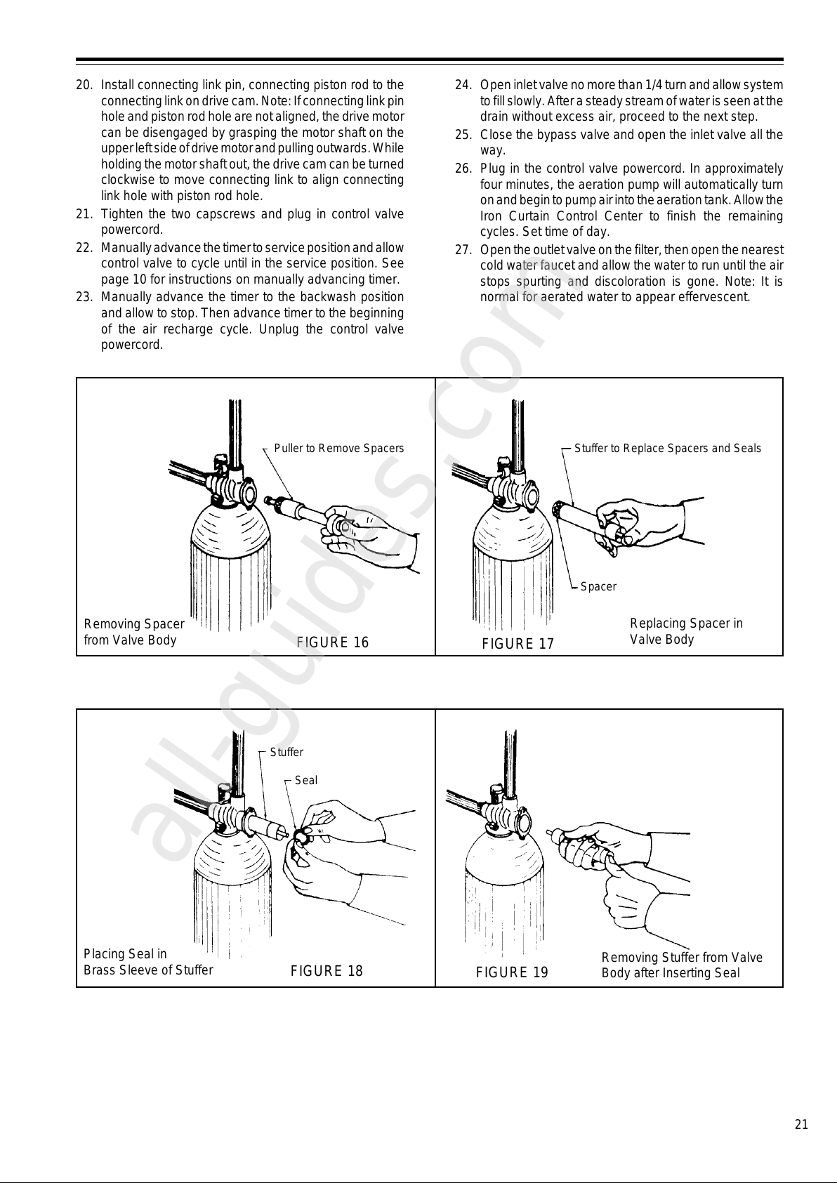
21
Removing Spacer
from Valve Body
Replacing Spacer in
Valve Body
Placing Seal in
Brass Sleeve of Stuffer
Removing Stuffer from Valve
Body after Inserting Seal
Puller to Remove Spacers
Stuffer to Replace Spacers and Seals
Spacer
Stuffer
Seal
FIGURE 18
FIGURE 19
FIGURE 16
FIGURE 17
24. Open inlet valve no more than 1/4 turn and allow system
to fill slowly. After a steady stream of water is seen at the
drain without excess air, proceed to the next step.
25. Close the bypass valve and open the inlet valve all the
way.
26. Plug in the control valve powercord. In approximately
four minutes, the aeration pump will automatically turn
on and begin to pump air into the aeration tank. Allow the
Iron Curtain Control Center to finish the remaining
cycles. Set time of day.
27. Open the outlet valve on the filter, then open the nearest
cold water faucet and allow the water to run until the air
stops spurting and discoloration is gone. Note: It is
normal for aerated water to appear effervescent.
20. Install connecting link pin, connecting piston rod to the
connecting link on drive cam. Note: If connecting link pin
hole and piston rod hole are not aligned, the drive motor
can be disengaged by grasping the motor shaft on the
upper left side of drive motor and pulling outwards. While
holding the motor shaft out, the drive cam can be turned
clockwise to move connecting link to align connecting
link hole with piston rod hole.
21. Tighten the two capscrews and plug in control valve
powercord.
22. Manually advance the timer to service position and allow
control valve to cycle until in the service position. See
page 10 for instructions on manually advancing timer.
23. Manually advance the timer to the backwash position
and allow to stop. Then advance timer to the beginning
of the air recharge cycle. Unplug the control valve
powercord.
All manuals and user guides at all-guides.com
all-guides.com
Page 22
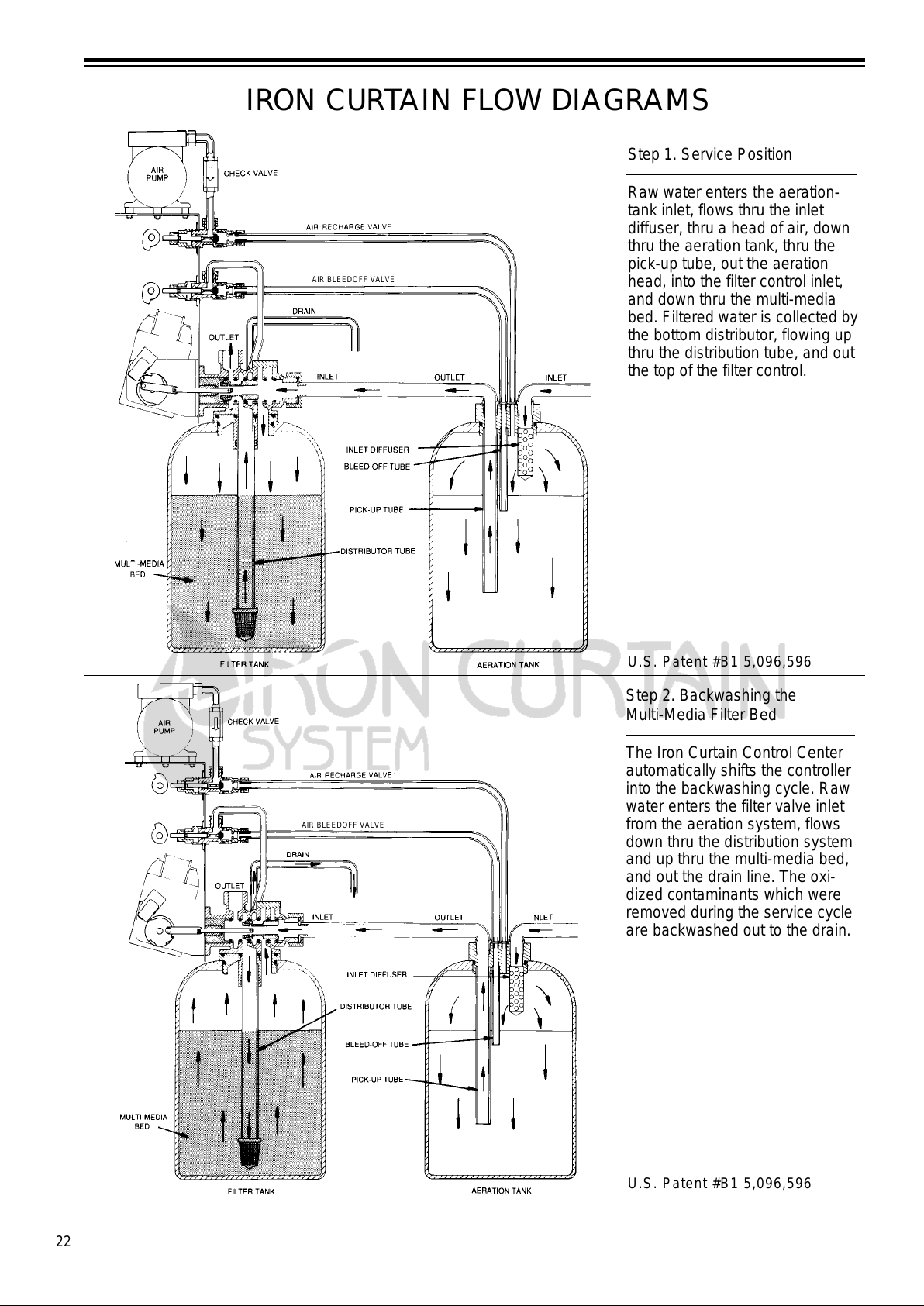
22
IRON CURTAIN FLOW DIAGRAMS
Step 1. Service Position
Raw water enters the aeration-
tank inlet, flows thru the inlet
diffuser, thru a head of air, down
thru the aeration tank, thru the
pick-up tube, out the aeration
head, into the filter control inlet,
and down thru the multi-media
bed. Filtered water is collected by
the bottom distributor, flowing up
thru the distribution tube, and out
the top of the filter control.
U.S. Patent #B1 5,096,596
U.S. Patent #B1 5,096,596
Step 2. Backwashing the
Multi-Media Filter Bed
The Iron Curtain Control Center
automatically shifts the controller
into the backwashing cycle. Raw
water enters the filter valve inlet
from the aeration system, flows
down thru the distribution system
and up thru the multi-media bed,
and out the drain line. The oxi-
dized contaminants which were
removed during the service cycle
are backwashed out to the drain.
AIR BLEEDOFF VALVE
AIR BLEEDOFF VALVE
All manuals and user guides at all-guides.com
Page 23
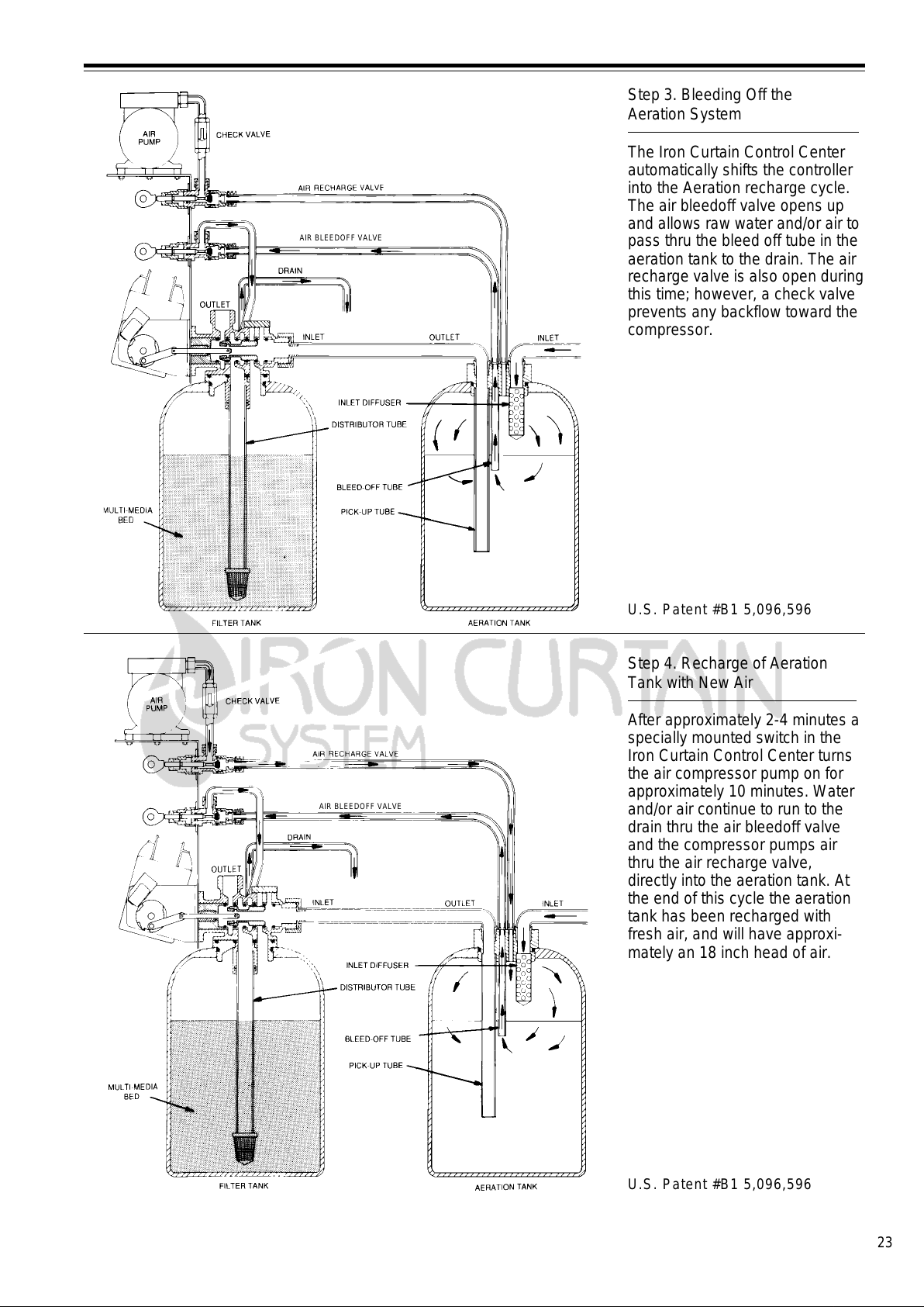
23
Step 3. Bleeding Off the
Aeration System
The Iron Curtain Control Center
automatically shifts the controller
into the Aeration recharge cycle.
The air bleedoff valve opens up
and allows raw water and/or air to
pass thru the bleed off tube in the
aeration tank to the drain. The air
recharge valve is also open during
this time; however, a check valve
prevents any backflow toward the
compressor.
U.S. Patent #B1 5,096,596
U.S. Patent #B1 5,096,596
Step 4. Recharge of Aeration
Tank with New Air
After approximately 2-4 minutes a
specially mounted switch in the
Iron Curtain Control Center turns
the air compressor pump on for
approximately 10 minutes. Water
and/or air continue to run to the
drain thru the air bleedoff valve
and the compressor pumps air
thru the air recharge valve,
directly into the aeration tank. At
the end of this cycle the aeration
tank has been recharged with
fresh air, and will have approxi-
mately an 18 inch head of air.
AIR BLEEDOFF VALVE
AIR BLEEDOFF VALVE
All manuals and user guides at all-guides.com
Page 24
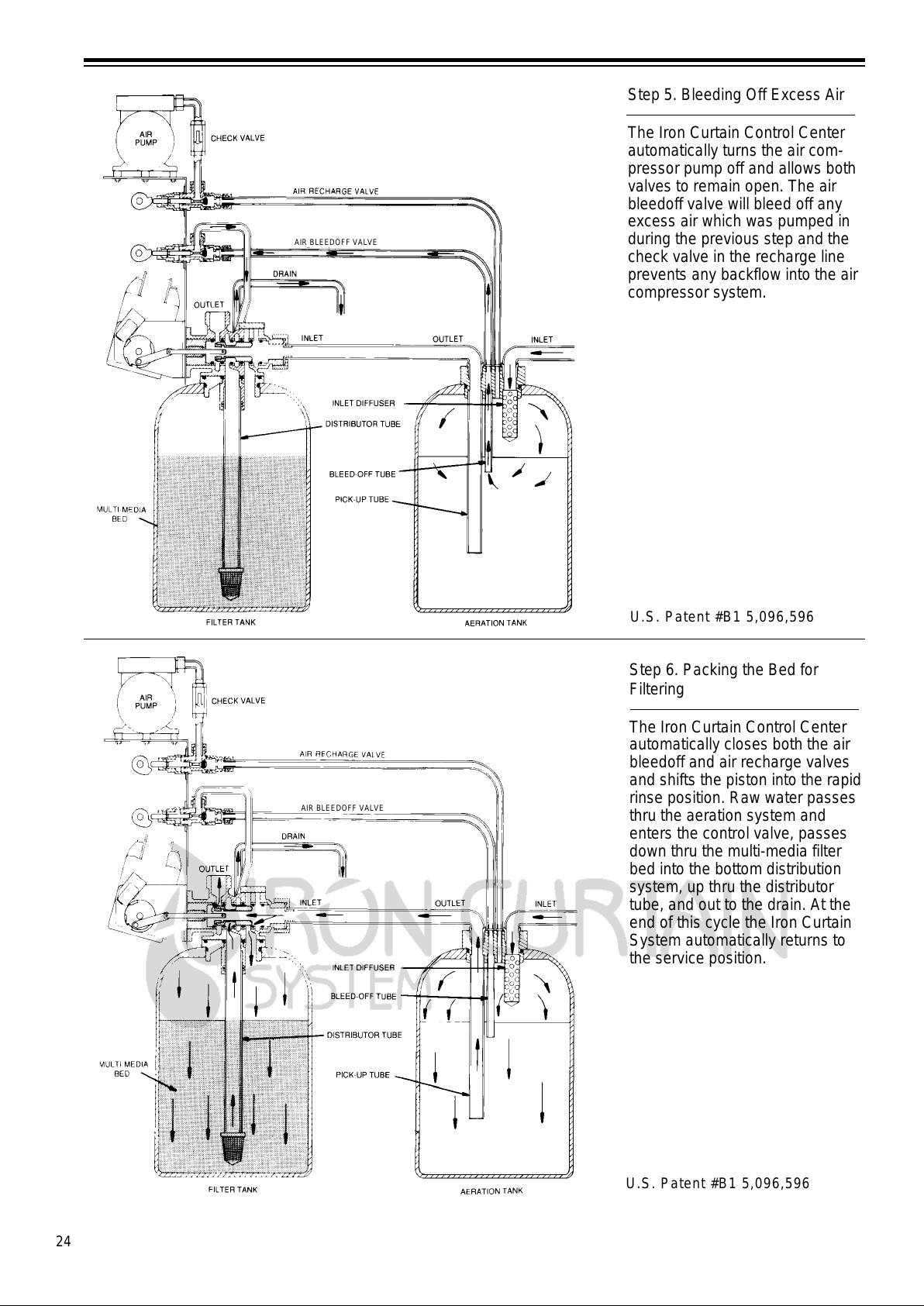
24
Step 5. Bleeding Off Excess Air
The Iron Curtain Control Center
automatically turns the air com-
pressor pump off and allows both
valves to remain open. The air
bleedoff valve will bleed off any
excess air which was pumped in
during the previous step and the
check valve in the recharge line
prevents any backflow into the air
compressor system.
U.S. Patent #B1 5,096,596
Step 6. Packing the Bed for
Filtering
The Iron Curtain Control Center
automatically closes both the air
bleedoff and air recharge valves
and shifts the piston into the rapid
rinse position. Raw water passes
thru the aeration system and
enters the control valve, passes
down thru the multi-media filter
bed into the bottom distribution
system, up thru the distributor
tube, and out to the drain. At the
end of this cycle the Iron Curtain
System automatically returns to
the service position.
U.S. Patent #B1 5,096,596
AIR BLEEDOFF VALVE
AIR BLEEDOFF VALVE
All manuals and user guides at all-guides.com
Page 25
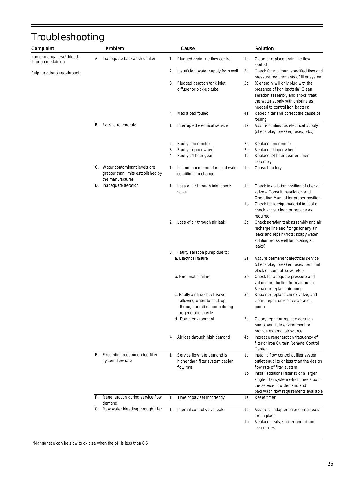
25
1a. Clean or replace drain line flow
control
2a. Check for minimum specified flow and
pressure requirements of filter system
3a. (Generally will only plug with the
presence of iron bacteria) Clean
aeration assembly and shock treat
the water supply with chlorine as
needed to control iron bacteria
4a. Rebed filter and correct the cause of
fouling
1a. Assure continuous electrical supply
(check plug, breaker, fuses, etc.)
2a. Replace timer motor
3a. Replace skipper wheel
4a. Replace 24 hour gear or timer
assembly
1a. Consult factory
1a. Check installation position of check
valve – Consult Installation and
Operation Manual for proper position
1b. Check for foreign material in seat of
check valve, clean or replace as
required
2a. Check aeration tank assembly and air
recharge line and fittings for any air
leaks and repair (Note: soapy water
solution works well for locating air
leaks)
3a. Assure permanent electrical service
(check plug, breaker, fuses, terminal
block on control valve, etc.)
3b. Check for adequate pressure and
volume production from air pump.
Repair or replace air pump
3c. Repair or replace check valve, and
clean, repair or replace aeration
pump
3d. Clean, repair or replace aeration
pump, ventilate environment or
provide external air source
4a. Increase regeneration frequency of
filter or Iron Curtain Remote Control
Center
1a. Install a flow control at filter system
outlet equal to or less than the design
flow rate of filter system
1b. Install additional filter(s) or a larger
single filter system which meets both
the service flow demand and
backwash flow requirements available
1a. Reset timer
1a. Assure all adapter base o-ring seals
are in place
1b. Replace seals, spacer and piston
assemblies
Troubleshooting
Complaint Problem Cause Solution
Iron or manganese* bleed-
through or staining
Sulphur odor bleed-through
*Manganese can be slow to oxidize when the pH is less than 8.5
1. Plugged drain line flow control
2. Insufficient water supply from well
3. Plugged aeration tank inlet
diffuser or pick-up tube
4. Media bed fouled
1. Interrupted electrical service
2. Faulty timer motor
3. Faulty skipper wheel
4. Faulty 24 hour gear
1. It is not uncommon for local water
conditions to change
1. Loss of air through inlet check
valve
2. Loss of air through air leak
3. Faulty aeration pump due to:
a. Electrical failure
b. Pneumatic failure
c. Faulty air line check valve
allowing water to back up
through aeration pump during
regeneration cycle
d. Damp environment
4. Air loss through high demand
1. Service flow rate demand is
higher than filter system design
flow rate
1. Time of day set incorrectly
1. Internal control valve leak
A. Inadequate backwash of filter
B. Fails to regenerate
C. Water contaminant levels are
greater than limits established by
the manufacturer
D. Inadequate aeration
E. Exceeding recommended filter
system flow rate
F. Regeneration during service flow
demand
G. Raw water bleeding through filter
All manuals and user guides at all-guides.com
Page 26
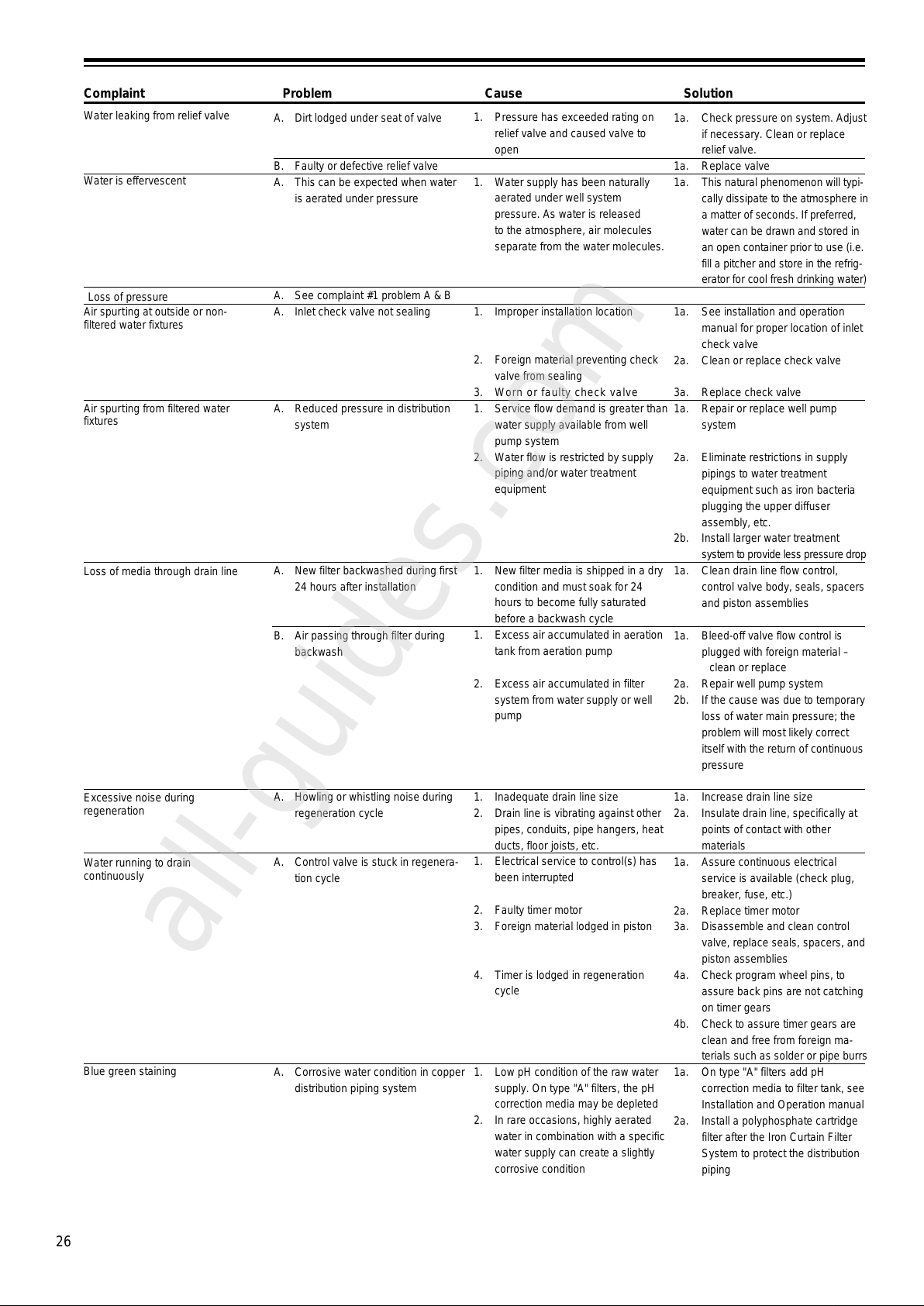
26
Complaint Problem Cause Solution
A. Dirt lodged under seat of valve
B. Faulty or defective relief valve
A. This can be expected when water
is aerated under pressure
A. See complaint #1 problem A & B
A. Inlet check valve not sealing
A. Reduced pressure in distribution
system
A. New filter backwashed during first
24 hours after installation
B. Air passing through filter during
backwash
A. Howling or whistling noise during
regeneration cycle
A. Control valve is stuck in regenera-
tion cycle
A. Corrosive water condition in copper
distribution piping system
Air spurting from filtered water
fixtures
Water leaking from relief valve
Water is effervescent
1. Pressure has exceeded rating on
relief valve and caused valve to
open
1. Water supply has been naturally
aerated under well system
pressure. As water is released
to the atmosphere, air molecules
separate from the water molecules.
1. Improper installation location
2. Foreign material preventing check
valve from sealing
3. Worn or faulty check valve
1. Service flow demand is greater than
water supply available from well
pump system
2. Water flow is restricted by supply
piping and/or water treatment
equipment
1. New filter media is shipped in a dry
condition and must soak for 24
hours to become fully saturated
before a backwash cycle
1. Excess air accumulated in aeration
tank from aeration pump
2. Excess air accumulated in filter
system from water supply or well
pump
1. Inadequate drain line size
2. Drain line is vibrating against other
pipes, conduits, pipe hangers, heat
ducts, floor joists, etc.
1. Electrical service to control(s) has
been interrupted
2. Faulty timer motor
3. Foreign material lodged in piston
4. Timer is lodged in regeneration
cycle
1. Low pH condition of the raw water
supply. On type "A" filters, the pH
correction media may be depleted
2. In rare occasions, highly aerated
water in combination with a specific
water supply can create a slightly
corrosive condition
Loss of pressure
Air spurting at outside or non-
filtered water fixtures
Loss of media through drain line
Excessive noise during
regeneration
Water running to drain
continuously
1a. Check pressure on system. Adjust
if necessary. Clean or replace
relief valve.
1a. Replace valve
1a. This natural phenomenon will typi-
cally dissipate to the atmosphere in
a matter of seconds. If preferred,
water can be drawn and stored in
an open container prior to use (i.e.
fill a pitcher and store in the refrig-
erator for cool fresh drinking water)
1a. See installation and operation
manual for proper location of inlet
check valve
2a. Clean or replace check valve
3a. Replace check valve
1a. Repair or replace well pump
system
2a. Eliminate restrictions in supply
pipings to water treatment
equipment such as iron bacteria
plugging the upper diffuser
assembly, etc.
2b. Install larger water treatment
system to provide less pressure drop
1a. Clean drain line flow control,
control valve body, seals, spacers
and piston assemblies
1a. Bleed-off valve flow control is
plugged with foreign material –
clean or replace
2a. Repair well pump system
2b. If the cause was due to temporary
loss of water main pressure; the
problem will most likely correct
itself with the return of continuous
pressure
1a. Increase drain line size
2a. Insulate drain line, specifically at
points of contact with other
materials
1a. Assure continuous electrical
service is available (check plug,
breaker, fuse, etc.)
2a. Replace timer motor
3a. Disassemble and clean control
valve, replace seals, spacers, and
piston assemblies
4a. Check program wheel pins, to
assure back pins are not catching
on timer gears
4b. Check to assure timer gears are
clean and free from foreign ma-
terials such as solder or pipe burrs
1a. On type "A" filters add pH
correction media to filter tank, see
Installation and Operation manual
2a. Install a polyphosphate cartridge
filter after the Iron Curtain Filter
System to protect the distribution
piping
Blue green staining
All manuals and user guides at all-guides.com
all-guides.com
Page 27
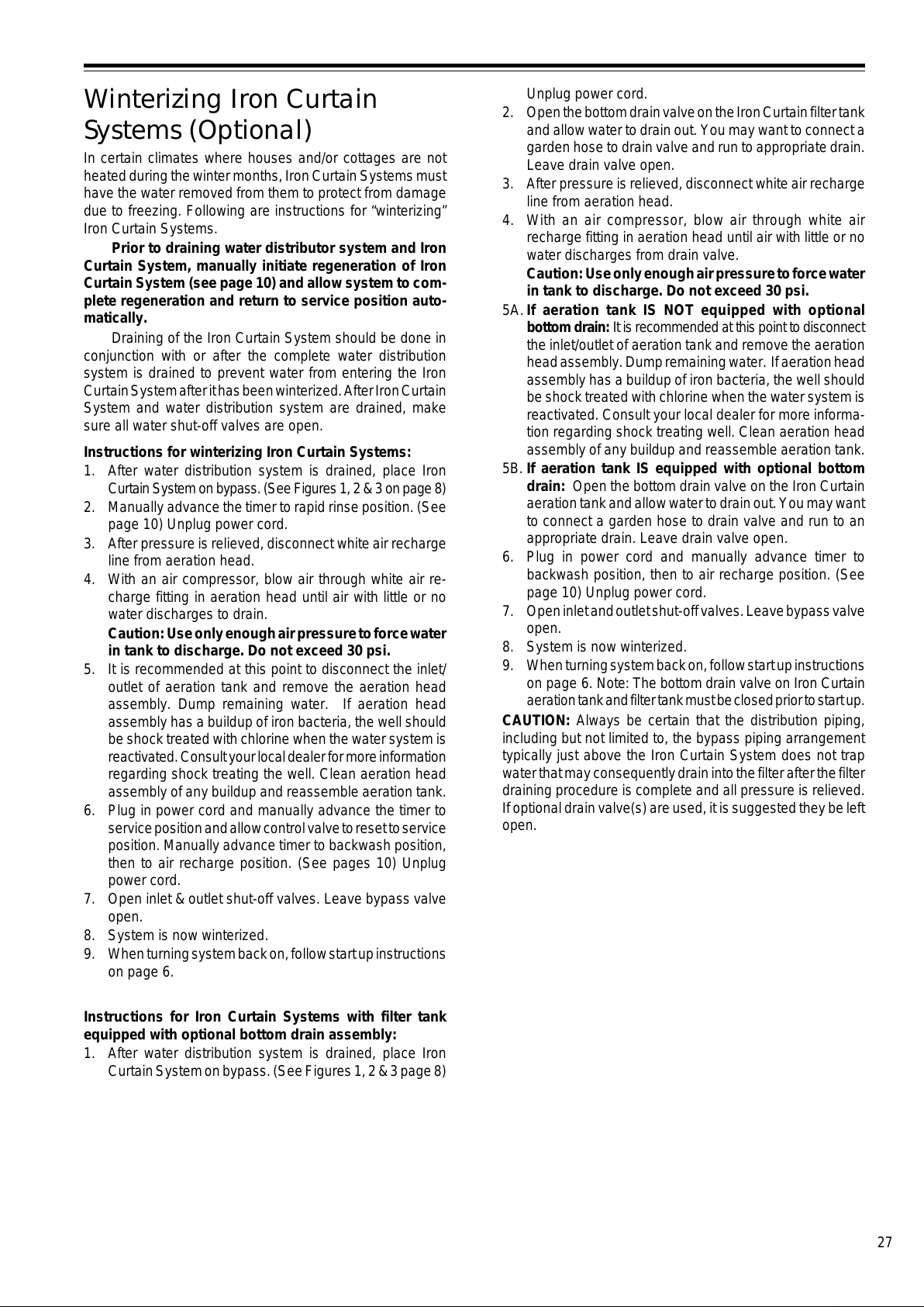
27
Winterizing Iron Curtain
Systems (Optional)
In certain climates where houses and/or cottages are not
heated during the winter months, Iron Curtain Systems must
have the water removed from them to protect from damage
due to freezing. Following are instructions for “winterizing”
Iron Curtain Systems.
Prior to draining water distributor system and Iron
Curtain System, manually initiate regeneration of Iron
Curtain System (see page 10) and allow system to com-
plete regeneration and return to service position auto-
matically.
Draining of the Iron Curtain System should be done in
conjunction with or after the complete water distribution
system is drained to prevent water from entering the Iron
Curtain System after it has been winterized. After Iron Curtain
System and water distribution system are drained, make
sure all water shut-off valves are open.
Instructions for winterizing Iron Curtain Systems:
1. After water distribution system is drained, place Iron
Curtain System on bypass. (See Figures 1, 2 & 3 on page 8)
2. Manually advance the timer to rapid rinse position. (See
page 10) Unplug power cord.
3. After pressure is relieved, disconnect white air recharge
line from aeration head.
4. With an air compressor, blow air through white air re-
charge fitting in aeration head until air with little or no
water discharges to drain.
Caution: Use only enough air pressure to force water
in tank to discharge. Do not exceed 30 psi.
5. It is recommended at this point to disconnect the inlet/
outlet of aeration tank and remove the aeration head
assembly. Dump remaining water. If aeration head
assembly has a buildup of iron bacteria, the well should
be shock treated with chlorine when the water system is
reactivated. Consult your local dealer for more information
regarding shock treating the well. Clean aeration head
assembly of any buildup and reassemble aeration tank.
6. Plug in power cord and manually advance the timer to
service position and allow control valve to reset to service
position. Manually advance timer to backwash position,
then to air recharge position. (See pages 10) Unplug
power cord.
7. Open inlet & outlet shut-off valves. Leave bypass valve
open.
8. System is now winterized.
9. When turning system back on, follow start up instructions
on page 6.
Instructions for Iron Curtain Systems with filter tank
equipped with optional bottom drain assembly:
1. After water distribution system is drained, place Iron
Curtain System on bypass. (See Figures 1, 2 & 3 page 8)
Unplug power cord.
2. Open the bottom drain valve on the Iron Curtain filter tank
and allow water to drain out. You may want to connect a
garden hose to drain valve and run to appropriate drain.
Leave drain valve open.
3. After pressure is relieved, disconnect white air recharge
line from aeration head.
4. With an air compressor, blow air through white air
recharge fitting in aeration head until air with little or no
water discharges from drain valve.
Caution: Use only enough air pressure to force water
in tank to discharge. Do not exceed 30 psi.
5A.If aeration tank IS NOT equipped with optional
bottom drain: It is recommended at this point to disconnect
the inlet/outlet of aeration tank and remove the aeration
head assembly. Dump remaining water. If aeration head
assembly has a buildup of iron bacteria, the well should
be shock treated with chlorine when the water system is
reactivated. Consult your local dealer for more informa-
tion regarding shock treating well. Clean aeration head
assembly of any buildup and reassemble aeration tank.
5B. If aeration tank IS equipped with optional bottom
drain: Open the bottom drain valve on the Iron Curtain
aeration tank and allow water to drain out. You may want
to connect a garden hose to drain valve and run to an
appropriate drain. Leave drain valve open.
6. Plug in power cord and manually advance timer to
backwash position, then to air recharge position. (See
page 10) Unplug power cord.
7. Open inlet and outlet shut-off valves. Leave bypass valve
open.
8. System is now winterized.
9. When turning system back on, follow start up instructions
on page 6. Note: The bottom drain valve on Iron Curtain
aeration tank and filter tank must be closed prior to start up.
CAUTION: Always be certain that the distribution piping,
including but not limited to, the bypass piping arrangement
typically just above the Iron Curtain System does not trap
water that may consequently drain into the filter after the filter
draining procedure is complete and all pressure is relieved.
If optional drain valve(s) are used, it is suggested they be left
open.
All manuals and user guides at all-guides.com
Page 28
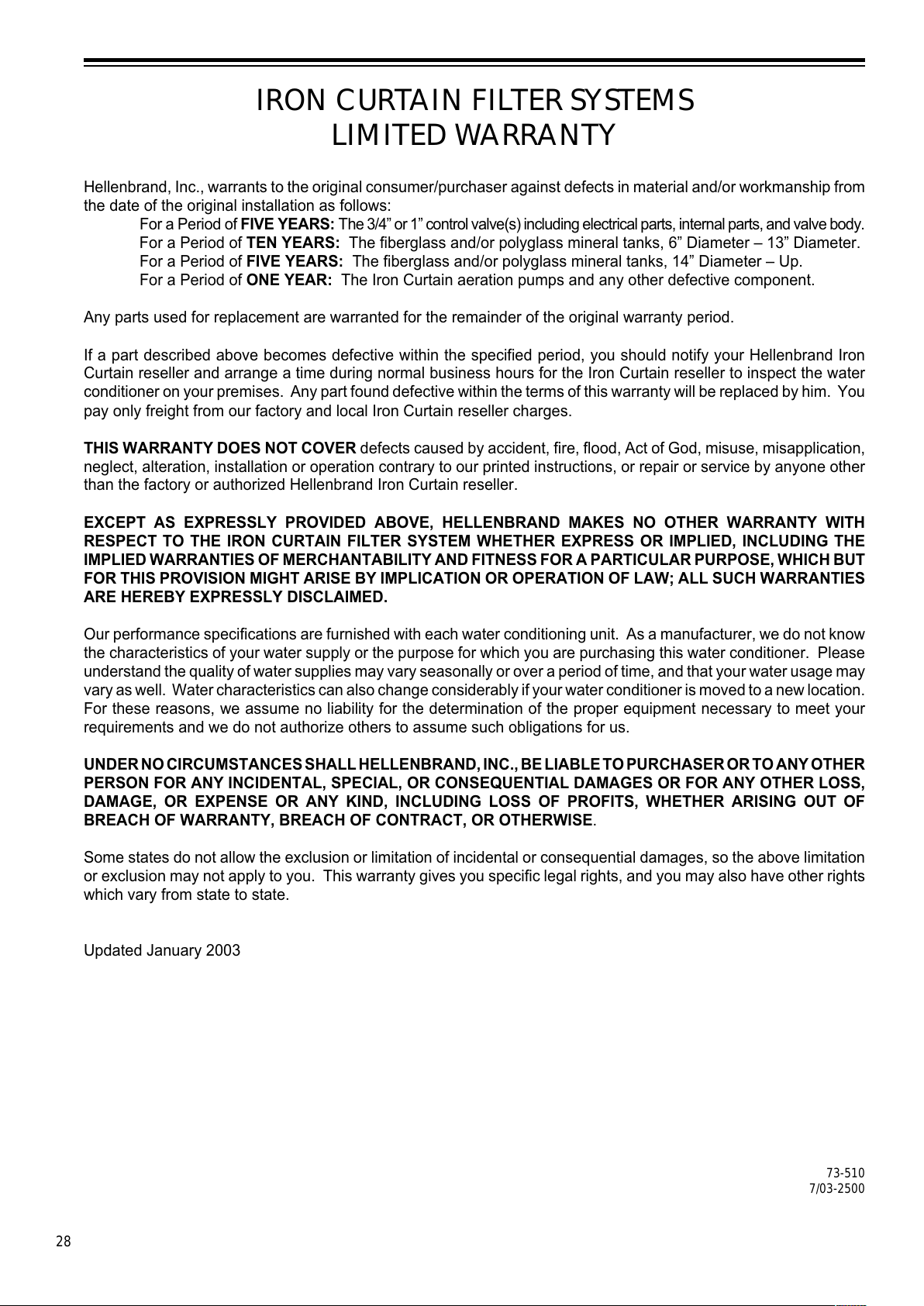
28
73-510
7/03-2500
IRON CURTAIN FILTER SYSTEMS
LIMITED WARRANTY
Hellenbrand, Inc., warrants to the original consumer/purchaser against defects in material and/or workmanship from
the date of the original installation as follows:
For a Period of FIVE YEARS: The 3/4” or 1” control valve(s) including electrical parts, internal parts, and valve body.
For a Period of TEN YEARS: The fiberglass and/or polyglass mineral tanks, 6” Diameter – 13” Diameter.
For a Period of FIVE YEARS: The fiberglass and/or polyglass mineral tanks, 14” Diameter – Up.
For a Period of ONE YEAR: The Iron Curtain aeration pumps and any other defective component.
Any parts used for replacement are warranted for the remainder of the original warranty period.
If a part described above becomes defective within the specified period, you should notify your Hellenbrand Iron
Curtain reseller and arrange a time during normal business hours for the Iron Curtain reseller to inspect the water
conditioner on your premises. Any part found defective within the terms of this warranty will be replaced by him. You
pay only freight from our factory and local Iron Curtain reseller charges.
THIS WARRANTY DOES NOT COVER defects caused by accident, fire, flood, Act of God, misuse, misapplication,
neglect, alteration, installation or operation contrary to our printed instructions, or repair or service by anyone other
than the factory or authorized Hellenbrand Iron Curtain reseller.
EXCEPT AS EXPRESSLY PROVIDED ABOVE, HELLENBRAND MAKES NO OTHER WARRANTY WITH
RESPECT TO THE IRON CURTAIN FILTER SYSTEM WHETHER EXPRESS OR IMPLIED, INCLUDING THE
IMPLIED WARRANTIES OF MERCHANTABILITY AND FITNESS FOR A PARTICULAR PURPOSE, WHICH BUT
FOR THIS PROVISION MIGHT ARISE BY IMPLICATION OR OPERATION OF LAW; ALL SUCH WARRANTIES
ARE HEREBY EXPRESSLY DISCLAIMED.
Our performance specifications are furnished with each water conditioning unit. As a manufacturer, we do not know
the characteristics of your water supply or the purpose for which you are purchasing this water conditioner. Please
understand the quality of water supplies may vary seasonally or over a period of time, and that your water usage may
vary as well. Water characteristics can also change considerably if your water conditioner is moved to a new location.
For these reasons, we assume no liability for the determination of the proper equipment necessary to meet your
requirements and we do not authorize others to assume such obligations for us.
UNDER NO CIRCUMSTANCES SHALL HELLENBRAND, INC., BE LIABLE TO PURCHASER OR TO ANY OTHER
PERSON FOR ANY INCIDENTAL, SPECIAL, OR CONSEQUENTIAL DAMAGES OR FOR ANY OTHER LOSS,
DAMAGE, OR EXPENSE OR ANY KIND, INCLUDING LOSS OF PROFITS, WHETHER ARISING OUT OF
BREACH OF WARRANTY, BREACH OF CONTRACT, OR OTHERWISE.
Some states do not allow the exclusion or limitation of incidental or consequential damages, so the above limitation
or exclusion may not apply to you. This warranty gives you specific legal rights, and you may also have other rights
which vary from state to state.
Updated January 2003
All manuals and user guides at all-guides.com
 Loading...