

Page 1
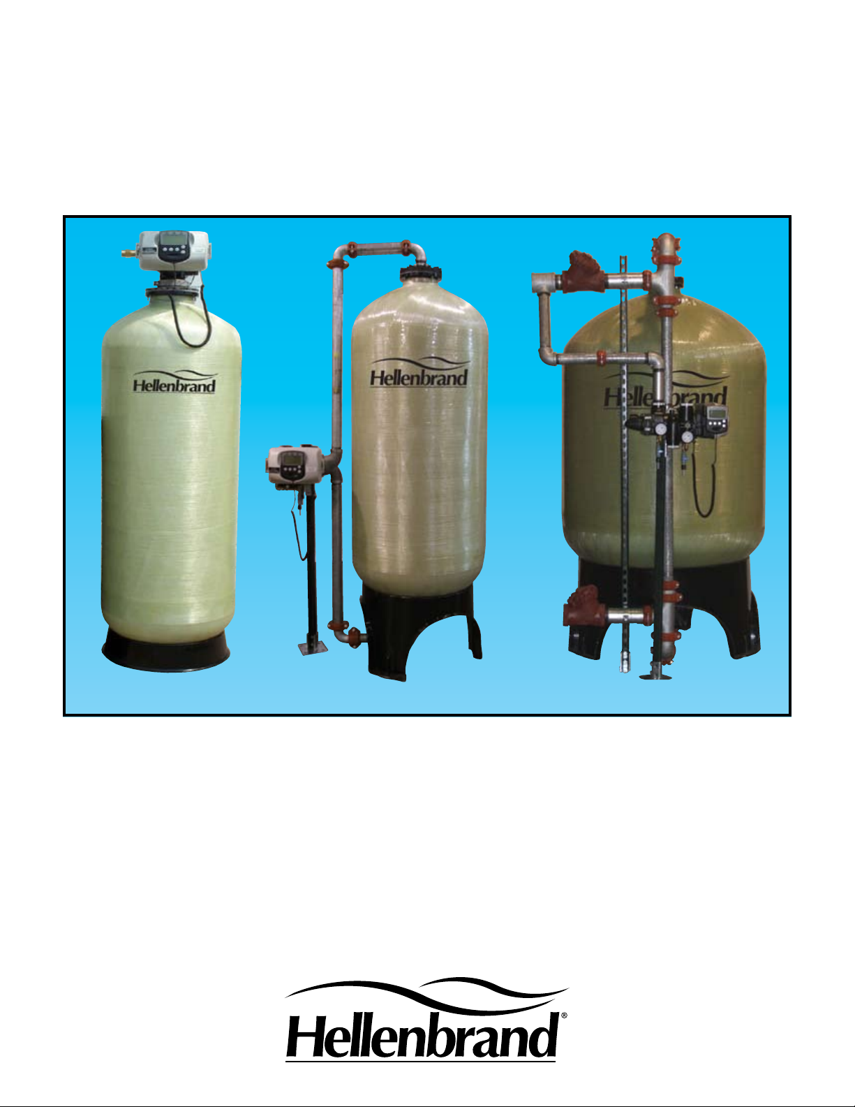
H200 & H200HF SERIES
WATER CONDITIONERS
H200 Top Mount
H200 Side Mount
H200HF Side Mount
For Commercial & Industrial Applications
Apartment Buildings
Boiler Water Treatment
Car Washes
Commercial Buildings
Condominiums
Factories
Hospitals
Laundries
Mobile Home Parks
Motels and Hotels
Nursing and Rest Homes
Ofce Buildings
Restaurants
Schools
Page 2
Hellenbrand Means Quality and Reliability
Since 1967, Hellenbrand, Inc. has provided water solutions to the water treatment industry in the
U.S. and around the world. Our growth in the water treatment industry is a direct result of providing high quality products and supporting the applications for those products with over 200+
years of industry knowledge before, during and after the sale, which has resulted in multiple applications over the years with the same customers.
H200 & H200HF Series Conditioners may either be top-mounted using a ange design or sidemounted using a side-mounted adapter, with either berglass or steel tanks. The H200 inlet/outlet opening is a two-inch FPT or 2.5” Victaulic. The H200HF "High Flow" Series uses a
side-mount design with 2.5”, 3” or 4” high ow service valves to provide higher ow rates with
minimal pressure loss. The lead free brass valve body has an NSF Approved Food Grade Electro-Deposited Epoxy Coating to protect against corrosion, both internally and externally. Utilizing
the proven technology of a piston and seal/spacer stack assembly and the powerful H200 micro-
processor you can operate up to four tanks in parallel, alternating or demand recall/stage by ow
and choose up to nine regeneration cycles in any order with a wide range of values for backwash,
brine draw, slow rinse, fast rinse, rell and service allowing you to customize the H200/H200HF
system for your particular application.
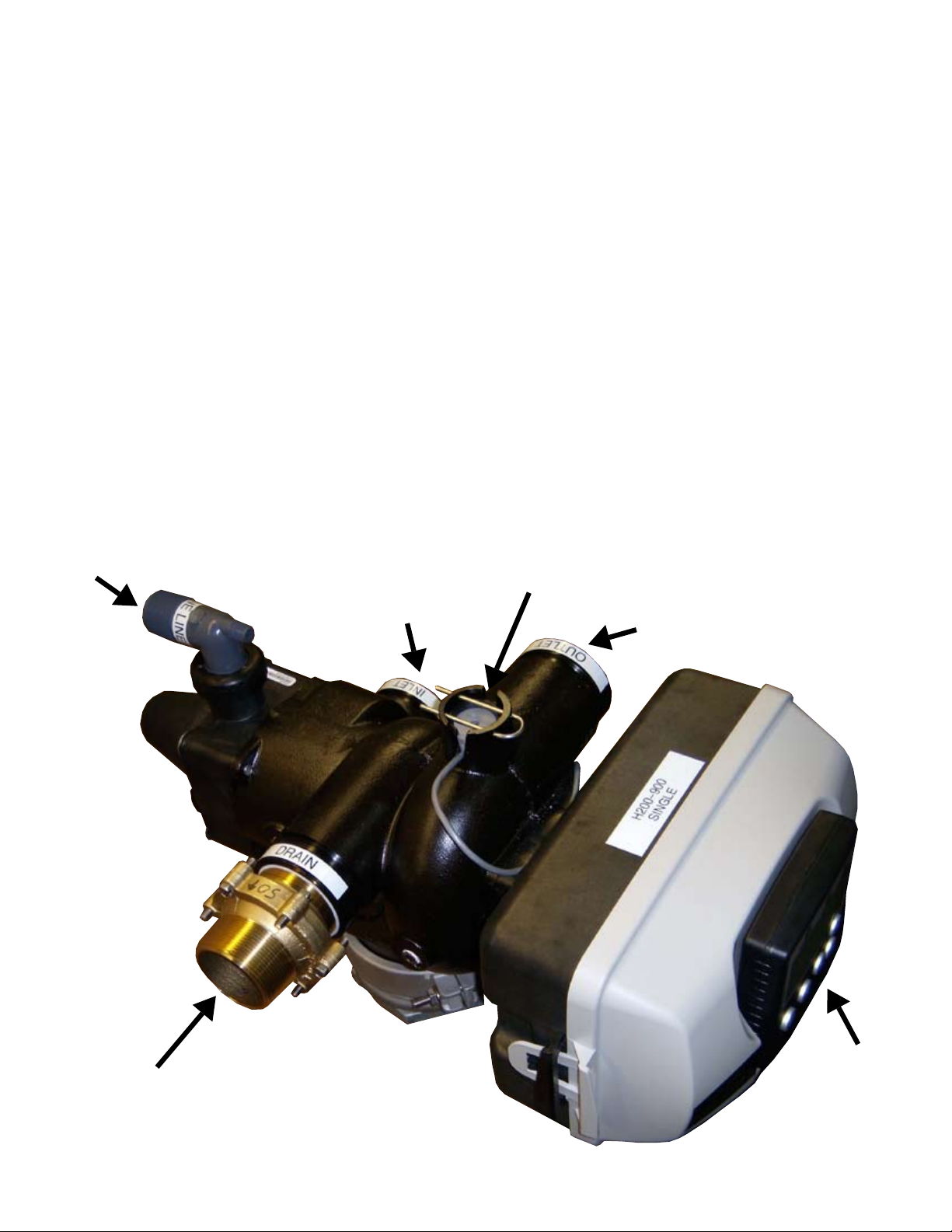
Brine Connector
Internal Meter (H200 Series Only)
Drain Connection
Inlet
Outlet
Removable
POD Display
2
Page 3
The H200 / H200HF is powerful, easy to use and packed with benets
• Solid state microprocessor can control from
one to four units allowing you system add on
capabilities as your needs grow.
• Regeneration may be initiated with a time
clock, meter delayed or meter immediate.
Up to nine fully programmable cycle times, that
•
can be moved around and repeated in various
orders for your particular application needs.
• Soft water brine rell reduces build up in brine
tank from hardness and iron present in the raw
water supply.
• Easy to use user screen shows Time of Day,
Current Flow Rate, Total Gallons Processed
and Volume/Days until Regeneration.
• Solid state microprocessor has a removable
POD display allowing you to remote mount the
POD on top-mounted systems for easy access.
• Economical built-in electronic meter on H200
Series requires no extra piping.
• Economical remote mount electronic meters
are available in a wide variety of sizes for the
H200HF Series.
• Both two-inch FPT and 2.5” Victaulic Inlet/
Outlet are standard on the H200 Series.
•
Lead free brass body with NSF Approved Food
Grade Electro-Deposited Epoxy Coating to protect internally and externally against corrosion.
• Corrosion free Noryl® backplate.
• Nema 3 Enclosure
• Optional Calendar Day Override from 1-28 days.
• 24-Volt output AC adapter is safe, comes with
a 15-foot cord for easy installation.
• Reliable and proven DC drive from our family
of H-Series Systems.
• Capacitor back-up with up to 24-hour power
carry over.
• Optional System Control Board enables the
addition of a third and fourth unit to be implemented into the system design. In addition
the system board can be utilized to operate
external devices like chemical feed pumps,
booster pumps, and to lock out an R.O. system. The available two sets of normally open
& normally closed auxiliary outputs can be
activated after the start of a regeneration, after
the start of a specied regeneration cycle, on
a set number of gallons during service, on a
set number of gallons during service, on a set
number of gallons during service & regeneration mode, while in standyby & regeneration
mode with a multi-tank system, or if a unit
would be in an Error Mode.
• Motorized Alternating Valve "MAV" Provides:
• Twin Alternating for H200 Top or Side
Mount Systems.
• Provides for no Raw Water By-Pass
during regeneration for H200 Top or
Side Mount Systems.
• Provides choices of treated or non-
treated water for regeneration.
• Separate source regeneration.
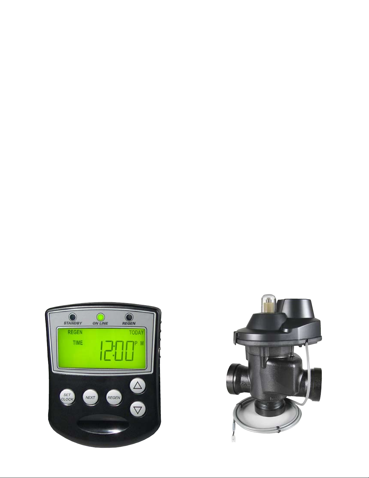
Removable POD Display
2" Motorized Alternating Valve "MAV"
Requires System Board For Operation
3
Page 4
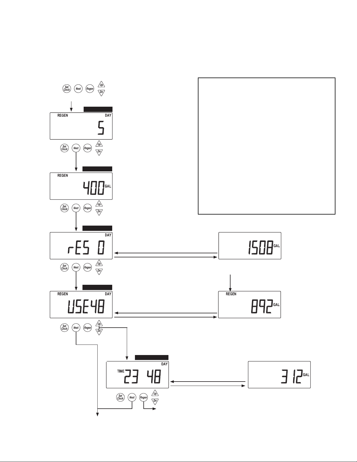
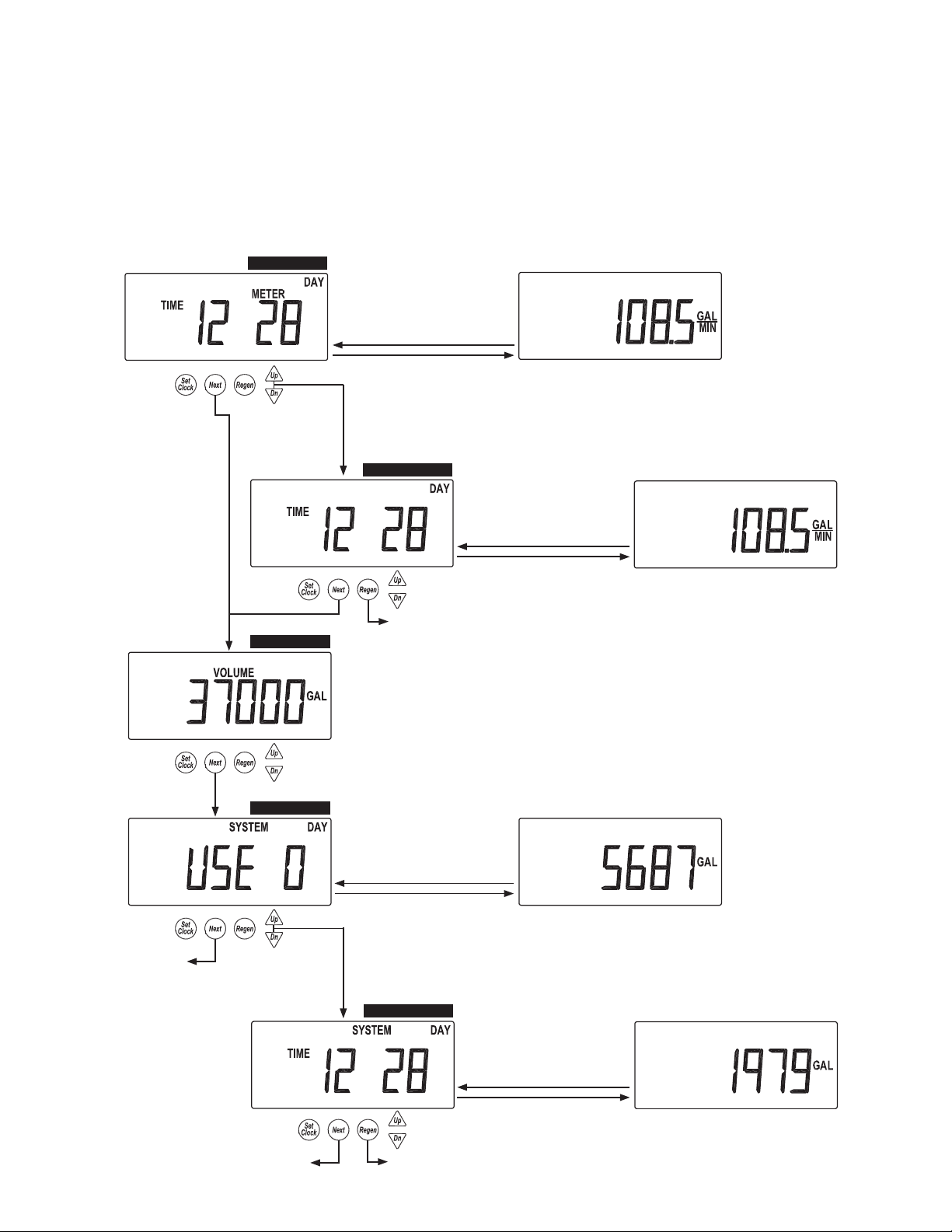
H200/H200HF Diagnostic and History Screens provide the
DIAGNOSTIC 1
Automatically Toggles
Automatically Toggles
Diagnostic 4
DIAGNOSTIC 2
DIAGNOSTIC 3
DIAGNOSTIC 4
DIAGNOSTIC 4-B
Page 20 WS2H Control Valve Manual
Diagnostic Screens
All Diagnostic History screens are resettable
with the History Reset sequence while in the
Diagnostics1 screen. Holding the Set Clock
and Regen buttons for > 3 seconds initiates a
totalizer or history reset.
Accessed by pressing UP and DOWN
simultaneously for >3 seconds.
DIAGNOSTICS 1
Days since the last regeneration.
DIAGNOSTICS 2
Gallons or Liters x1000 since the last
regeneration.
DIAGNOSTICS 3
Reserve history. This screen only appears if valve
is set to calculate Reserve in System Setup 7.
Use arrows to select a day.
0 = Today
1 = Yesterday
6 = 6 days ago (max.)
Reserve Value
DIAGNOSTICS 4
History of volume used.
Use arrows to select a day.
0 = Today
1 = Yesterday
63 = 63 days ago (max.)
REGEN will display if a
regeneration occurred that day.
Gallons Used
Simultaneously press
UP and DOWN.
DIAGNOSTICS 4-B
Hourly history of volume use. Use
the UP and DOWN arrow to select
the hours of the day from screen 4.
Volume used within the selected hour
Automatically Toggles
Returns to normal operation after 5 minutes.
water treatment operator with a wealth of information.
Diagnostic Screens
• Days since last regeneration
• Total volume treated since last regeneration
• Reserve history for the current day and
previous six-days
• Usage history by the hour for each of the
last 63 days
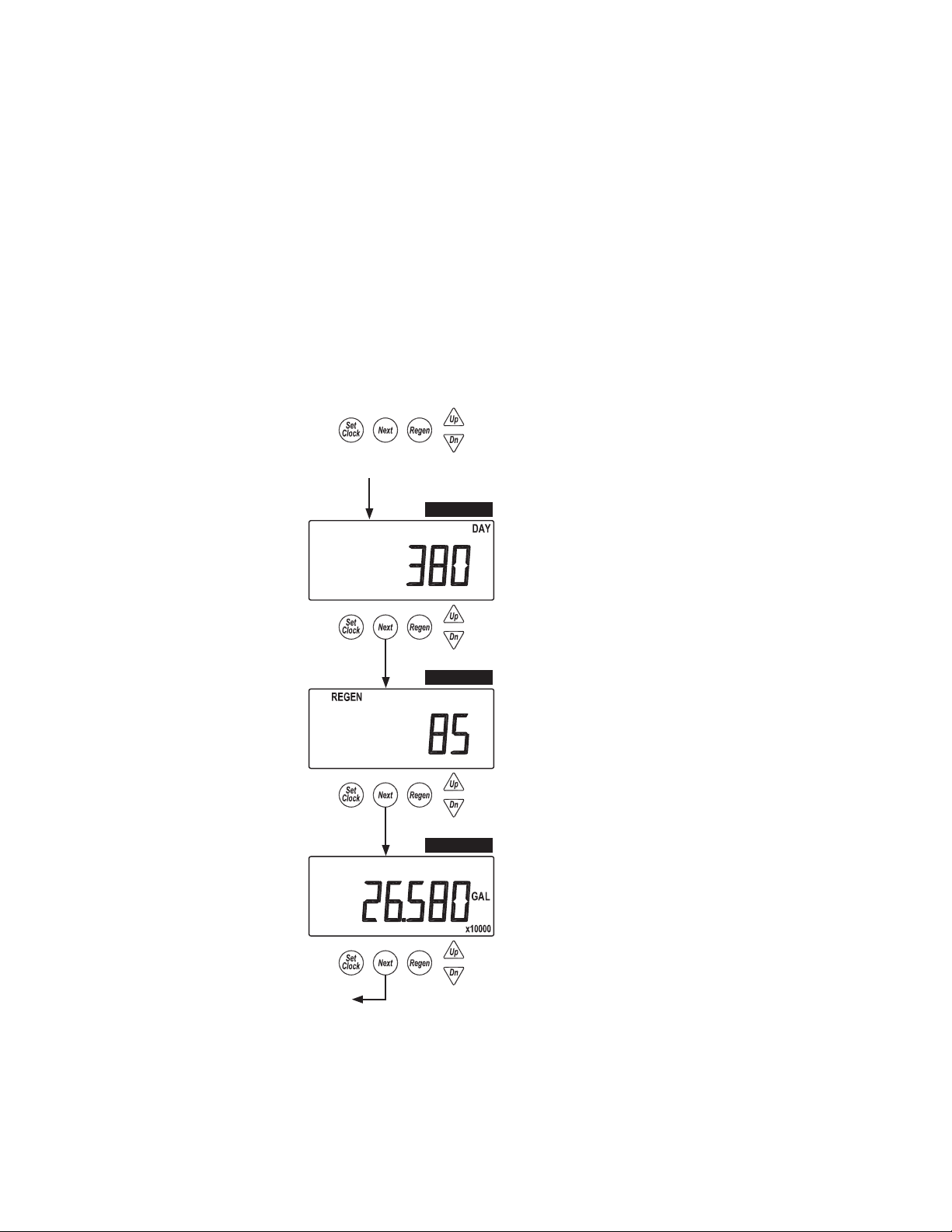
• Maximum ow rate and hour it occurred
• Maximum ow rate per unit by hour and
day it occurred
• Total volume through the unit since it was
installed
All Diagnostic History screens are resettable
with the History Reset sequence while in the
Diagnostics1 screen. Holding the Set Clock
and Regen buttons for >3 seconds initiates a
totalizer or history reset.
4
Page 5
H200/H200HF Diagnostic and History Screens provide the
DIAGNOSTIC 5
DIAGNOSTIC 6
DIAGNOSTIC 7
DIAGNOSTIC 7-B
WS2H Control Valve Manual Page 21
Diagnostic Screens (continued)
DIAGNOSTICS 5
Maximum fl ow rate
for the last 28 days.
Max fl ow rate of the day
DIAGNOSTICS 5-B
Hourly history of maximum
fl ow rate. Use the UP and
DOWN arrow to select the
hours of the day from screen 5.
Max fl ow within the selected hour
DIAGNOSTICS 6
Total volume through the unit.
DIAGNOSTICS 7
System totalizer for the last
63 days. Only displays in a
master unit.
System use for that day
DIAGNOSTICS 7-B
Hourly system totalizer. Use
the UP and DOWN arrow to
select the hour of the day from
screen 7.
Total system fl ow for the selected hour
Simultaneously press
UP and DOWN.
Automatically Toggles
Automatically Toggles
Automatically Toggles
Simultaneously press
UP and DOWN.
Return To
Normal Operation
Automatically Toggles
Return To
Normal Operation
Diagnostics 7
DIAGNOSTIC 5-B
Diagnostics 5
water treatment operator with a wealth of information.
5
Page 6
H200/H200HF Diagnostic and History Screens provide the
HISTORY 1
HISTORY 2
HISTORY 3
Page 22 WS2H Control Valve Manual
Valve History
Returns to normal operation after 5 minutes.
Accessed by pressing UP and DOWN simultaneously
for >3 seconds, then by pressing UP and DOWN
simultaneously again for >3 seconds.
HISTORY 1
Total days since startup.
Time only accumulates while
the unit is plugged in.
HISTORY 2
Total regenerations since startup.
HISTORY 3
Total volume since startup.
Return To
Normal Operation
Non-Resettable
water treatment operator with a wealth of information.
Valve History Screens
• Total days in operation
• Total regenerations since start-up
• Total volume of treated water
Returns to normal operation after 5 minutes. Non-Resettable.
6
Page 7

Modes of Regeneration
Time Clock - 7 or 28 day calendar clock shall initiate regeneration at a pre-set time of day.
Parallel Individual Meters - All units are in service at the same time with either delayed or immediate re-
generation. A lockout feature or offsetting time of regeneration prevents more than one unit to regenerate
at a time. Units may use either a xed or variable reserve for operation.
This is used where the ow rate of one unit is not enough and there is sufcient down time for conditioned
water to allow one unit to regenerate and the additional unit(s) to handle the ow rates during the regen-
eration time of the other unit, during off peak times.
Alternating Systems - This is the most efcient type of system in terms of maximizing operating costs for
salt and water as it uses up all of the available capacity prior to regeneration.
Alternating One Meter - Twin units, one meter. When all of the available capacity is used the unit on
stand-by will come on line and the unit in service will go into regeneration. Regeneration may occur immediate or during preset windows of time. Note: H200 Series have built-in internal meters on each unit.
Alternating Individual Meters - Twin, tri-plex or four-plex designs. One unit is always in service and the
remaining units are either in service, stand-by or regeneration. Only one unit may regenerate at a time.
Regeneration will occur immediately when one unit reaches exhaustion.
Demand Recall - Each unit has its own meter and only the primary unit is in service "on line". As the gpm
ow rate increases past a pre-set set point the second unit will come on line. If the ow rate increases
beyond the second pre-set set point and you have a tri-plex or four-plex system a third unit will come on
line, and should the ow rate increase beyond a third pre-set set point a fourth unit will come on line with
a four-plex system. As the ow rate decreases, units will go back on stand-by accordingly. When the primary unit goes into regeneration the next unit in sequence becomes the primary unit. Multiple set-points
are multiples of the rst set point. Example: 50, 100 & 150 GPM.
This is used where the ow rate for peak gpm usage may occur randomly such as a process application for CIP at shift change or where the supply xture counts for plumbing code requirements for certain
types of applications more than likely will never occur, yet they need to meet plumbing code requirements
for schools, ofce buildings, medical complex's . . . etc. In these types of applications the system may
very well function as an alternating design most of the time.
System Designs Single Twin Tri-Plex Four-Plex
Time Clock X X X X
Variable Reserve X X X X
Parallel, Individual Meters X X X
Demand Recall X X X
Alternating, One Meter X
Alternating Individual Meters
X X X
Meter Initiated Options:
Immediate - Regeneration shall occur immediately when the unit reaches exhaustion, zero gallons remaining
Delayed - Regeneration occurs during off peak usage with a xed reserve capacity
Variable Reserve - System automatically adjusts to changing water usage patterns and adjusts the reserve
capacity accordingly by day of the week. Regeneration occurs on a delayed basis.
.
7
Page 8
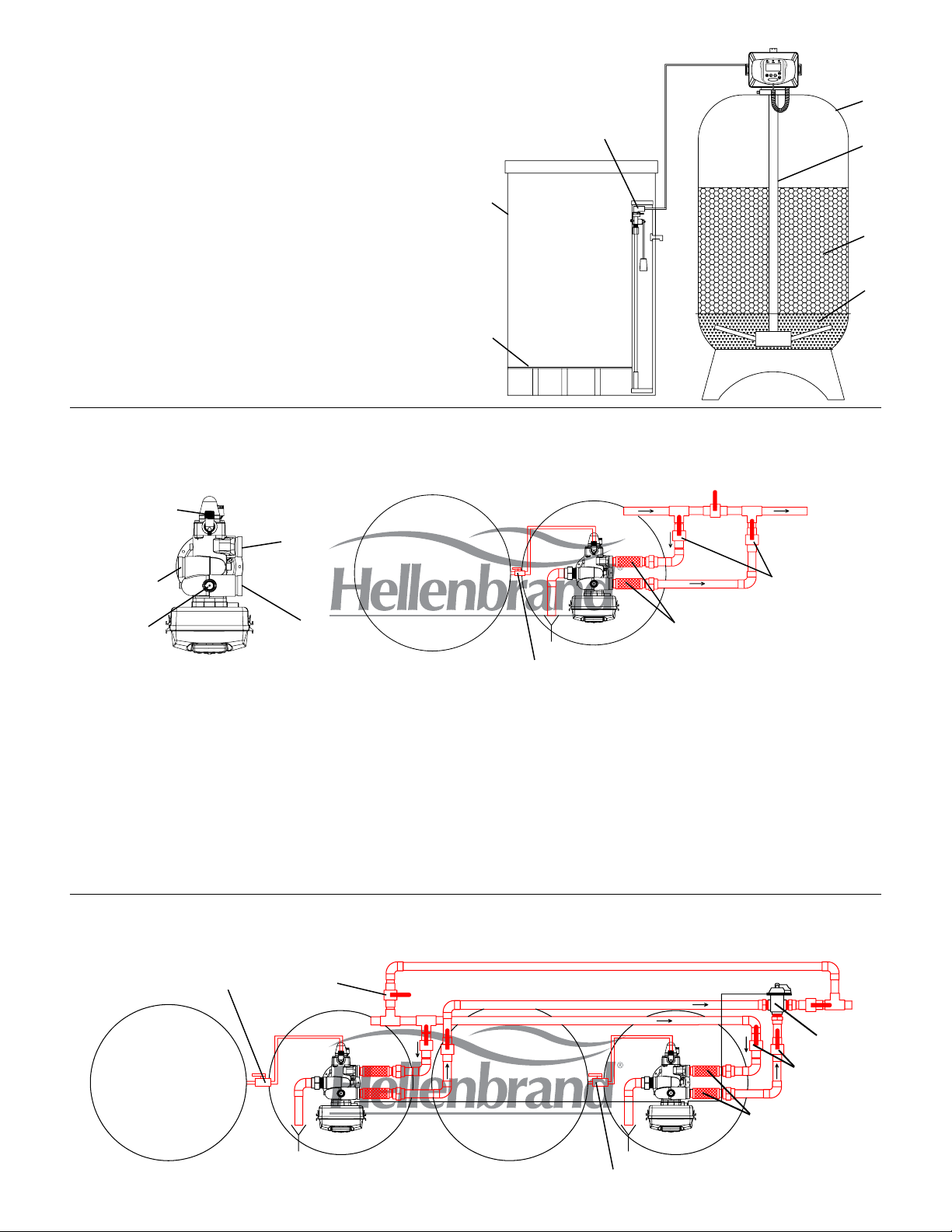
H200 Series
A. MINERAL TANK: Fiberglass tank with Polyethylene Inner
Shell and Fiberglass Roving Manufactured to Operate at
150 psi. NSF Approved.
B. DISTRIBUTOR SYSTEM: Two-Inch Hub & Lateral Dis-
tributor for Maximum Service Flow and Minimal Pressure
Loss.
C. MINERAL: High Capacity Ion Exchange Resin. Uniform
and stable beads assure long life, high salt efciency, and
maximum hardness removal.
D. UNDERBEDDING: Multi-Layered Gravel Underbedding
assures full usage of mineral bed and allows for a smooth
and constant water ow for service and regeneration.
E. BRINE TANK: Rotationally Molded Polyethylene with
Dust-Tight Cover.
F. GRID PLATE: Grid plate allows for dry salt storage. Avail-
able in various sizes and heights.
G. OPTIONAL SAFETY BRINE VALVE: Acts as a Secondary
Shut-Off for Timed Brine and may be used as a Primary
Shut-Off without Timed Brine.
E
F
G
H200 Typical Single Tank Installation-Top Mount
Bypass Valve
1" MNPT
Brine Line
2” FNPT Inlet &
2.5” Victaulic
Inlet
A
B
C
D
Figure 1
Outlet
2” FNPT Drain &
2.5” Victaulic
Internal Meter
2” FNPT Outlet &
2.5” Victaulic
Brine Tank
Shut-Off Valve
Isolation Valves
Flex Connectors
Figure 2
NOTE:
System connections to the tank must accommodate longitudinal movement between side, top and bottom
openings, exibility in piping or ex connectors are recommended.
Red colored piping, ttings, and connectors are for reference only and are not included. Must be furnished
by others.
Union type connectors are recommended on the inlet and outlet connections.
1" Brine Line must be hard-piped, secured and supported for proper operation. CPVC or Schedule 80 PVC
recommended.
H200 Twin Alternating Tank Installation - Top Mount
Shut-Off Valve
Bypass Valve
Inlet
MAV Valve*
Outlet
Brine Tank(s)
See NOTE Figure 2
MAV = Motorized Alternating Valve.
Isolation Valves
Brine Tank(s)
Flex Connectors
Figure 3
Shut-Off Valve
8
Page 9
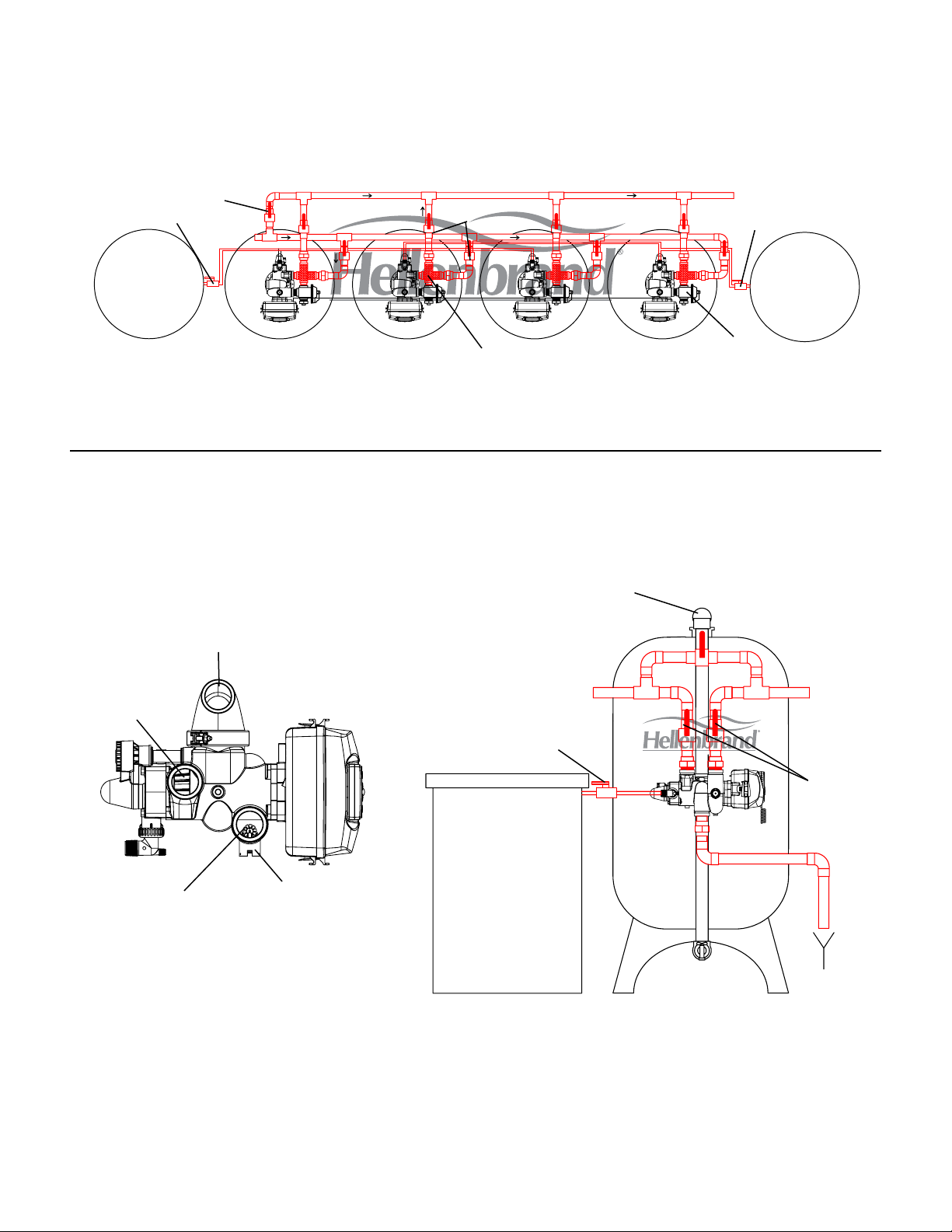
H200 Twin/Triplex/Fourplex Installation Top-Mount First-in, Last-Out Piping Arrangement.
"MAV" Shown for demand recall. Four Plex shown for reference only.
Bypass Valve
Shut-Off Valve
Inlet
Brine Tank(s)
Isolation Valves
Flex Connectors
See NOTE Figure 5
MAV = Motorized Alternating Valve.
H200 Single Installation - Side Mount
Sidemount
Adapter Base
Outlet
Shut-Off Valve
Brine Tank(s)
MAV Valve
Figure 4
Bypass Valve
2” FNPT Inlet &
2.5” Victaulic
Brine Line
1" MNPT
2” FNPT Outlet &
Shut-Off Valve
Brine Tank
Internal Meter
2.5” Victaulic
Inlet
Isolation
NOTE:
System connections to the tank must accommodate longitudinal movement between side, top and bot-
tom openings, exibility in piping or ex connectors are recommended.
Red colored piping, ttings, and connectors are for reference only and are not included. Must be fur-
nished by others.
Union type connectors are recommended on the inlet and outlet connections.
Outlet
Valves
Figure 5
1" Brine Line must be hard-piped, secured and supported for proper operation. CPVC or Schedule 80 PVC
recommended.
MAV = Motorized Alternating Valve.
9
Page 10
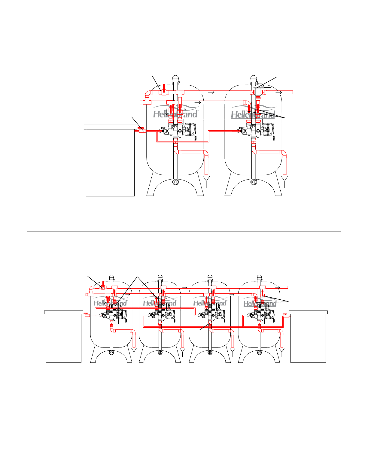
H200 Twin Alternating - Side Mount
Shut-Off Valve
Brine Tank
See NOTE Figure 7
MAV = Motorized Alternating Valve.
Bypass Valve
Inlet
MAV Valve
Outlet
Isolation
Valves
Figure 6
H200 Twin/Triplex/Fourplex Installation - Side Mount
First-in, Last-Out Piping Arrangement.
Bypass Valve
Inlet
Brine Tank(s)
NOTE:
System connections to the tank must accommodate longitudinal movement between side, top and bot-
tom openings, exibility in piping or ex connectors are recommended.
Red colored piping, ttings, and connectors are for reference only and are not included. Must be fur-
nished by others.
MAV Valves
DLFC
Outlet
Isolation
Valves
Brine Tank(s)
Figure 7
Union type connectors are recommended on the inlet and outlet connections.
1" Brine Line must be hard-piped, secured and supported for proper operation. CPVC or Schedule 80 PVC
recommended.
MAV = Motorized Alternating Valve.
10
Page 11
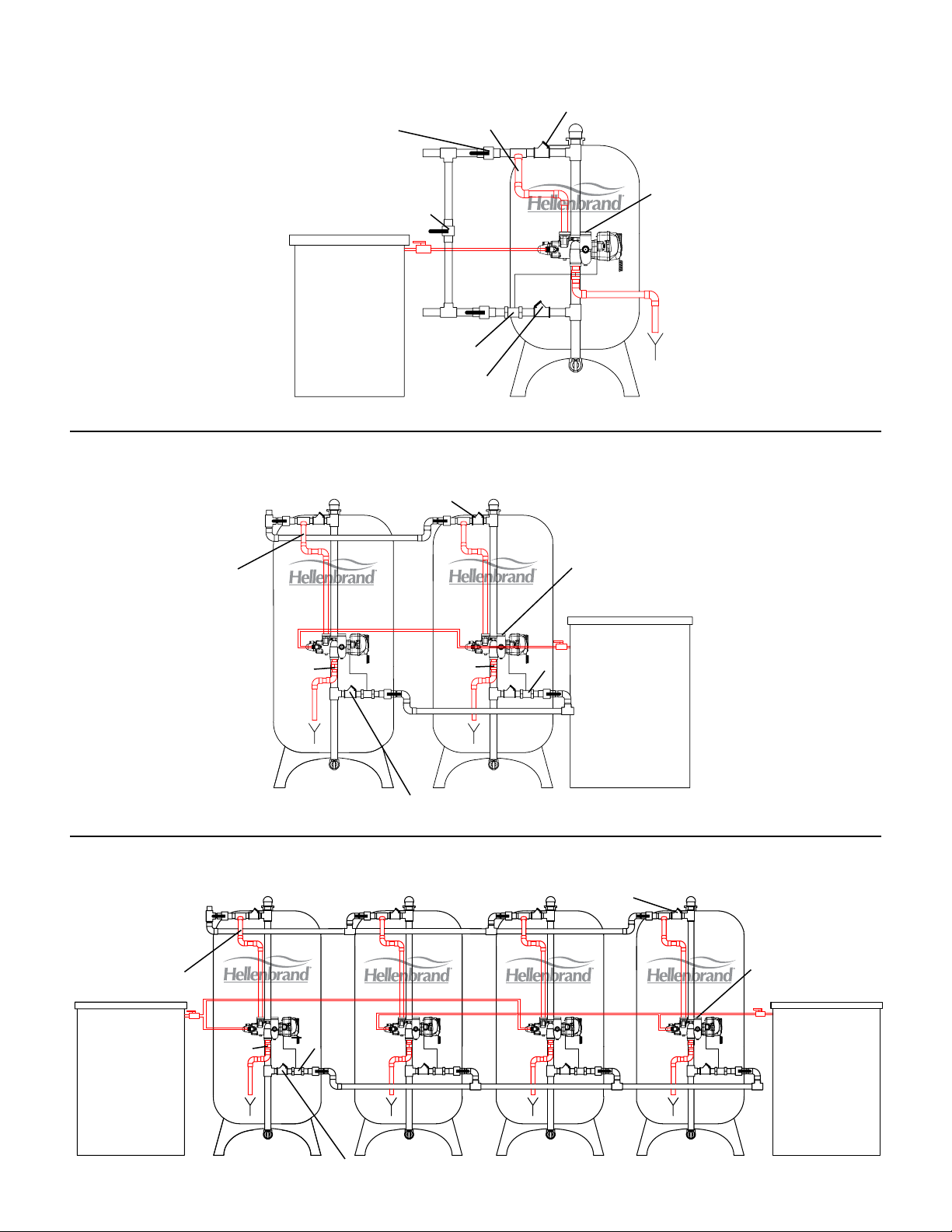
H200 HF Single Tank Installation
Pipe is on
Isolation Valve
Inlet
Bypass Valve
Brine Tank
an angle
Outlet
Meter
High Flow
Service Valve
Outlet is
Plugged
See NOTE Figure 7
1
Air or water operated
High Flow
Service Valve
1
H200 HF Twin Alternating Installation
High Flow
Service Valve
High Flow
Service Valve
MeterDLFC
1
Pipe is on
an angle
See NOTE Figure 7
1
Air or water operated
Inlet
DLFC
Figure 8
Valve outlet is
plugged
Brine Tank
Outlet
Figure 9
H200 HF Triplex/Fourplex Installation
Inlet
Pipe is on
an angle
Brine Tank(s)
See NOTE Figure 7
1
Air or water operated
DLFC
Meter
High Flow
Service Valve
1
High Flow
Service Valve
Valve outlet is
plugged
Brine Tank(s)
Outlet
Figure 10
11
Page 12
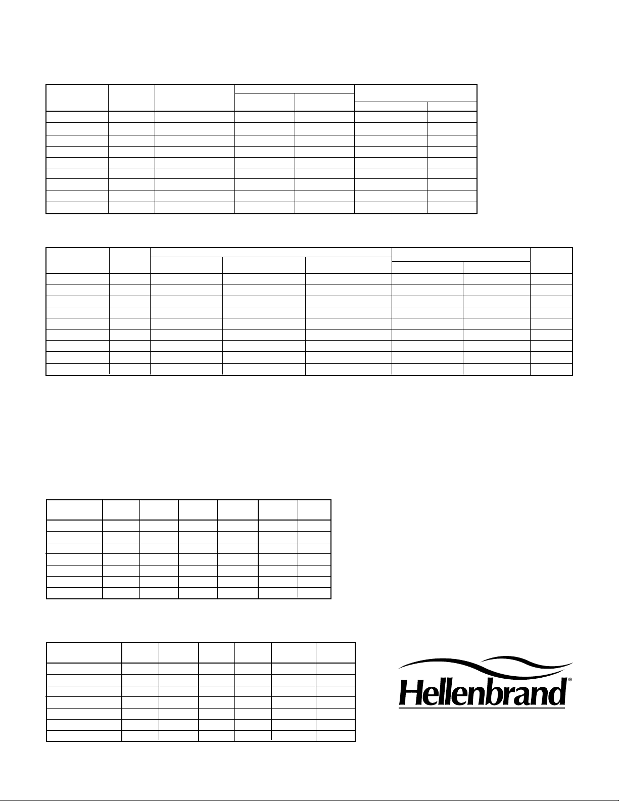
H200 Physical Specications
Mineral tank sizes shown are with polyglass tanks.
RECOMMENDED BRINE TANK APPROXIMATE
PIPE SIZE MINERAL TANK SIZE
MODEL (INCHES) (INCHES) (INCHES) ( LBS) SINGLE TWIN
H200-240 2 24 X 72 24 X 50 715 674 1325
H200-300-24 2 24 X 72 24 X 50 715 776 1529
H200-300-30 2 30 X 72 30 X 50 1,110 1059 2064
H200-450-30 2 30 X 72 39 X 48 2,030 1333 2593
H200-450-36 2 36 X 72 39 X 48 2,030 1393 2653
H200-600 2 36 X 72 39 X 48 1,640 1751 3426
H200-750 2 42 X 72 42 X 60 2,580 2535 4954
H200-900 2 42 X 72 50 X 60 4,130 2922 5750
H200-1200 2 48 X 72 50 X 60 4,130 3600 6900
SALT STORAGE
SHIPPING WEIGHT-TOP MOUNT
H200 Capacity Ratings
RATED CAPACITY FLOW RATES (gpm)
RESIN LOW SALT MEDIUM SALT HIGH SALT BKW
MODEL CU.FT. GRAINS/LBS GRAINS/LBS GRAINS/LBS 15 PSI 25 PSI GPM
H200-240 8 152,000/48 224,000/80 256,000/120 77 100 12
H200-300-24 10 190,000/60 280,000/100 320,000/150 75 97 12
H200-300-30 10 190,000/60 280,000/100 320,000/150 92 120 20
H200-450-30 15 285,000/90 420,000/150 480,000/225 88 113 20
H200-450-36 15 285,000/90 420,000/150 480,000/225 100 130 30
H200-600 20 380,000/120 560,000/200 640,000/300 97 126 30
H200-750 25 475,000/150 700,000/250 800,000/375 106 137 40
H200-900 30 570,000/180 840,000/300 960,000/450 104 130 40
H200-1200 40 760,000/240 1,120,000/400 1,280,000/600 105 135 50
1. Steel tank design congurations available up through 60” tank diameters. Consult factory for details.
OPERATING CONDITIONS
1. Water Pressure 30 - 100 psi.
2. Water temperature is not to exceed 110°F and the unit cannot be subject to freezing conditions. Consult factory for higher water temperature applications.
3. Limit of 2 ppm of Ferrous Iron. Add 3 grains per gallon of hardness for each ppm of iron present.
4. Flex connectors and vacuum breakers are required when using the PolyGlass Composite mineral tanks.
5. Backwash ow rates are calculated at 4 gpm per sq. ft. of bed area and rounded off based on 50ºF water temperature.
6. Refer to Hellenbrand Bulletin 2050 “Flow Rates and Soft Water Quality (Hardness Leakage) if your application requires that levels of hardness leakage do not exceed “x”.
H200 Series Top Mount Dimensions
SYSTEM OUTLET INLET DRAIN MINERAL BRINE
MODEL HEIGHT HEIGHTS HEIGHTS HEIGHTS TANK TANK
H200-300 89.4 86.7 83.1 85.4 24x72 24x50
H200-300-30
H200-450 86.2 83.5 79.9 82.2 30x72 39x48
H200-600 87.2 84.5 80.9 83.2 36x72 39x48
H200-750 104.5 101.8 98.2 100.5 42x72 42x60
H200-900 104.5 101.8 98.2 100.5 42x72 50x60
H200-1200 104.5 101.8 98.2 100.5 48x72 50x60
86.2 83.5 79.9 82.2 30x72 30x50
H200 Series Side Mount Dimensions
SYSTEM OUTLET INLET DRAIN MINERAL BRINE
MODEL HEIGHT HEIGHTS HEIGHTS HEIGHTS TANK TANK
H200-300-SM 95.6 54.6 51 53.3 24x72 24x50
H200-300-30-SM
H200-450-SM 94.6 54.6 51 53.3 30x72 39x48
H200-600-SM 95.3 54.6 51 53.3 36x72 39x48
H200-750-SM 100.9 54.6 51 53.3 42x72 42x60
H200-900-SM 100.9 54.6 51 53.3 42x72 50x60
H200-1200-SM 100.9 54.6 51 53.3 48x72 50x60
All dimensions ±2” and are subject to change without notice. Use as reference only.
Call factory for optional tank & dimensional congurations.
Product Improvement designs are subject to change without notice.
94.6 54.6 51 53.3 30x72 30x50
HELLENBRAND, INC.
(800) 626-1417
www.hellenbrand.com
12
Page 13
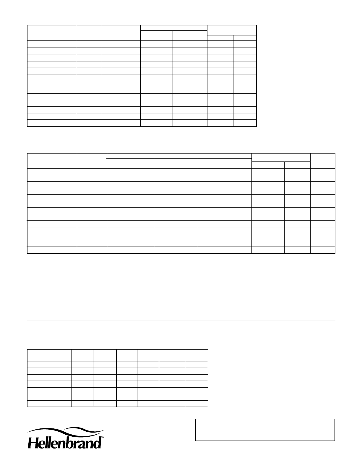
H200HF Physical Specications
BRINE TANK APPROXIMATE
PIPE SIZE MINERAL TANK SIZE
MODEL (INCHES) (INCHES) (INCHES) ( LBS) SINGLE TWIN
H200HF-300-24-3 3 24 X 72 30 X 50 1,110 1,200 2,300
H200HF-300-30-3 3 30 X 72 30 X 50 1,110 1,400 2,700
H200HF-450-30-3 3 30 X 72 39 X 48 2,030 1,700 3,300
H200HF-450-36-3 3 36 X 72 39 X 48 2,030 1,900 3,700
H200HF-600-3 3 36 X 72 39 X 48 1,640 2,100 4,100
H200HF-750-3 3 42 X 72 42 X 60 2,580 2,900 5,600
H200HF-900-3 3 42 X 72 50 X 60 4,130 3,350 6,400
H200HF-1200-3 3 48 X 72 50 X 60 4,130 3,850 7,500
H200HF-1200-4 4 48 X72 50 X 60 4,130 ––– –––
H200HF-1500-3 3 54 X 72* 60 X 64 4,000 ––– –––
H200HF-1500-4 4 54 X 72* 60 X 64 4,000 ––– –––
H200HF-1950-3 3 60 X 72* 72 X 54 4,800 ––– –––
H200HF-1950-4 4 60 X 72* 72 X 54 4,800 ––– –––
Mineral tank sizes shown are with polyglass tanks. (*denotes steel tanks)
SALT STORAGE
SHIPPING WEIGHT
H200HF Capacity Ratings
RATED CAPACITY FLOW RATES (gpm)
RESIN LOW SALT MEDIUM SALT HIGH SALT BKW
MODEL CU.FT. GRAINS/LBS GRAINS/LBS GRAINS/LBS 15 PSI 25 PSI GPM
H200HF-300-24-3 10 190,000/60 280,000/100 320,000/150 120 170 12
H200HF-300-30-3 10 190,000/60 280,000/100 320,000/150 175 225 20
H200HF-450-30-3 15 285,000/90 420,000/150 480,000/225 158 212 20
H200HF-450-36-3 15 285,000/90 420,000/150 480,000/225 200 278 30
H200HF-600-3 20 380,000/120 560,000/200 640,000/300 189 257 30
H200HF-750-3 25 475,000/150 700,000/250 800,000/375 212 280 40
H200F-900-3 30 570,000/180 840,000/300 960,000/450 200 268 50
H200F-1200-3 40 760,000/240 1,120,000/400 1,280,000/600 213 280 70
H200HF-1200-4 40 760,000/240 1,120,000/400 1,280,000/600 310 445 70
H200HF-1500-3 50 950,000/300 1,400,000/500 1,600,000/750 225 307 90
H200HF-1500-4 50 950,000/300 1,400,000/500 1,600,000/750 340 495 90
H200HF-1950-3 65 1,235,000/390 1,820,000/650 2,080,000/975 235 325 110
H200HF-1950-4 65 1,235,000/390 1,820,000/650 2,080,000/975 445 650 110
1. H200HF-300-24-34 through H200HF-1200-4 are shown with berglass mineral tanks. All of these are also available with steel tanks.
2. H200HF-1500-3 through H200HF-1950-4 are available with steel tanks.
OPERATING CONDITIONS
1. Water Pressure 30 - 100 psi.
2. Water temperature is not to exceed 110°F and the unit cannot be subject to freezing conditions. Consult factory for higher water temperature
applications.
3. Limit of 2 ppm of Ferrous Iron. Add 3 grains per gallon of hardness for each ppm of iron present.
4. Flex connectors and vacuum breakers are required when using the PolyGlass Composite mineral tanks.
5. Backwash ow rates are calculated at 4 gpm per sq. ft. of bed area and rounded off based on 50ºF water temperature.
6.
Refer to Hellenbrand Bulletin 2050 “Flow Rates and Soft Water Quality (Hardness Leakage) if your application requires that levels of hardness
leakage do not exceed “x”.
H200HF Series Side Mount Dimensions-Fiberglass Tanks
SYSTEM OUTLET INLET DRAIN MINERAL BRINE
MODEL HEIGHT HEIGHTS HEIGHTS HEIGHTS TANK TANK
H200HF-300 92.8 17 85.5 -- 24x72 24x50
H200HF-300-30
H200HF-450 95.6 17 85.5 -- 30x72 39x48
H200HF-600 96.3 17 85.5 -- 36x72 39x48
H200HF-750 101.9 17 85.5 -- 42x72 42x60
H200HF-900 101.9 17 85.5 -- 42x72 50x60
H200HF-1200 100.9 17 85.5 -- 48x72 50x60
95.6 17 85.5 -- 30x72 30x50
HELLENBRAND, INC.
(800) 626-1417
www.hellenbrand.com
All dimensions ±1” and are subject to change without
notice. Use as reference only.
Call factory for optional tank & dimensional congurations.
Product Improvement designs are subject to change
without notice.
HELLENBRAND WARRANTY
Go to www.hellenbrand.com for warranty details.
2/10-LBRY
 Loading...