

Hell Bent Steel Dodge Ram Adjustable Upper Control Arms 2000-2009 User Manual
HELL BENT STEEL - INSTALLATION INSTRUCTIONS
PN: 194-2000-001 FOR 2000-2009 DODGE RAM: FRONT UPPER CONTROL ARM
Pre-Installation Warnings:
Before installing this product on your vehicle, thoroughly read and
understand these instructions and the associated warnings.
Failure to properly follow all instructions and heed all warnings may
result in major property damage and/or serious bodily injury or death.
Test drive the vehicle to verify that it does not exhibit any uncommon
sounds or vibrations.
Inspect this product and all of its associated parts. Compare
the parts to those listed in these instructions. If any parts are missing
or damaged, promptly call and notify us at 877.731.7911. Do not
substitute any part or fastener from any other source. If you desire to
return the vehicle to stock, make sure to save all the original
components.
Installation Warnings:
WARNING: ONLY A CERTIFIED MECHANIC SHOULD
INSTALL THIS PRODUCT.
The OEM manual should be used at all times as a reference guide. The
person installing t h is pr o du ct should wear safety glasses and any other
personal protection items needed at all times. Failure to properly install
this product may result in serious bodily injury or death.
Maintenance Warnings:
It is your responsibility to re-torque and/or inspect the integrity of the
thread lock (where applicable) of all mounting fasteners after the first
100 miles, and every 3000 miles thereafter or after heavy use.
Failure to follow these steps could allow fasteners to come
loose and cause serious damage, bodily injury, or death.
Have your vehicle’s al ignment checked every 6 mon t h s.
Use Warnings:
DRIVE SAFELY! Avoid abrupt maneuvers such as sudden sharp turns
which could cause a roll over, resulting in serious injury or death.
You are solely responsible for any and all misuse, abuse,
improper installation, and/or improper maintenance of
this product and your vehicle.
After installing this product, drive with extreme caution, particularly
until you become familiar with how the vehicle handles. Slower speeds
may be required to maintain control.
Do not engage in any conduct that would void your vehicle’s factory
warranty, such as jumping the vehicle, driving the vehicle in excess of
payload towing restri cti ons, off-road racing, rock crawling, etc. Always
wear a seat belt.
Required tools:
18mm-24mm wrench / socket 1-1/2” wrench
Torque wrench 1-7/8” wrench
Torque Settings:
14mm mounting nut/bolt: 126 ft-lb
16mm OEM lower arm cam nut/bolt: 196 ft-lb
Assembly Instructions:
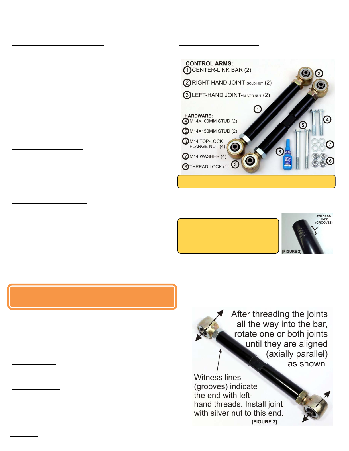
1. Unpack parts to ensure you have all components.
The kit includes the following:
NOTE: Depending on the year and model of your truck the items
may not appear the exact same as is pictured.
2. Assemble the center links and joints:
Install the nut on the joint. Thread the nut up the stem of the joint
until it reaches the bushing shoulder. Then, thread the joints all the
way into the arm, ensuring the nut stays snug at the bushing
shoulder.
NOTE: The witness line(s)* on the center
links indicate the end of the bar with lefthanded threads. *Depending on the year
and model of your truck, there will be 1,
2, 3, or 4 grooves. [FIGURE 2]
Install the joints with the left hand threads (silver nuts) on the
witness line end of the bars. Then install the joints with the right
hand threads (gold nuts) on the non-witness line end of the bars.
Repeat for all 4 joints. This process will make the arms as short as
possible. At this point the joints are probably not aligned properly.
Rotate one or both joints until they are aligned, making the arm look
like [FIGURE 3]. This will make the Hell Bent Steel arms
approximately the length of the OEM stock arms.
194-2000-1001
07/12
Control Arm Installation:
1. Park your vehicle on level ground. Block the rear tires of the
vehicle so the vehic le is st able and cannot roll. Safely lift the front of
the vehicle and support the axel with jack stands. Place jack stands
securely on both the driver and the passenger sides of the axel .
Remove the wheels from both sides.
NOTE: If you are ONLY replacing the upper control arms, you may not
need to remove the lower arms. If that's the case, you can skip step 2.
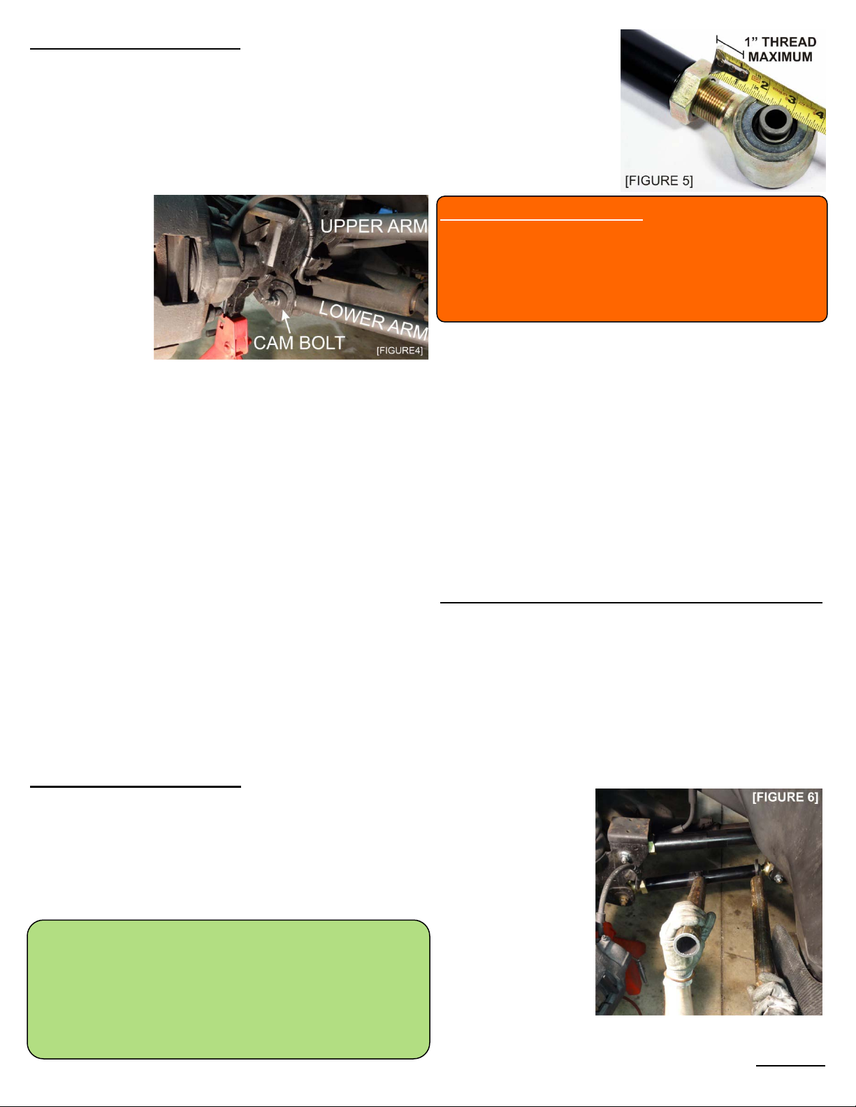
2. Remove lower
arm control arm
bolt. NOTE: Please
refer to installation
instructions for the
HBS adjustable
Lower Control
Arms or reference
your OEM manual
as a guide. If you
intend to retain
and re-use the cam bolt, place a line on the washer and frame with
chalk or marker to indicate the position of the cam bolt for
reinstallation later. Remove the front cam bolt. Remove rear mounting
bolt. This will release the lower arm completely.
3. Remove upper control arm. Remove both forward and rear
14mm mounting bolts. This will release the upper control arm so it
can be removed.
4. Insert new upper control arm in existing mounts. Ensure the
left-hand threaded joint (silver nut) is toward the rear of the vehicle
and the right-hand threaded joint (gold nut) is toward the front. Install
the rear joint first using the new HBS-provided 14mm X 150mm
hardware with the washer on the bolt head and the nut toward the
outside of the vehicle. Do not torque, finger tighten only. Repeat for
forward mounting bolt using the new HBS-provided 14mm X 100mm
hardware.
5. Refer to the instructions for installing the new low er cont ro l
arm in existing mounts. Follow the installation steps provided with
the HBS Adjustable Lower Control Arms.
6. Torque fasteners. Torque each fastener to specification.
7. Repeat steps 1 through 6 on the opposite side of the vehicle.
Control Arm Adjustment:
1. To adjust the arms: Park your vehicle on level ground. On your
new arms, rotate the center link so the arms are at their shortest
possible length. Begin rotating each arm (driver's side and passenger's
side) THE SAME NUMBER OF TURNS until the bottom of the shocks
are just forward of the top of the shock. There is no standard number
of turns that will accomplish this. Each truck may require a different
number of rotations to reach the proper position.
IMPORTANT: The number of rotations of the control arms should be
the same for both the driver's and passenger's side of the vehicle. This
is especially important if you are re-using your OEM cam bolts. If you
are replacing your cam bolts with the HBS CBE kit, your alignment
shop may adjust the rotation of each arm to achieve perfect alignment.
However, for your safety and the safety of your vehicle, have your
truck aligned immediately.
The HBS Adjustable
Control Arms have up
to 2" of adjustment
designed into them. It
is important to avoid
extending the length
beyond the designed
amount of adjustment.
UNDER NO CIRCUMSTANCES should the arms be adjusted
beyond the point where more than 1" of joint threads are
exposed! Extending the arms further can lead to critical
failure that could result in vehicle damage, personal injury,
and even death. Any adjustment beyond 1" of exposed
threads will void all warranties.
2. Have the vehicle aligned. It is necessary to apply thread-lock
to the jam nuts of each end joint of the new control arms to ensure
the nuts maintain position over time. However, once the thread lock
cures, you should never adjust the arms without cleaning off the old
thread lock and applying a new solution. It is required that the
vehicle be aligned before applying the thread lock for this reason.
3. Apply thread-lock. Once the adjustment has been reached and
the vehicle has been properly aligned, apply thread-lock.
When applying the thread lock you will want to ensure the solution
gets onto the threads that fit inside the center link as well as the jam
nut. Make a mark across the jam nuts onto the center link. You will
use this mark to ensure you return the parts to the same location.
Loosen the jam nuts. Record the number of turns you loosen the
nuts below. Then adjust the center link out, exposing more threads,
Record the number of turns below.
Driver's side: Passenger's side:_________
Front nut: __________ Front nut: __________
Rear nut: __________ Rear nut: __________
Center link: ________ Center link: ________
Generously apply the thread lock onto the exposed threads. Return
the center link and jam nuts to their previous location. The handling
cure time for the thread lock is 10-12 minutes. You will need to
tighten the jam nuts within that time frame. Full cure time is 24
hours.
9. Tighten the jam nuts. Put 1-1/2” wrench over the flat sections
on the center link to
keep it from twisting,
then place 1-7/8”
wrench onto the nut.
You will want to ensure
that the joints are
parallel within the
mounts, not twisted or
binding while you are
tightening the nuts. If
you are using wrenches
purchased from Hell
Bent Steel, do not use
more than 16-inch
cheater bar on either wrench.
194-2000-1001
07/12
 Loading...