

Hell Bent Steel 2006-2012 Dodge Ram 1500 4X4,4WD 2.5 Leveling User Manual
HELL BENT STEEL, INC - INSTALLATION INSTRUCTIONS
FRONT LEVELING SYSTEM FOR DODGE RAM 1500 2008.5-2010 4X4
P/N : 120-200-001, 120-250-001, 125-200-001, & 125-250-001
These instructions are available with larger color photos on our website at www.hellbentsteel.com
IMPORTANT NOTES:
Please read before beginning installation. OEM Manual should be used
as a reference.
It is highly recommended that a certified mechanic perform this
installation.
Read and understand all the instructions before beginning
installation.
Use Locktite® on all bolts associated with this installation.
Torque Specifications:
Shock Absorber-to-Lower Arm Nut and Bolt………….………….…..….. 155 ft-lbs
Stabilizer Bar-to-Link Nut ……..…………………………………………….……. 75 ft-lbs
Tie-Rod End Nut ……….……………………………………………………………. 45 ft-lbs
Upper Ball Joint Nut …………………..……………………………..……………… 50 ft-lbs
Upper Strut Mounting Nuts ……………………………………………………….. 45 ft-lbs
Wheel Lug Nut ………………………………………………………….……… 120-150 ft-lbs
If you desire to return the vehicle to stock, make sure to save all the
stock components.
WARNING: IT IS HIGHLY RECOMMENDED THAT A
CERTIFIED MECHANIC PERFORM
IMPORTANT CUSTOMER INFORMATION:
This vehicle’s reaction and handling characteristics may differ from that
of standard cars and/or trucks. Modifications to improve off road
performance may raise the vehicle’s intended center of gravity.
Extreme caution must be utilized when encountering driving conditions
that may cause vehicle imbalance or loss of control. DRIVE SAFELY!
Avoid abrupt maneuvers, such as sharp turns, which could cause a roll
over, resulting in serious injury or death.
It is the customer’s responsibility to make sure a re-torque is
performed on all hardware associated with this suspension system
after the first 100 miles. It is also the customer’s responsibility to do a
complete re-torque after every 1000 miles or after every off road use.
After the original installation, it is recommended to have the alignment
checked by a certified alignment technician that is experienced with
lifted vehicles. Also the alignment should be checked every 6 months
to ensure proper tracking, proper wear on tires and front-end
components. The responsibility for abuse, improper installation, or
improper suspension maintenance is solely that of the customer.
It is the responsibility of the customer or the mechanic to wear safety
glasses at all times when working with air tools.
BEFORE BEGINNING, Please read all of the instructions
carefully. Before installation begins, drive the vehicle and inspect it
to make sure that there are not any uncommon sounds or frame
damage.
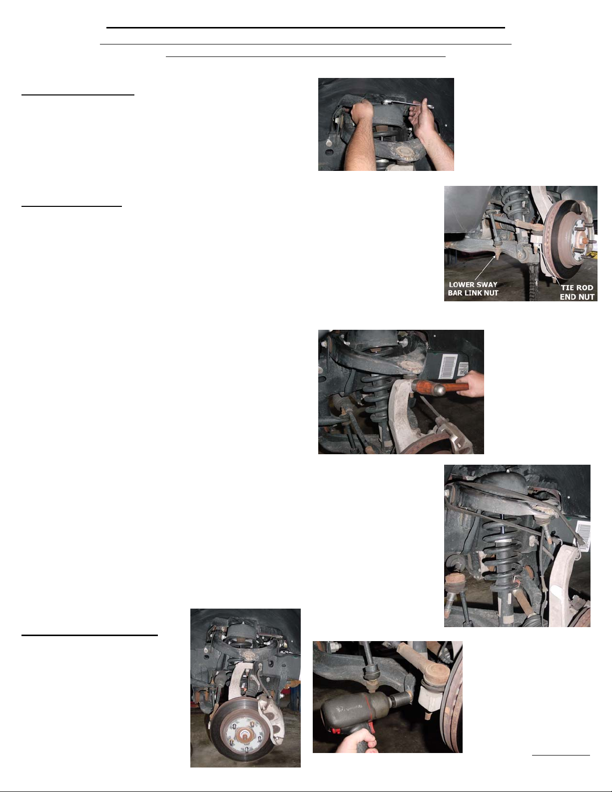
Front End Installation:
1. To begin installation, block the rear
tires of the vehicle so that the vehicle is
stable and can’t roll backwards. Safely lift
the front of the vehicle so that the front
wheels are off the ground. Support the
frame with jack stands. Place jack stands
on both the driver
and the passenger sides of the vehicle.
Next remove the wheels from both sides.
THIS INSTALLATION.
NOTICE:
2. Break loose the 3 upper strut
mount nuts with a 15-mm wrench
or socket. Remove the back two
nuts completely. Loosen but do
not remove the front nut.
3. Remove the lower sway bar
link from the bottom of the
control arm with an 18 mm
deep socket. Disconnect the
tie rod end nut with a 21 mm
socket. Using a ball peen
hammer or impact tool, hit the
steering knuckle (not the tie
rod) until the tie rod pops out.
If you use a tie rod pickle fork,
be careful not to cut the tie rod
boot. A severed tie rod boot will allow dirt and moisture to damage the
tie rod end.
5. Support the knuckle with a
bungee cord or safety wire so
not to overextend the CV axel
or stretch the brake hydraulic
hose.
6. Next remove the struts
lower bolt. Using a 24 mm
wrench, hold the nut and
remove the bolt with a 21 mm
socket. Now remove the third
nut from the upper strut
mount.
4. Remove the upper
ball joint nut with a 21
mm
socket. Use a
hammer to strike
the side of the
steering knuckle
until the upper control
arm pops out.
7. Pulling outward on the strut
assembly, you should be able
to clear the upper strut tower
and remove the strut
assembly.
120-000-1001
06/10
***PLEASE NOTICE***
In March of 2008 Dodge made a change to the strut of the Dodge Ram
1500 4X4 strut cap. Dodge deci ded to omit a 1/8” plate that was th ere in
the earlier models. See photos below.
Shown in Figures 1 and 2, is the 2006-Feb 2008 strut cap design.
FIG 1 FIG 2
Figure 3 shows the post March 2008 strut cap.
FIG 3
**Notice the absence of the plate over the rubber bushing.**
If your truck was manufactured after 2008 you should have received plates
with your kit. Please notice this upon install. If your truck does NOT have
the plate attached, use the 1/8” thick plate provided with the HBS spacers.
Place the plate on the strut cap BEFORE you fasten the spacer to the cap
as shown in Figures 4, 5, and 6. This must be done in order to secure
the rubber bushing in the strut cap.
FIG 6
FIG 4 FIG 5
*** If you have a 2006-2007 and your truck does NOT have the
plate attached, do NOT install the kit and please contact us at the
number above so that we can send you the plates needed***
8. Place the Hell Bent Steel
strut extension on the top of
the strut, hold the part up to
start the factory nuts onto the
factory studs.
* NOTE: Use the factory
nuts with the factory
studs*
9. Run down the factory nuts
snug with 15 mm end wrench.
Torque to OEM specs.
10. Place strut back into upper
strut mount. Tighten provided
nuts snug with wrench or
ratchet (after install, you will
torque to OEM specs).
Because of the shape of the HBS spacer, you will need
to rotate the strut assembly 180º
11. Use a pry bar and/or floor jack to position the lower control arm
and the strut assembly to reinstall the lower mounting bolt. Torque to
OEM specs.
12. Place a jack under
the lower control arm.
Raise the lower control
arm to reattach the ball
joint. A pry bar may be
used to hold the upper
control arm into
position. Torque the
ball joint nut to OEM
specs. Reattach the tie
rod end and torque to
OEM specs.
13. Repeat procedure on opposite side.
14. Reattach the sway bar. Torque to OEM specs.
15. Reattach the front wheels. Torque to OEM specs
16. Lower vehicle to ground and torque strut mounts to OEM specs.
17. HAVE THE VEHICLE ALIGNED. A certified alignment technician
that is experienced with lifted vehicles is recommended to perform the
alignment. Realignment is necessary to allow the suspension to settle to
its desired ride height (the wheels will be toed-in which will cause
excessive wear on your tires and the nose will sit higher than it should.)
**Adjust your head lights if necessary.**
PLEASE NOTE:
The 1-3/8" thick spacer gives you a total lift of 2.5". This is
due to the fact that when you extend the strut by 1-3/8" the
strut will be rotated to a slightly steeper angle. It is the
combination of extending the strut and the change in angle
that gives the total lift. For the same reason, the spacer in
the 2" kit measures 1-1/4".
If you have any questions please call our Tech Support toll
free at 1.877.731.7911
These instructions are available
in full color on our website www.hellbentsteel.com
120-000-1001
06/10
 Loading...