

Page 1
Warranty Statement
b
a
d
b
a
d
b
a
d
Congratulations! The product you have selected comes from HELLA – one of the world's
leading manufacturers of lighting products. The product comes with a 5 year warranty from
end user purchase covering faults in materials, components or workmanship.
In the unlikely event that you should experience a conrmed warranty related problem with your
purchase, HELLA will, at its discretion, either repair, replace or refund the purchase price of the
product.
Warranty services may be obtained by returning the product within the warranty period to the
HELLA dealer where the product was originally purchased.
This warranty is in addition to and does not preclude any other rights or remedies available to the
consumer under any local legislation related to the provision of goods or services.
Our goods come with guarantees that cannot be excluded under the Australian Consumer Law.
You are entitled to a replacement or refund for a major failure and for compensation for any other
reasonably foreseeable loss or damage. You are also entitled to have the goods repaired or replaced
if the goods fail to be of acceptable quality and the failure does not amount to a major failure.
This warranty does not cover:
1.) Claim/s as a result of normal wear and tear or of any modications and / or alterations to the product in any
shape or form.
2.) Claim/s as a result of non-compliance of the assembly, service and operating instructions and/or any unt or
improper use.
3.) Any expenses incurred in the process of making the claim.
Note: For lamps sold in Australia warranty services are provided by HELLA Australia Pty Ltd,
54-76 Southern Rd, Mentone VIC 3194. Customer Service 1800 061 729,
[email protected], www.hella.com/hella-au/21.html
For general comments about Hella marine products please contact us on E-mail at [email protected]
LED Degradation Caused by Service Life Conditions
The luminous intensity of LEDs gradually diminishes over time, even as electricity consumption
remains constant. The rate of decline in luminous intensity is linked to the current output owing
through the LEDs and their operating temperatures. Hella marine has evaluated the service life
conditions of NavLED® navigation lamps to ensure long term safety at sea and compliance with
international standards such as ABYC C-5:2021 & ISO 19009:2015.
For continued adherence to the light output criteria outlined in its certication, Hella marine suggests
replacing the NaviLED®PRO 3NM Masthead lamp once it has accumulated 25,000 hours of operation.
To determine if the service life threshold has been reached, you'll need an estimated annual usage
in hours along with the lamp's production date. The production date is engraved onto the front of the
lens in the following format:
DDMMYY_HHMMSS (Day/Month/Year_Hour/Minute/Second)
For instance, if a lamp with a production date of 140823_153520 is estimated to operate for 1500
hours annually, it's conceivable that the service life threshold will be reached after 16 years of usage
– approximately around 2039.
In the context of typical recreational boating standards, even with regular night sailing, it's unlikely
that the service life threshold will be reached. Additionally it is recommended that regular checks are
made during the service life of the lamp to ensure that there haven’t been any LED failures.
INSTRUCTION SHEET: NaviLED® PRO
3 Nautical Mile Masthead Lamp
for: 2LT 959 940-2xx
Hella marine LED navigation lamps oer many advantages over conventional bulb lamps.
Signicantly reduced power consumption, ultra long life and high tolerance to shock and vibration
make the LED lamps the ideal choice for the harsh marine environment.
Th e He l la ma r i ne Na vi L ED®PRO series are precision optical instruments, tested and type approved
to comply with international maritime regulations. They are covered by a 5 year warranty.
Material Description UV resistant lens, high impact resistant shroud
Minimum Visible Vistance 3 Nautical Miles
Vessel Size: Recreational vessels < 20m
Cable Pre-wired with 2.5m of twin core marine cable
Operating Voltage MultivoltTM 9-33V DC
Power Consumption < 2.5W (0.2A@ 12V / 0.1A @ 24V)
Degree of Protection IP 67 – Completely sealed
Weight 250g (including cable)
International Approvals IMO COL REG 72, ISO 19009:2015, EN 60945:2002
RINA Type Approval Certicate No. ELE118523PU
USCG 33 CFR 183.810, ABYC C-5
ABYC C-5 Tested by: Imanna Laboratory (Date: 1/08/2023)
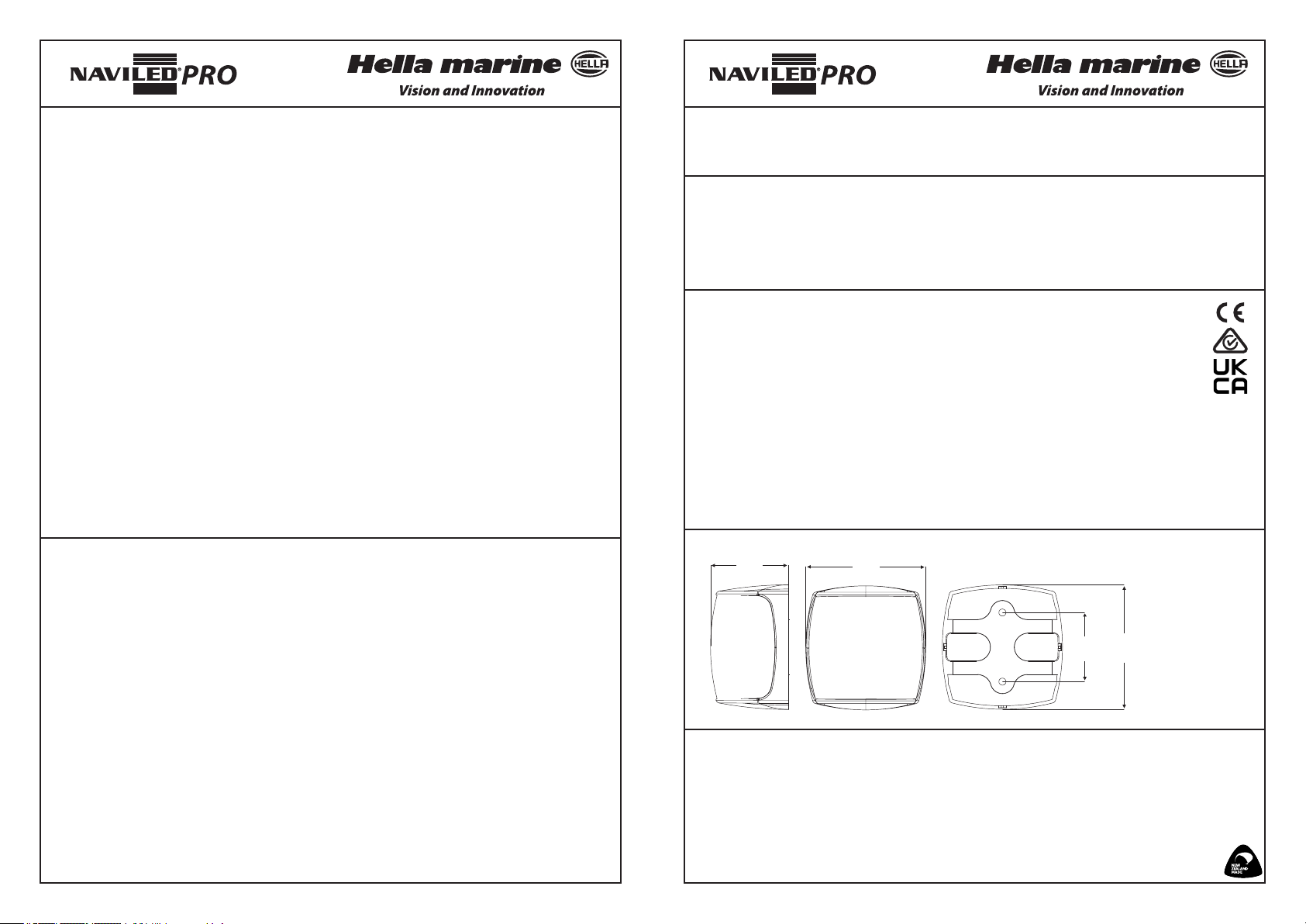
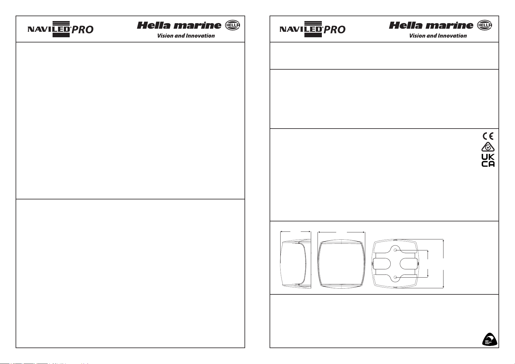
Dimensions
c
Dimensions
d
Electromagnetic Compatibility (EMC)
This LED lamp is an electronic device. The electrical circuits contain components that suppress
possible interference, both emission as well as susceptibility, to the limits prescribed in international
regulations.
Protection against damage due to voltage spikes
This lamp is protected against reverse polarity connection, positive voltage spikes up
to +500 volts and negative voltage spikes of up to 700 volts.
Designed and Manufactured in New Zealand
a = 87mm / 3.43”
b
b = 90mm / 3.54”
c = 57mm / 2.25”
d = 50mm / 1.97”
959 150-02 / 12.23
Page 2
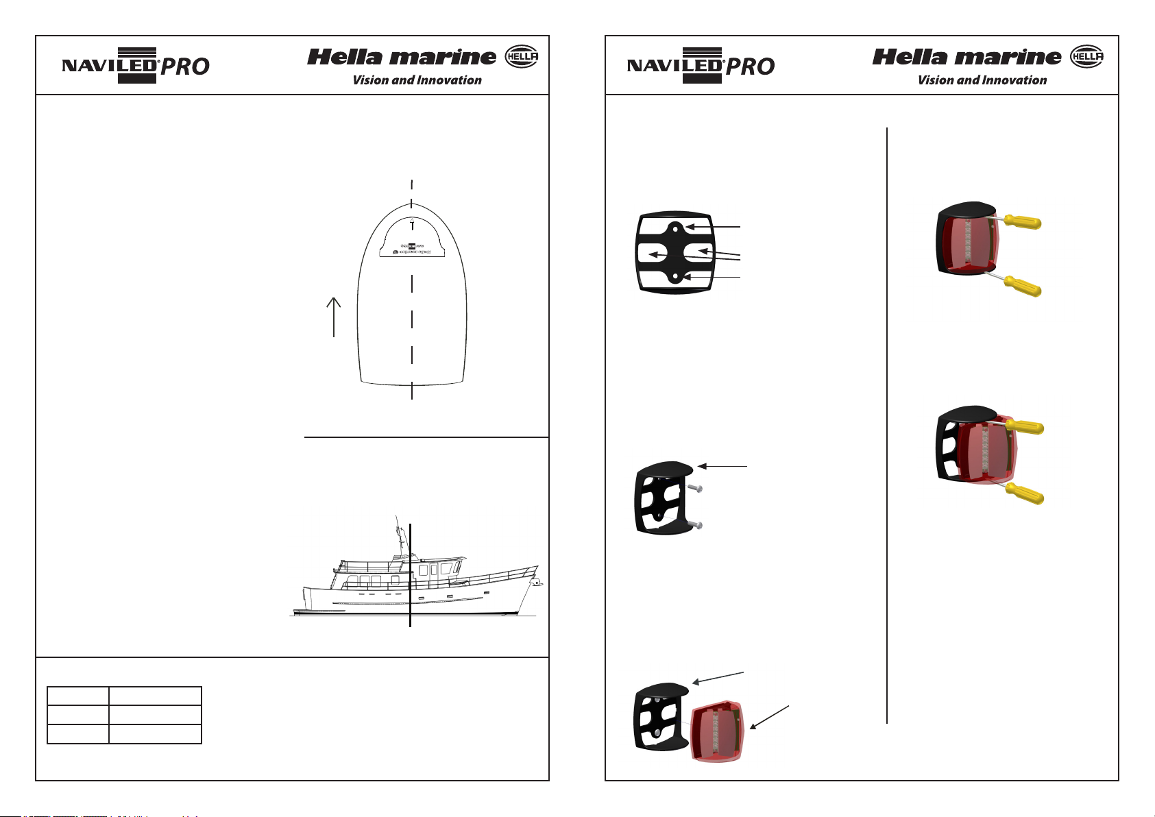
Lamp positioning
General recommendations
When the lamp is operating, the light should not
be obstructed or concealed by superstructures
or other objects.
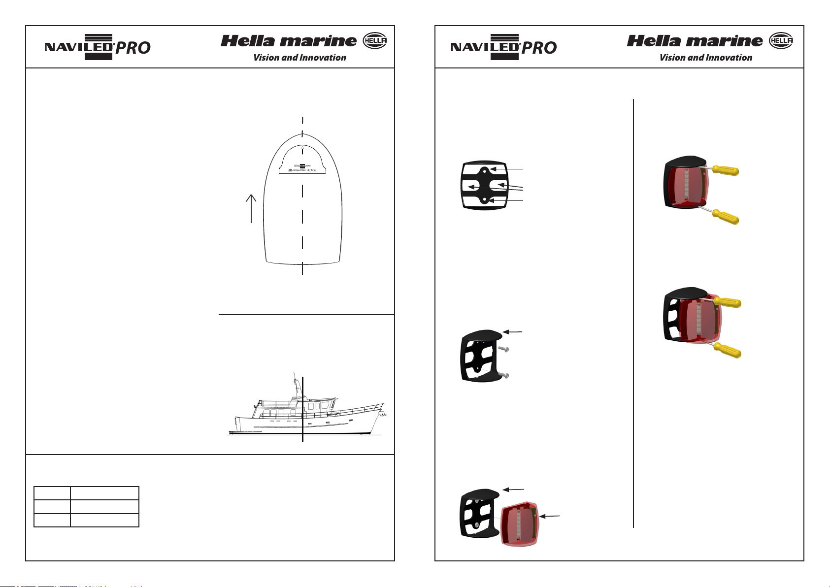
Fig. 1 Right angle to the vessel's centre line
Assembly
Step 1 – Make provision for the power cable
Use mounting shroud as a template to drill screw
holes and make provision for the cable.
Removal
Step 1
Carefully insert 2 screw drivers between
optic assembly and shroud.
Position in relation to vessels centre line
The masthead lamp must be positioned in a
vertical position and at a right angle to the
vessel's centre line with the signal direction
arrow pointing straight ahead (see Fig. 1).
Horizontal positioning
The light shall be displayed forward of
amidships, except on a boat less than 20 metres
in length, where the masthead lamp need not
be placed forward of amidships (see Fig. 2), but
must be placed as far forward as practicable
taking into account the vertical positioning
requirements above the gunwale or sidelights –
as described below.
Vertical positioning
On a powerboat
- over 20 metres in length: the masthead lamp
must be placed at a height above the hull of
not less than 6 metres. The height must be
more than the breadth of the hull, but no more
than 12 metres above the hull.
- between 12 and 20 metres in length: the
masthead lamp must be placed at a height
above the gunwale of not less than 2.5 metres.
- less than 12 metres in length: the masthead
lamp must be placed at least 1 metre higher
than the sidelights.
Note: Consideration for country specic rules
may be required.
Wiring Colour Coding
Colour Connect to
Black Negative (-ve)
Red Signal (+ve)
LED modules are polarity conscious. Reverse polarity will not
damage this product but will inhibit its function.
HELLA recommends wire connections be soldered, and heat
shrink tubing applied to seal the joint.
Note: Lamp must be protected by a fuse rated at 3 amperes
maximum.
2LT 959 940
Made in New Zealand
TOP
Top view
Fig. 2 Horizontal positioning
Amidship
Screw hole
Allow for cable
Screw hole
Step 2 – Mount the Shroud
2.1 Shroud must be installed with markings on
Step 2
Pull optic assembly out.
the top horizontal surface.
2.2 Arrow on top of shroud must point straight
ahead.
2.3 Fix shroud with two M5 or 10 gauge fasteners.
Markings on the top
Use marine grade
stainless steel fasteners
with a wide at head
(not included)
Step 3 – Insert the optic assembly
Note: Arrow on top of shroud and arrow on top of
optic assembly must point in the same direction.
3.1 Feed power cable through shroud
3.2 Push optic assembly into shroud
3.3 Connect power
Shroud
Optic Assembly
Note: Do not open. No servicable par ts
inside.
www.hellamarine.com
Page 3
Garantieerklärung
b
a
d
b
a
d
b
a
d
INSTALLATIONSANWEISUNG: NaviLED® PRO
Topplaterne mit 3 Seemeilen Tragweite
Herzlichen Glückwunsch! Das von Ihnen erworbene Qualitätsprodukt kommt von HELLA,
einem d er führend en Herste ller von Bel euchtung ssystemen w eltweit , und ist mi t einer Gara ntie
von 5 Jahren ausgestattet. Diese d eckt Fehler in Materialien, Komponenten und Verar beitung
ab und gilt ab Kaufdatum.
In dem unwahrscheinlichen Fall, dass ein Produkt tatsächlich fehlerhaft ist und ein Garantiefall
vorliegt, wird HELLA Ihr Produkt nach eigenem Ermessen reparieren, ersetzen oder den Kaufpreis
zurückerstatten.
Garantieleistungen können durch Rücksendung der Ware innerhalb der Garantiezeit an den HELLAHändler, bei dem das Produkt ursprünglich gekauft wurde, erhalten werden.
Diese Garantie gilt zusätzlich zu allen anderen Rechten oder Rechtsmitteln, die dem Verbraucher im
Rahmen einer lokalen Gesetzgebung in Bezug auf die Bereitstellung von Waren oder Dienstleistung
zur Verfügung stehen und schließt diese nicht aus.
Diese Garantie gilt nicht für:
1.) Ansprüche, die aus normalem Verschleiß des Produktes oder etwaigen Änderungen oder Modikationen am
Produkt in irgendeiner Form entstehen.
2 . ) An sp r üc he , di e a l s Fo lg e a us N ic ht e in h al tu n g d e r Mo nt a ge -, S er v i ce -, o de r Be d ie n un g sa n le it u ng od er du rc h
unsachgemäßen Gebrauch entstehen.
3.) Jegliche Kosten, die durch den Prozess der Inanspruchnahme der Garantie entstehen.
Bei Fragen zu HELLA-Produkten wenden Sie sich bitte an [email protected]
LED-Abbau durch Servicelebensbedingungen
Hella marine LED Navigationslaternen bieten erhebliche Vorteile gegenüber herkömmlichen Laternen
mit Glühlampen: Durch deutlich verringerte Leistungsaufnahme, extrem lange Lebensdauer und
Unempndlichkeit gegen Stöße und Vibrationen sind NaviLED®Pro LED Laternen ideal für hohe
Beanspruchungen im maritimen Einsatz.
Hella marine NaviLED®PRO Navigationslaternen sind optische Präzisionsinstrumente, typgeprüft nach
internationalen Standards. Sie sind mit einer Garantie von 5 Jahren ausgestattet.
Materialbeschreibung Lichtscheibe UV-resistent, stoßfestes Gehäuse
Tragweite 3 Seemeilen
Schislänge Sportboote < 20m
Kabel Vorverkabelt mit 2,5m zweiadrigem Marinekabel
Betriebsspannung MultivoltTM 9-33V DC
Leistungsaufnahme < 2,5W (0,2A @ 12V / 0,1A @ 24V)
Schutzgrad IP 67 – Hermetisch versiegelt
Gewicht 250g inklusive Kabel
Internationale Zulassungen IMO COL REG 72, ISO 19009:2015, EN 60945:2002
RINA Bauteilgenehmigung Nr. ELE118523PU
USCG 33 CFR 183.810, ABYC C-5
ABYC C-5 Gestestet von Imanna Laboratory (Datum 1/08/2023)
für: 2LT 959 940 -2xx
Die Lichtintensität von LEDs nimmt im Laufe der Zeit nach und nach ab, auch wenn der
Stromverbrauch konstant bleibt. Eine verminderte Lichtintensität hängt mit den Betriebstemperaturen
sowie dem Stromausgang zusammen, der durch die LEDs ießt. Hella Marine hat die Beständigkeit
der NavLED®-Navigationslaternen bewertet, um langfristige Sicherheit auf See und die Einhaltung
internationaler Standards wie ABYC C-5:2021 & ISO 19009:2015 zu gewährleisten.
Zur weiteren Einhaltung der in der Zertizierung festgelegten Lichtleistungskriterien empehlt Hella
Marine den Austausch der NaviLED® PRO 3NM Masthead-Laterne nach 25.000 Betriebsstunden. Um
festzustellen, ob die Lebensdauerschwelle erreicht wurde, benötigen Sie eine geschätzte jährliche
Nutzung in Stunden sowie das Produktionsdatum der Laterne. Das Produktionsdatum ist auf der
Vorderseite der Linse im folgenden Format eingraviert:
TTMMJJ_HHMMSS (Tag/Monat/Jahr_Stunde/Minute/Sekunde)
Wenn beispielsweise eine Laterne mit einem Produktionsdatum von 140823_153520 voraussichtlich
1500 Stunden pro Jahr betrieben wird, ist es denkbar, dass die Lebensdauerschwelle nach 16 Jahren
Nutzung - ungefähr um 2039 - erreicht wird.
Im Kontext der typischen Standards für Freizeitboote ist es auch bei regelmäßigem Nachtsegeln
unwahrscheinlich, dass die Lebensdauerschwelle erreicht wird. Zusätzlich wird empfohlen, während
der Lebensdauer der Lampe regelmäßige Kontrollen durchzuführen, um sicherzustellen, dass es
keine LED-Ausfälle gegeben hat.
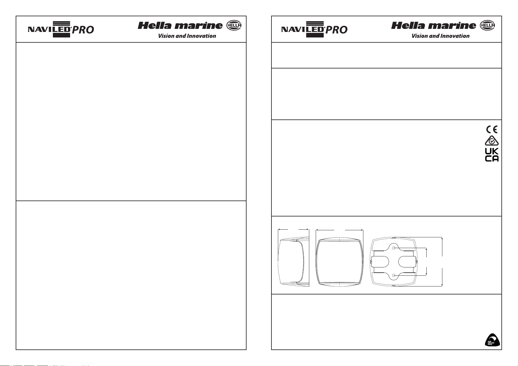
Abmessungen
c
Dimensions
d
Elektromagnetische Verträglichkeit (EMV)
Diese LED-Laterne ist ein elektronisches Gerät. Ihre integrierten Schaltkreise beinhalten Komponenten,
die Interferenzen (sowohl Emissionen als auch Anfälligkeit für Strahlung anderer Geräte) unterdrücken
und entsprechen internationalen Bestimmungen.
Schutz gegen Schäden durch Spannungsspitzen
Diese Laterne ist gegen Spannungsspitzen (bis +500 Volt) und Verpolung (bis -700 Volt)
geschützt.
Designed und hergestellt in New Zealand
a = 87mm / 3.43”
b
b = 90mm / 3.54”
c = 57mm / 2.25”
d = 50mm / 1.97”
Page 4
Positionierung der Laterne
Allgemeine Hinweise
Wenn die Laterne eingeschaltet ist, darf das
Licht nicht durch Aufbauten oder andere Objekte
behindert oder verdeckt werden.
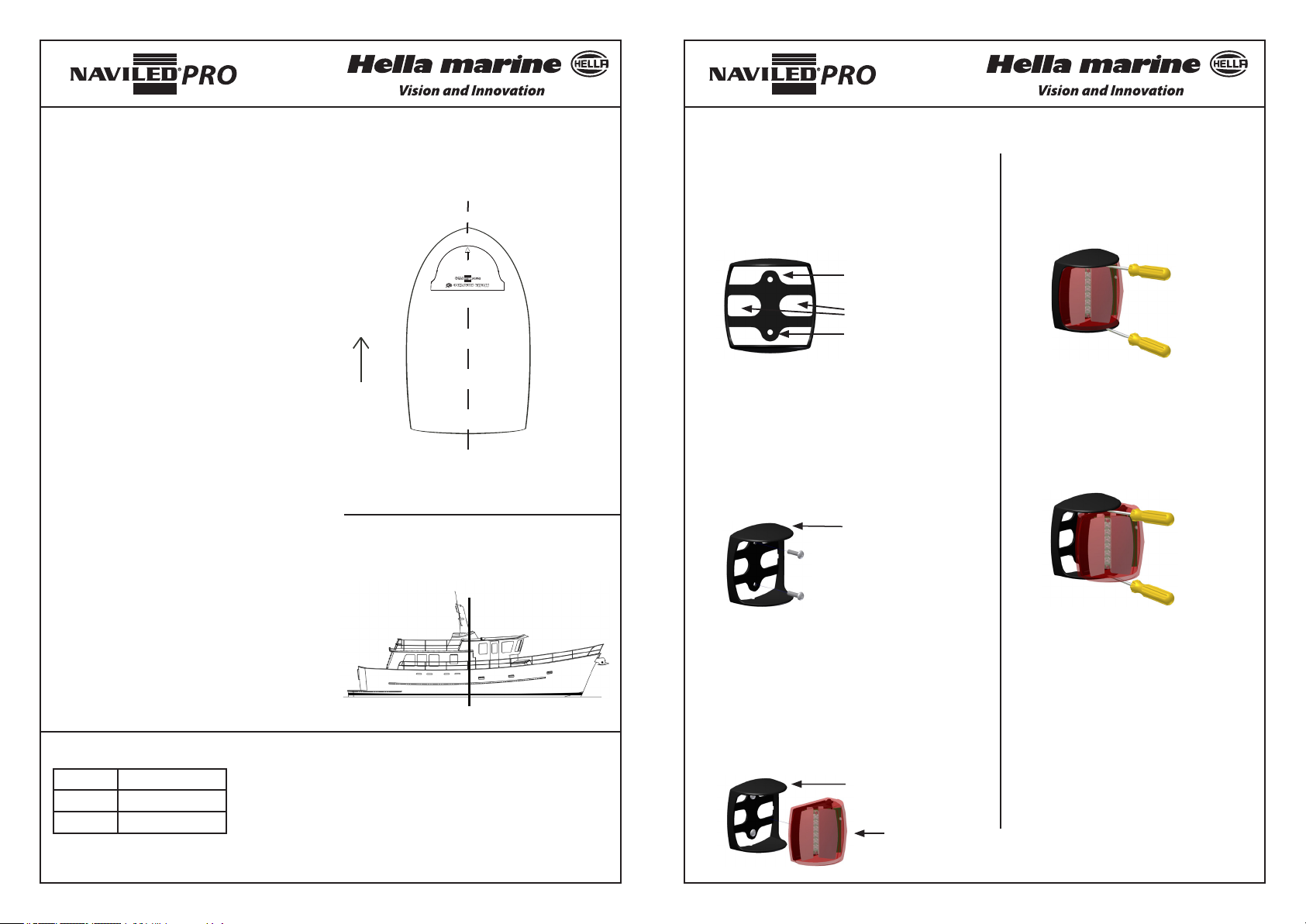
Abb. 1: Im rechten Winkel zur
Mittschisachse
Montage
Schritt 1 – Ausschnitt für Zuleitung vorbereiten
Benutzen Sie die Befestigungslöcher des Gehäuses
als Schablone, um Löcher für die Montage zu
bohren. Lassen Sie genug Platz, um das Kabel
Schritt 1
Vorsichtig 2 Schraubenzieher zwischen
Gehäuse und Optik schieben.
Demontage
durchzuführen.
PositionimVerhältniszurMittschisachse
Die Laterne muss in vertikaler Position und im
rechten Winkel zur Mittschisachse montiert
werden. Der Richtungspfeil auf der Oberseite
2LT 959 940
Made in New Zealand
TOP
Befestigungsloch
des Gehäuses muss nach vorne zeigen (Abb. 1).
Horizontale Ausrichtung
Die Topplaterne sollte generell vor der
Durchführung für Kabel
Befestigungsloch
Querachse angebracht werden (Abb. 2), außer
auf Motorbooten mit einer Länge von weniger
als 20 Metern. Dort muss die Topplaterne nicht
unbedingt vor der Querachse montiert werden,
aber so weit wie möglich vorne, wie dies unter
Berücksichtigung der Anforderungen an die
vertikale Ausrichtung über dem Deck oder den
Seitenlichtern praktikabel ist.
Vertikale Ausrichtung
Die Topplaterne muss auf Schien mit einer
Länge von
Draufsicht
- mehr als 20 Metern: höher als 6 Meter über
dem Deck installiert werden. Die Höhe über
Abb. 2: Horizontale Ausrichtung
Deck muss mindestens so groß sein wie die
maximale Breite des Schis, aber weniger als
Querachse
12 Meter.
- mehr als 12, aber weniger als 20, Metern:
Schritt 2 – Gehäuse befestigen
2.1 Die Beschriftung muss sich auf der
Oberseite des Gehäuses benden.
2.2 Der Richtungspfeil auf der Oberseite des
Gehäuses muss nach vorne zeigen.
2.3 Montieren Sie das Gehäuse mit zwei M5-
Befestigungselementen.
Beschriftung
Verwenden Sie marinetaugliche
Befestigunsgelemente aus
rostfreiem Edelstahl mit einem
breiten, achen Kopf (nicht im
Lieferumfang enthalten)
Schritt 2
Lichtmodul herausziehen.
mindestens 2,5m über dem Deck angebracht
werden.
- weniger als 12 Metern: mindestens 1 Meter
höher als die Seitenlaternen angebracht
werden.
Hinweis: Eventuell abweichende
Ländervorschriften sind zu beachten.
Kabel-Farbkennzeichnung
Farbe verbinden mit
Schwarz Negativ (-)
Rot Signal (+)
Bei Verpolung wird die Laterne nicht beschädigt, aber in ihrer
Funktion beeinträchtigt.
HELLA empehlt, alle Kabelverbindungen zu löten und
anschließend mit Schrumpfschlauch abzudichten.
Schritt 3 – Optik einbauen
Hinweis: Die Signalpfeile auf der Oberseite der
Optik müssen in dieselbe Richtung wie die Pfeile
auf dem Gehäuse zeigen (siehe 2.2).
3.1 Zuleitung nach hinten aus dem Gehäuse führen
3.2 Lichtmodul in Gehäuse einrasten
3.3 Stromanschluss herstellen
Gehäuse
Lichtmodul
Hinw eis: Lichtmodul nicht önen. Es sind
keine wartbaren Teile enthalten.
Hinweis: Die Sicherung der Laterne sollte nicht mehr als 3
Ampere betragen.
www.hellamarine.com
Page 5
Déclaration de garantie
b
a
d
b
a
d
b
d
Félicitations! Le produit que vous venez d'acquérir est conçu et fabriqué par HELL A, l'un
des premiers fabricants mondiaux d'éclairage. Ce produit est couvert par une garantie de 5
ansàpar tirdeladated’achatparl’utilisateurnal,cettegarantiecouvranttoutdéfautliéà
la fabrication, aux matériaux ou aux composants utilisés.
Da n s l' éventu a l i t é pe u pr o bable que vous rencontriez un cas avé r é de ga r a ntie sur le produit acheté ,
HELLA pourra, à sa discrétion, soit réparer, soit remplacer le produit ou encore rembourser celui-ci
à hauteur de sa valeur d’achat.
Pour toute demande de prise en charge d'un produit sous garantie, veuillez retourner celui-ci dans
les délais impartis auprès du revendeur HELLA où l’achat a été eectué.
Cette garantie s’applique en complément et ne s’oppose pas à tous autres droits ou recours dont le
consommateur pourrait bénécier au terme de la législation locale en vigueur relative à la prestation
de biens ou de services.
La garantie ne couvre pas:
1.) les réclamations découlant d’une usure normale du produit ou faisant suite à toute modication ou altération
du produit sous quelque forme que ce soit.
2.) toute réclamation résultant du non-respect des instructions de montage, d’entretien ou d’utilisation ou encore
d’un usage inadapté ou détourné du produit.
3.) tout frais engendrés par la demande de prise en charge.
Pour tout commentaire ou suggestion sur nos produits, nous vous invitons à nous contacter par email : techfeedback@
hellamarine.com
Dégradation des LED causée par les conditions d’utilisation
pendant leur durée de service
L'intensité lumineuse des LED diminue progressivement avec le temps, même si la consommation
d'électricité reste constante. Le taux de déclin de l'intensité lumineuse est lié au courant sortant
qui circule à travers les LED et à leurs températures de fonctionnement. Hella Marine a évalué les
conditions de vie en service des lampes de navigation NavLED® pour assurer la sécurité à long terme
en mer et la conformité aux normes internationales telles que ABYC C-5:2021 & ISO 19009:2015.
Pour continuer à respecter les critères de rendement lumineux énoncés dans sa certication, Hella
Marine suggère de remplacer la lampe NaviLED® PRO 3NM Masthead une fois qu'elle a accumulé
25 000 heures de fonctionnement. Pour déterminer si le seuil de durée de vie a été atteint, vous
aurez besoin d'une estimation annuelle d'utilisation en heures ainsi que de la date de production de
la lampe. La date de production est gravée sur le devant de la lentille dans le format suivant:
JJMMAA_HHMMSS (Jour/Mois/Année_Heure/Minute/Seconde)
Par exemple, si une lampe avec une date de production de 140823_153520 est estimée fonctionner
1500 heures par an, il est concevable que le seuil de durée de vie soit atteint après 16 ans d'utilisation
- approximativement autour de 2039.
Dans le contexte des normes de navigation de plaisance typiques, même avec une navigation de nuit
régulière, il est peu probable que le seuil de durée de vie soit atteint. De plus, il est recommandé
d'eectuer des vérications régulières pendant la durée de vie de la lampe pour s'assurer qu'il n'y a
pas eu de défaillances des LED.
®
NOTICE TECHNIQUE: Feu de hune NaviLED
PRO
d'une portée de 3 milles nautiques
pour: 2LT 959 940-2xx
L e s fe ux de na vi ga t io n à LE D pr o c u re n t de no mb r e ux av an ta g es pa r r a p po r t a u x fe u x co nv e n t io n ne l s
à ampoules tels qu'une consommation électrique extrêmement réduite, une durée de vie étendue
et une résistance élevée aux chocs et aux vibrations. Les feux à LED représentent le choix idéal
pour une utilisation dans un environnement corrosif tel que le milieu marin. Les feux de navigation
NaviLED®PRO de Hella marine sont classés comme des "instruments optiques de précision",
testés et homologués par type selon la réglementation maritime internationale. Ils sont également
couverts par une garantie de 5 ans.
Materiaux Lentille et boîtier haute résistance aux impacts
Portée lumineuse (min) 3 milles nautiques
Taille du navire: Navires de Plaisance < 20m
Cablâge Précâblé avec 2,5m de câble marin à 2 brins
Tension de fonctionnement MultivoltTM 9-33V DC
Consommation électrique < 2.5W (0.2A@ 12V / 0.1A @ 24V)
Niveau de protection IP 67 – Complètement étanche
Poids 250g (câble inclus)
Homologations internationales IMO COL REG 72, ISO 19009:2015, EN 60945:2002
Certication RINA N° ELE118523PU
USCG 33 CFR 183.810, ABYC C-5
ABYC C-5 Testé par: Imanna Laboratory (Date: 1/08/2023)
c
Compatibilité électromagnétique (EMC)
Cet éclairage à LED est un appareil électronique. Les circuits électriques incorporent des composants
qui éliminent les interférences potentielles, tant au niveau des émissions propres à l'appareil qu'à la
susceptibilité aux émissions externes.
Protection contre les dégâts liés aux pics de tension
Ce feu est protégé contre les inversions de polarité jusqu'à -700 volts ainsi que les pics de
tension jusqu'à 500 volts.
a
Dimensions
Dimensions
d
Designé et fabriqué en Nouvelle Zelande
a = 87mm / 3.43”
b
b = 90mm / 3.54”
c = 57mm / 2.25”
d = 50mm / 1.97”
Page 6
Positionnement des feux
Recommendations générales
Lorsque les feux de navigation sont en service,
leur faisceau lumineux ne doit pas être obstrué
ou caché par les superstructures du navire ou
tout autre objet.
Position par rapport à l' axe longitudinal
Le feu de hune doit être positionné
perpendiculairement à l'axe longitudinal du
navire. La èche directionnelle du feu doit pointer
vers l'avant (voir schéma no. 1). Le feu doit être
vertical.
Positionnement horizontal
Le feu de hune doit être positionné en avant de
l'axe transversal du navire sauf sur les unités de
moins de 20 m où le feu de hune ne devra pas
nécéssairement être placé en avant dudit axe
(voir schéma no. 2). Dans ce cas de gure, le feu
sera positionné le plus en avant possible tout en
continuant à prendre en compte les exigences
de placement vertical par rapport au plat-bord ou
aux feux latéraux.
Positionnement vertical
Sur un bateau à moteur de plus de 20 mètres, le
feu de hune doit être placé au minimum 6 mètres
au-dessus du niveau de la coque. La hauteur
devra être supérieure à la largeur de la coque
mais ne devra pas excéder 12 mètres.
Sur un bateau à moteur dont la longueur est
comprise entre 12 et 20 mètres, le feu de hune
doit être placé au minimum 2.5 mètres au-dessus
du plat-bord.
Sur un bateau à moteur dont la longueur est
inférieure à 12 mètres, le feu de hune doit être
placé au minimum 1 mètre au-dessus des feux
latéraux.
Note: il convient également de tenir en compte la
réglementation locale en vigueur.
Codage couleur du câble
Couleur Raccordement
Noir Négatif (-)
Rouge Signal (+)
Les éclairages à LED ont une polarité prédéterminée.
L'inversion de polarité n'endommagera pas ce produit mais ses
fonctions seront rendues inopérantes. HELLA recommande
que les câbles soient soudés et qu'une gaine de protection
thermorétractable soit ajoutée pour garantir l'étanchéité.
NB: Le feu de navigation doit être protégé par un fusible de 3
ampères.
Schéma 1: Perpendiculairement à l'axe
longitudinal du navire
2LT 959 940
Made in New Zealand
TOP
Vue du haut
Schéma 2: Positionnement horizontal
axe transversal
Montage
Etape 1 – Prévoir le passage du câble d’alimentation
Utiliser le boîtier comme gabarit pour marquer les trous
de xation ainsi que le passage du câble.
Trou pour élément de xation
Découpe pour le passage de
câble
Trou pour élément de xation
Etape 2 – Monter le boîtier
2.1 Le boîtier doit être installé avec les repères
Etape 1
Insérer avec précaution 2 tournevis
entre l'ensemble optique et le boîtier.
Etape 2
Dégager le module lumineux.
Démontage
situés sur la surface horizontale supérieure.
2.2 La èche sur le haut du boîtier doit pointer vers
l'avant.
2.3 Utiliser deux éléments de xation de type M5.
Repères
Employer de la visserie
inox de qualité marine
comportant une tête large et
plate (non fourni).
Etape 3 – Insérer l’ensemble optique
A noter – les èches situées sur le haut du boîtier
et du module lumineux doivent pointer dans la même direction.
Note: ne pas ouvrir la lampe, celle-ci
ne contient pas de pièces pouvant être
remplacées.
3.1 Passer le câble d’alimentation à travers le boîtier.
3.2 Pousser l’ensemble optique dans le boîtier
3.3 Brancher le câble d’alimentation
Boîtier
Module lumineux
www.hellamarine.com
 Loading...