


.
BD0053V0004EN0316S0
460 985-69 / 03.16
Operating Instructions
en
CSC-Tool

Inhaltsverzeichnis CSC-Tool
Table of Contents
1 Safety Precautions......................................................................... 3
1.1 General Safety Precautions ...........................................................3
1.2 Safety Precautions for the CSC-Tool..............................................3
1.3 Safety Precautions – Risk of Injury ................................................4
1.4 Safety Precautions – Laser............................................................4
2 Product Description ....................................................................... 5
2.1 Intended Use.................................................................................5
2.2 Delivery Contents..........................................................................5
2.3 Tool Description............................................................................7
3 Working with the CSC-Tool.......................................................14
3.1 Precondition for the Use of the CSC-Tool.....................................14
3.2 Placing the CSC Panel in Front of the Vehicle ..............................14
3.3 Placing the CSC Panel Centred in Front of the Vehicle .................17
3.4 Placing the CSC Panel Parallel to the Vehicle ..............................21
3.5 Adjusting the Height of the Reference Panel ...............................25
4 General Information.....................................................................28
4.1 Care and Maintenance.................................................................28
4.2 Disposal......................................................................................28
4.3 Technical Data for Laser Module .................................................29
2
CSC-Tool Safety Precautions
General Safety Precautions
1 Safety Precautions
1.1 General Safety Precautions
• The CSC-Tool is exclusively intended for use on a vehicle.
It is a precondition for the use of the CSC-Tool that the
user has knowledge of automotive technology and is
therefore aware of the sources of danger and risks in the
repair shop and on motor vehicles.
• All notes given in the individual sections of the operating
instructions apply. In principle it is required to follow the
steps and safety precautions stated below.
• Furthermore, pay attention to all general instructions
from labour inspectorates, trade associations and vehicle
manufacturers as well as all laws, legal ordinances and
instructions which have to be commonly obeyed by a
repair shop.
1.2 Safety Precautions for the CSC-Tool
In order to avoid incorrect handling and injury to the user or
destruction of the CSC-Tool arising from this, pay attention to
the following:
• Only assemble the CSC-Tool according to the assembly
instructions.
• Protect the CSC-Tool from long periods of exposure to
solar radiation.
• Protect the CSC-Tool from water (it is not waterproof).
• Protect the CSC-Tool from strong impacts (do not drop).
• Regularly service the CSC-Tool.
3
Safety Precautions CSC-Tool
Safety Precautions – Risk of Injury
1.3 Safety Precautions – Risk of Injury
When working on the vehicle, there is a risk of injury through
inadvertent rolling of the vehicle. Therefore regard the
following:
• The park position should also be engaged in automatic
vehicles.
• Protect vehicle against rolling away.
1.4 Safety Precautions – Laser
There is a risk of injury through dazzling the eyes when
working with the laser. Therefore regard the following:
• Do not direct the laser beam towards persons, doors or
windows.
• Never look directly into the laser beam.
• Ensure proper room illumination.
• Avoid trip hazards.
• Secure mechanical parts from falling over or becoming
loose.
4
CSC-Tool Product Description
Intended Use
2 Product Description
2.1 Intended Use
The Camera & Sensor Calibration Tool (CSC-Tool) is a system for
calibrating driver assist systems suitable for all makes and models.
Optional modules enable brand-specific adjustments of all kinds of
systems. Therefore, in connection with a diagnostic tool from Hella
Gutmann you are able to calibrate e.g. the front camera for the lane
departure warning system, the radar sensor for the ACC (Adaptive Cruise
Control) or the camera for adaptive headlights.
The CSC-Tool can be exclusively operated in combination with a Hella
Gutmann diagnostic tool. Diagnostic tools from other manufacturers will
not be supported.
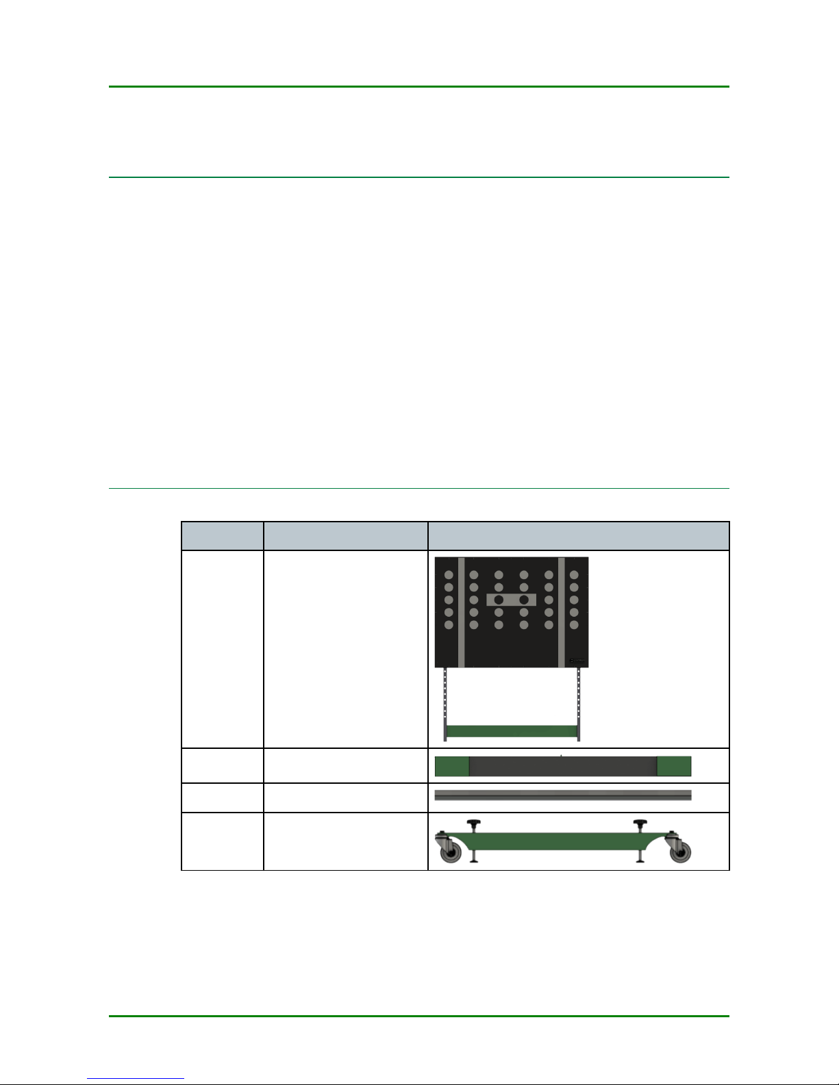
2.2 Delivery Contents
Pieces Designation
1
CSC Panel
1
Cross member
1
Dipstick
2 Base support on
caster wheels
5
Product Description CSC-Tool
Delivery Contents
Pieces Designation
2
HD-10 EasyTouch
incl. wall mount
1
Operating and
installation
instructions
2.2.1 Checking Delivery Contents
Please check the delivery contents upon receiving your tool so that
complaints can be issued immediately regarding potential damage or
missing parts.
Proceed as follows to check the delivery contents:
1. Check the package delivered to ensure that it is not damaged.
Should you identify any damage to the package, then open the package
in the presence of the delivery service and check the CSC-Tool for
hidden damage. Any transport damage to the package supplied and
damage to the CSC-Tool shall be registered in a damage report by the
delivery service.
2. Open the package supplied and check for completeness based on the
delivery slip.
CAUTION
Risk of injury due to heavy tool
The tool may drop down and cause injuries during
unloading.
Always unload the tool with the aid of a second person.
Use suitable aids as necessary.
6

CSC-Tool Product Description
Tool Description
3. Remove the CSC-Tool from the packaging.
4. Check the CSC-Tool for damage and completeness.
2.3 Tool Description
2.3.1 CSC Panel
7

Product Description CSC-Tool
Tool Description
8

CSC-Tool Product Description
Tool Description
Designation
1
Reference panel
Here you will need different reference panels depending on
the car manufacturer. These are optionally available.
2
Mirror cover/scale of cross member
Here you can check whether the CSC Panel is placed centred
in front of the vehicle.
3
Mirror of cross member
This is used to reflect the laser beam onto the scale of the
HD-10 EasyTouch.
4
Cross member
5
Adjustment screws of the base support
Use the adjustment screws to balance the level gauge of the
base support.
6
Level gauge
Use the level gauge to check whether the base support is
exactly horizontal.
7
Set screw on reference panel
Use the set screw to fix the reference panel at the
appropriate height.
8
Handle
Use this handle to move the reference panel upwards or
downwards.
9
Dipstick with set screw
Here you can read the height of the reference panel.
10
Color marking
Here you can check the nominal height of the reference panel
indicated in the diagnostic tool.
9

Product Description CSC-Tool
Tool Description
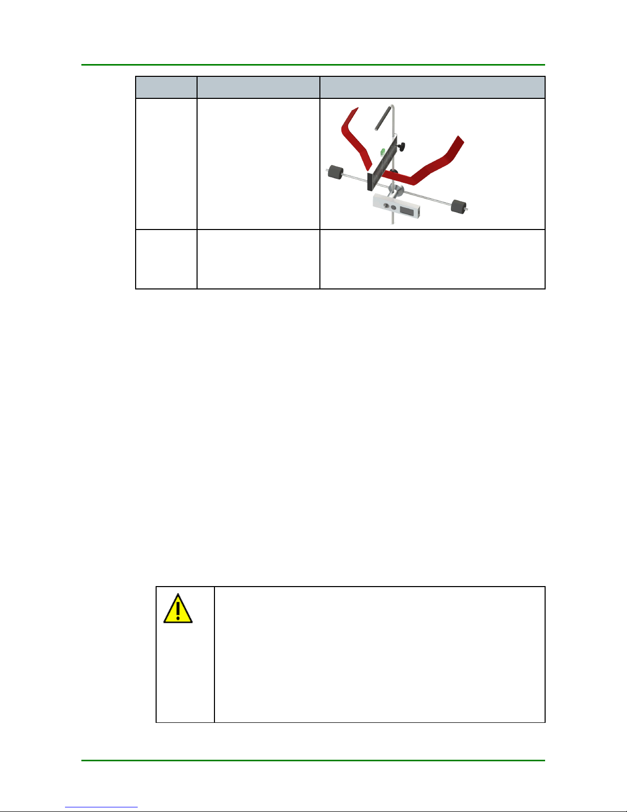
2.3.2 HD-10 EasyTouch
Designation
1
Handle
This handle makes it easier to carry the HD-10 EasyTouch.
2
Scale of the HD-10 EasyTouch
Here you can check whether the CSC Panel is placed parallel
to the vehicle.
10

CSC-Tool Product Description
Tool Description
Designation
3
Set screw on scale
Use this set screw to adjust and fix the scale.
4
Attachment bracket for automobile
Use this attachment bracket to attach the HD-10 EasyTouch
to the tyre.
5
Shaft with cross connector
6
Set screw on shaft with cross connector
Use this set screw to adjust the height of the shaft with cross
connector.
7
Laser module
The actual value can be projected onto the scale of the cross
member of the CSC Panel with the help of the laser.
8
Protective cylinder set
This protects the wheel rim from damage.
9
Level gauge
Use the level gauge to check whether the HD-10 EasyTouch
is placed horizontally.
2.3.3 Laser Module
11

Product Description CSC-Tool
Tool Description
Designation
1
Output of the laser beam/laser beam
Output for laser beam.
Use the laser beam to read the actual value at the scales of
the cross member and at the HD-10 EasyTouch.
2
Mounting bolt
Use this to adjust and secure the laser module.
3
Switch
Switch the laser on and off.
4 Battery compartment cover
2 type AA batteries can be inserted into the battery
compartment.
2.3.4 Replacing the Batteries
Replacing the Type AA Batteries
Proceed as follows to replace the batteries:
1. Switch off the laser beam (1) with the switch (3).
2. Remove the battery compartment cover (4), tilting it from the bottom
side towards the top.
12

CSC-Tool Product Description
Tool Description
3. Remove the batteries individually.
NOTE
Pay attention to correct installation direction/polarity
4. Reassembly in reverse order
13

Working with the CSC-Tool CSC-Tool
Precondition for the Use of the CSC-Tool
3 Working with the CSC-Tool
The following steps are necessary to work with the CSC-Tool:
1. Place the CSC Panel in front of the vehicle.
2. Place the CSC Panel centred in front of the vehicle.
3. Place the CSC Panel parallel to the vehicle.
4. Adjust the height of the reference panel.
The individual steps are described below.
3.1 Precondition for the Use of the CSC-Tool
Regard the following in order to use the CSC-Tool:
• Vehicle system is working properly.
• No trouble codes stored in ECU memories.
• Possible vehicle-specific preparations done.
• Rear axle track properly adjusted.
3.2 Placing the CSC Panel in Front of the Vehicle
Proceed as follows to place the CSC Panel in front of the vehicle:
1. Connect the diagnostic tool to the vehicle (see user manual).
2. Select >Diagnostics< in the main menu.
3. Select the system to be calibrated, e.g. front camera or ACC under
>Basic setting<.
A window with information and instructions appears.
14
CSC-Tool Working with the CSC-Tool
Placing the CSC Panel in Front of the Vehicle
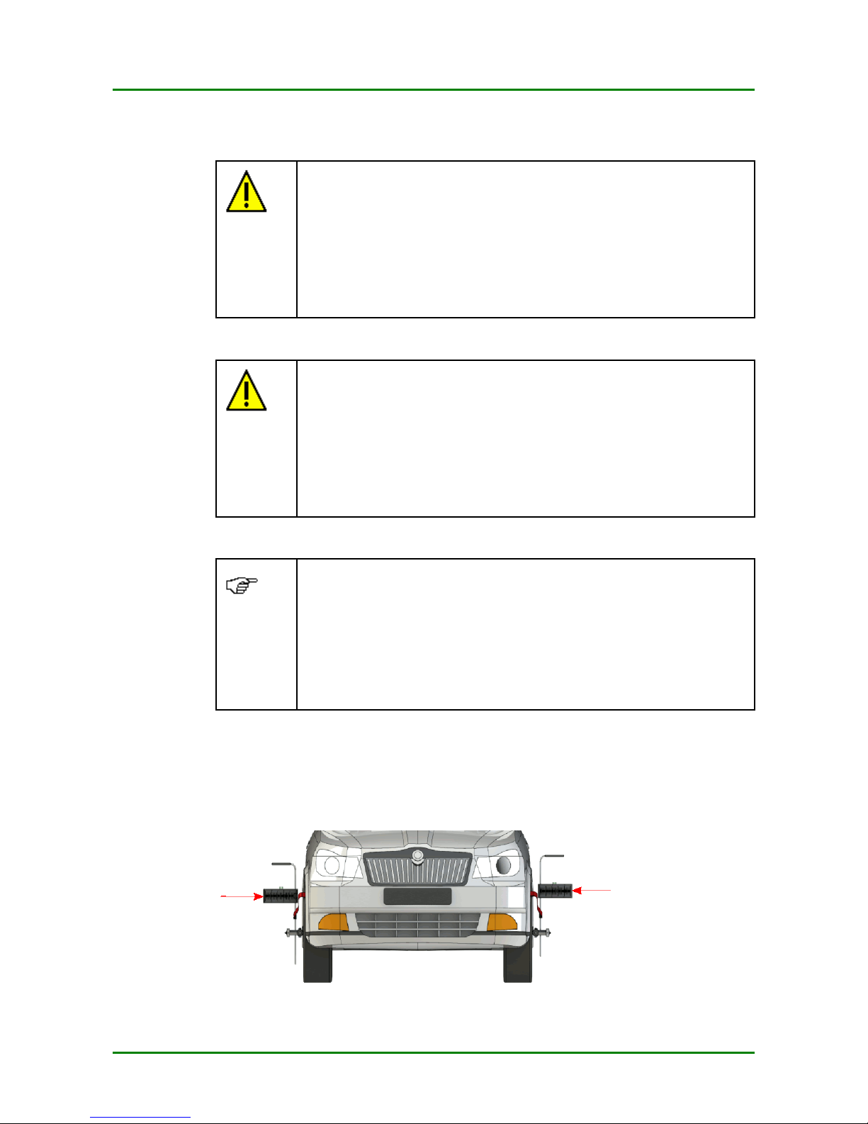
4. Regard the window with information and instructions.
WARNING
Sharp object
Risk of injury/piercing
Using the handle, always attach the HD-10 EasyTouch to
the rim flange or tyre.
CAUTION
Scratching of surfaces
Damage to wheel rims
Always attach the protective cylinder set to the rim flange
or tyre.
NOTE
The distance between the CSC Panel and the centre of the
wheel can be measured with a yard stick (not included in
the delivery contents) only if the HD-10 EasyTouch is
attached horizontally and centred to the centre of the
wheel.
5. Install one HD-10 EasyTouch on the left and right front wheel
respectively.
15

Working with the CSC-Tool CSC-Tool
Placing the CSC Panel in Front of the Vehicle
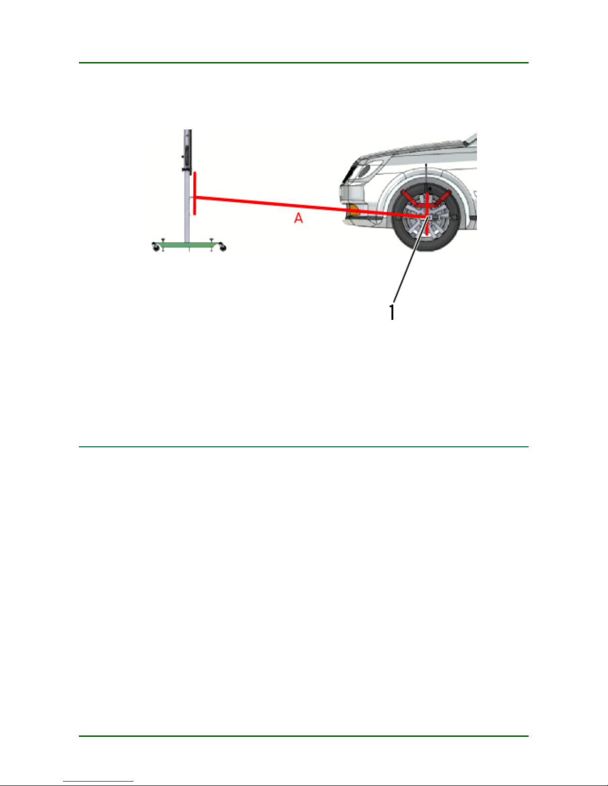
6. On the HD-10 EasyTouch, loosen the set screw of the shaft with cross
connector (6).
Now you can adjust the height of the shaft with cross connector.
7. Align the shaft with cross connector (5) to the wheel centre 1.
8. Align the scales of the HD-10 EasyTouch at a right angle.
9. Use a yard stick (not included in the delivery contents) to measure
from the centre of the wheel 1 to the rear edge (see marking) of the
cross member (4).
16
CSC-Tool Working with the CSC-Tool
Placing the CSC Panel Centred in Front of the Vehicle
10. Place the CSC Panel with the distance A, indicated in the diagnostic
tool, to the centre of the wheel 1.
11. Perform steps 6 to 10 for the second HD-10 EasyTouch.
Now the CSC Panel is placed correctly in front of the vehicle.
3.3 Placing the CSC Panel Centred in Front of the Vehicle
Proceed as follows to place the CSC Panel centred in front of the vehicle:
17
Working with the CSC-Tool CSC-Tool
Placing the CSC Panel Centred in Front of the Vehicle
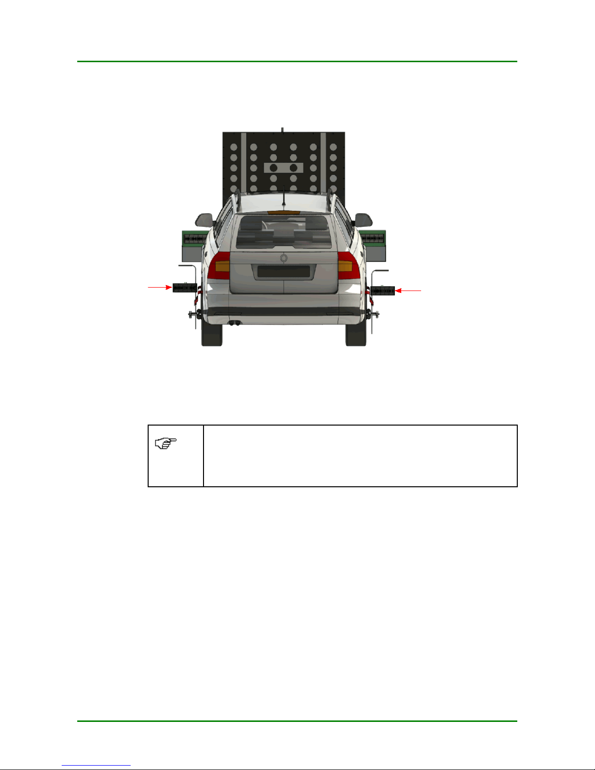
1. Attach one HD-10 EasyTouch on the left and right rear wheel
respectively.
2. Align the scales of the HD-10 EasyTouch at a right angle.
NOTE!
Ensure that the level bubbles of both HD-10 EasyTouch
devices are centred.
18

CSC-Tool Working with the CSC-Tool
Placing the CSC Panel Centred in Front of the Vehicle
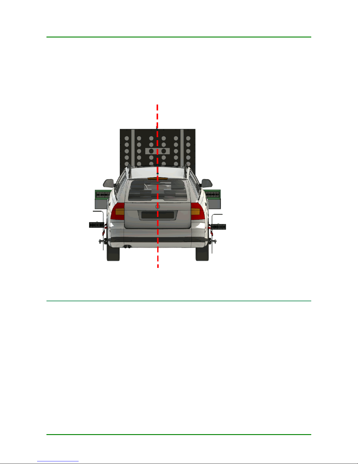
3. The left and right mirror covers (2) of the cross member (4) should be
tilted upwards.
The scales of the cross member and mirrors are visible.
CAUTION
Laser radiation
Damage to/destruction of the retina
Never look directly into the laser beam.
4. Switch on the laser beam (1) of the laser module (7) with the switch
(3).
19

Working with the CSC-Tool CSC-Tool
Placing the CSC Panel Centred in Front of the Vehicle
5. Align the laser module (7) by turning the mounting bolt (2) on the scale
of the cross member (4).
The laser beam is indicated on the scale of the cross member.
20
CSC-Tool Working with the CSC-Tool
Placing the CSC Panel Parallel to the Vehicle
6. Perform steps 4 + 5 for the second laser module.
7. By moving the CSC Panel laterally, place the panel in a way that the
left and right scale of the cross member (4) show the same values.
Now the CSC Panel is placed centred in front of the vehicle.
3.4 Placing the CSC Panel Parallel to the Vehicle
Proceed as follows to place the CSC Panel parallel to the vehicle:
21

Working with the CSC-Tool CSC-Tool
Placing the CSC Panel Parallel to the Vehicle
1. Align the laser beam (1) of the laser module (7) with the mirror (3) of
the cross member (4).
The laser beam will be reflected from the mirror to the scale of the
HD-10 EasyTouch.
2. Perform step 1 with the second laser beam.
22

CSC-Tool Working with the CSC-Tool
Placing the CSC Panel Parallel to the Vehicle
3. By axially turning the CSC Panel, place the panel in a way that the left
and right scale of the HD-10 EasyTouch show the same values.
Now the CSC Panel is placed parallel to the vehicle.
23

Working with the CSC-Tool CSC-Tool
Placing the CSC Panel Parallel to the Vehicle
4. Switch off the laser beam (1) of the laser module (7) with the switch
(3).
5. Use the adjusting screws of the base support (5) to adjust the
horizontal and the vertical level gauge (6) of the cross member (4) and
CSC Panel accordingly.
The adjusting screws also prevent the CSC panel from slipping. The
CSC panel is held in place and can no longer be moved.
If the horizontal and vertical level gauges are centred and even, you
can adjust the height of the reference panel.
24

CSC-Tool Working with the CSC-Tool
Adjusting the Height of the Reference Panel
3.5 Adjusting the Height of the Reference Panel
Proceed as follows to adjust the height of the reference panel:
WARNING
Movable reference panel
Risk of injury or pinching
Use only the handle to move the reference panel.
1. Loosen the left and right set screws (7) on the back of the reference
panel (1).
2. Position the dipstick (9) on the floor.
Now you can adjust the height of the reference panel.
25

Working with the CSC-Tool CSC-Tool
Adjusting the Height of the Reference Panel
3. Use the handle (8) to move the reference panel (1) up to the height
indicated in the diagnostic tool.
4. Check the height of the reference panel (1) using the color marking
(10).
5. Tighten the left and right set screws (7).
26

CSC-Tool Working with the CSC-Tool
Adjusting the Height of the Reference Panel
6. Slightly push the dipstick (9) upwards from the floor and fix it with the
set screw of the measuring rod (9). Then it cannot be damaged when
moving the CSC Panel again.
7. Start the calibration in the diagnostic tool with
.
27

General Information CSC-Tool
Care and Maintenance
4 General Information
4.1 Care and Maintenance
• As with every tool, the CSC-Tool should also be handled with care.
• Regularly lubricate moving parts with acid-free and resin-free grease
or oil.
• Re-tighten the mounting bolts regularly.
• Regularly clean the CSC-Tool with non-aggressive cleaning agents.
• Use commercial household cleaning detergents and a moistened, soft
cleaning cloth.
• Replace damaged accessories immediately.
• Always use original spare parts.
4.2 Disposal
In compliance with directive 2002/96/EC of the European Parliament and
Council of 27 January 2003, relating to used electrical and electronic
appliances, and the national statute governing the distribution, return and
environmental disposal of electrical and electronic appliances (Waste
Electrical and electronic Equipment (WEEE) regulation) of 16 March 2005,
we are obliged to take back this device, distributed after 13 August 2005,
at the conclusion of its service life and to dispose it in accordance with the
above mentioned directives.
Since, in the case of the present device, this relates to exclusively
commercially used equipment (B2B), it must not be handed over to a
public disposal facility.
The device can be disposed of at the following address (specifying the date
of purchase and the device number):
Hella Gutmann Solutions GmbH
Am Krebsbach 2
79241 Ihringen
GERMANY
WEEE reg. no. DE 25419042
Phone: +49 7668 9900-0
28

CSC-Tool General Information
Technical Data for Laser Module
Fax: +49 7668 9900-3999
Mail: info@hella-gutmann.com
4.3 Technical Data for Laser Module
General data
Ambient temperature Recommended: 0 - 35°C
Operating range: 0 - 50°C
Supply voltage
2.7 - 3.3 V DC
Batteries 2x 1.5 V AA
Laser
Wavelength
635 nm
Output 1 mW
Class
2
Operating range 0 - 10 m
29

Notes
CSC-Tool
Notes
30

CSC-Tool
Notes
Notes
31

HELLA GUTMANN SOLUTIONS GMBH
Am Krebsbach 2
79241 Ihringen
GERMANY
Phone: +49 7668 9900–0
Fax: +49 7668 9900–3999
info@hella-gutmann.com
www.hella-gutmann.com
© 2016 HELLA GUTMANN SOLUTIONS GMBH
1 STUECK/PIECE(S)
*9XQ 460 985-691*
9XQ 460 985-691
Made in Germany
 Loading...