

Hella TC-400 Installation Instructions Manual
Montageanleitung
Reifendruckkontrollsystem
Installation Instructions
Tire Pressure Monitoring System
Monteringsanvisning
Däcktrycksövervakningssystem
Montagehandleiding
Bandenspanningscontrolesysteem
Asennusohje
Paineenvalvontajärjestelmä
TC-400
Instructions de montage
Système de contrôle de pressiondes pneumatiques
Instrucciones de montaje
Sistema de regulación de la
presión de los neumáticos
Instruzioni di montaggio
Sistema di controllo pressione
pneumatici
22
DDEEUUTTSSCCHH
Technische Änderungen vorbehalten
EENNGGLLIISSHH
Subject to alteration without notice
FFRRAANNÇÇAAIISS
Sous réserve de modifications techniques
SSVVEENNSSKKAA
Med föfbehåll för tekniska förändringar
NNEEDDEERRLLAANNDDSS
Technische wijzigingen voorbehouden
EESSPPAAÑÑOOLL
Reservadas modificaciones técnicas
IITTAALLIIAANNOO
Con riserva di modifiche tecniche
SSUUOOMMII
Oikeus teknisiin muutoksiin pidätetään
D
GB
F
S
NL
E
I
FIN

Vorsichtsmaßnahmen
Das Reifendruckkontrollsystem nur von Fachleuten einbauen lassen.
Funkcode und alle Systeme in einem tragbaren Speichermedium festhalten.
Vor dem Ausführen von Arbeiten an der Elektroanlage des Autos die negative
Batterieklemme lösen.
Zum Schutz des Kabelsatzes und der Antenne vor Beschädigung darauf achten, dass
Kontakt mit scharfen Kanten vermieden wird.
Darauf achten, dass Kabelsatz und Antenne in der richtigen Position verlegt und befestigt
werden.
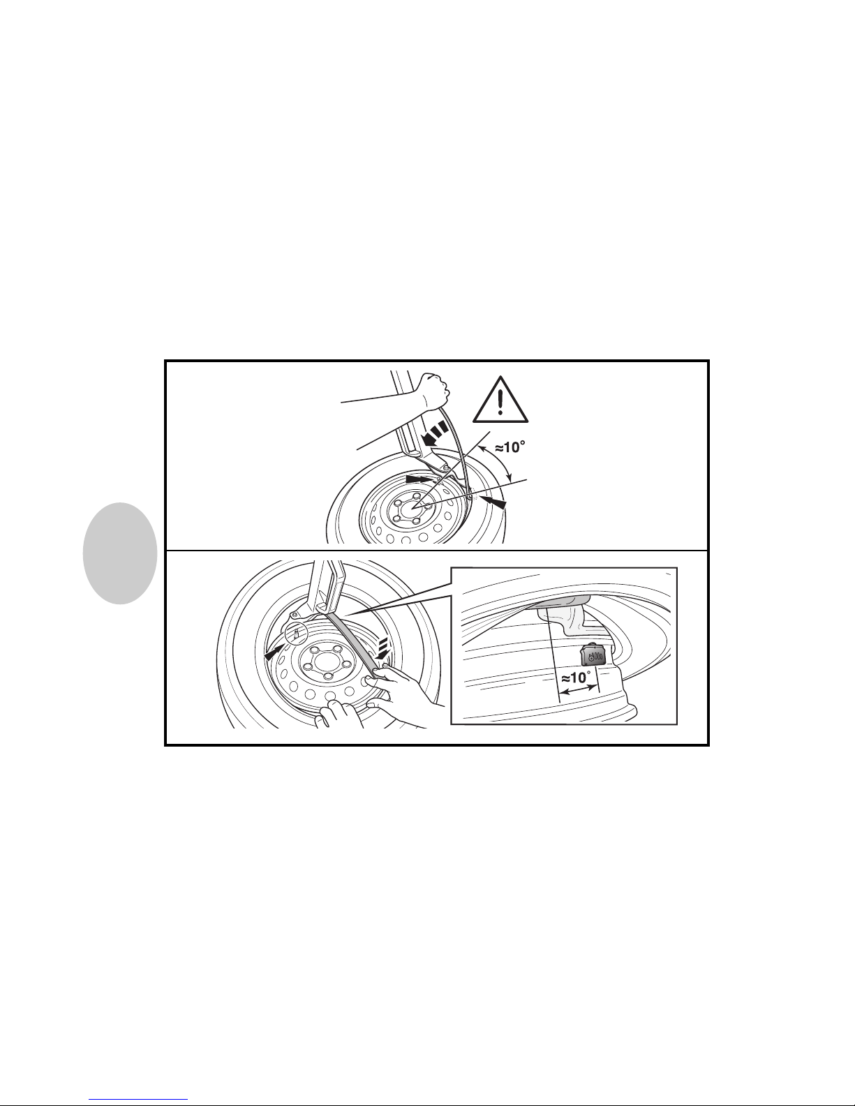
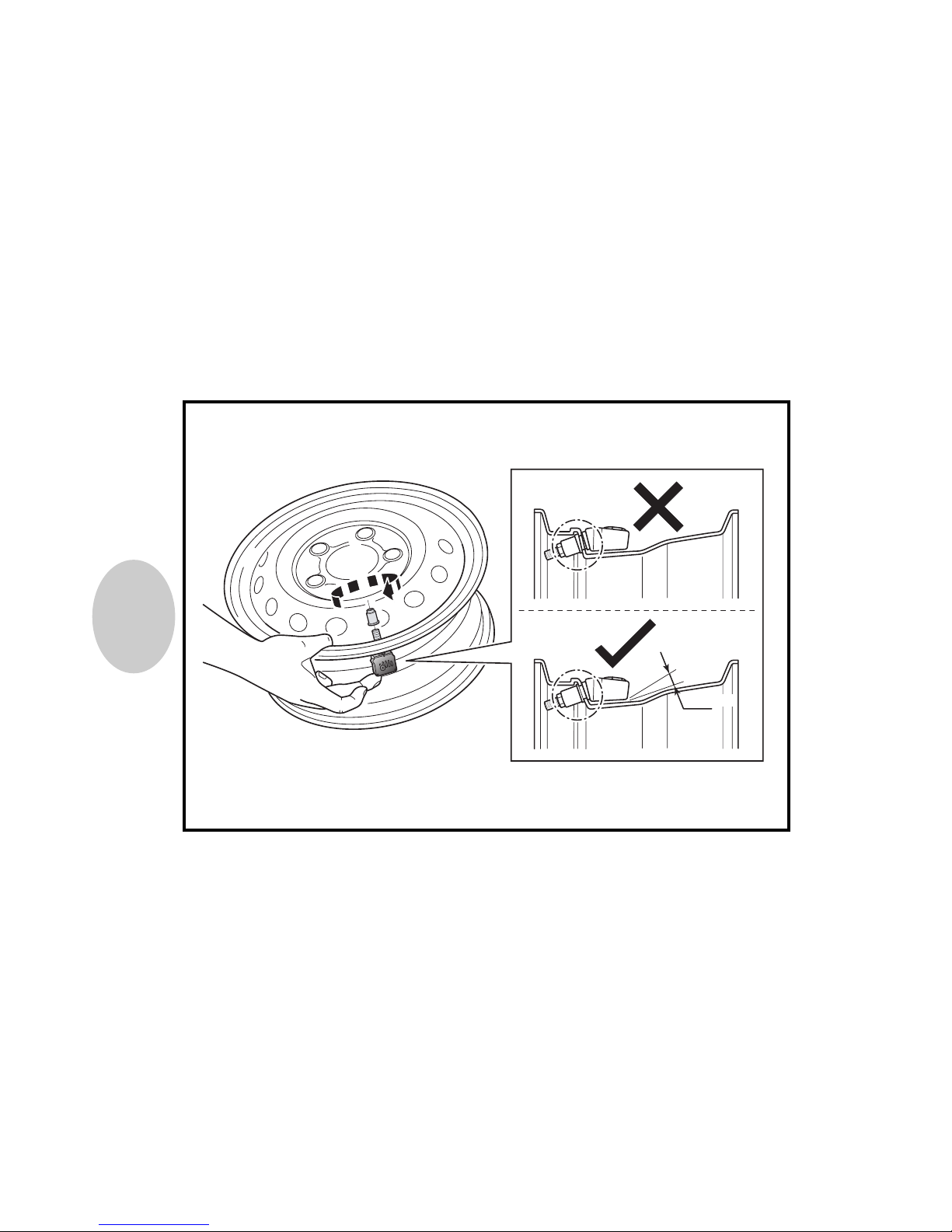
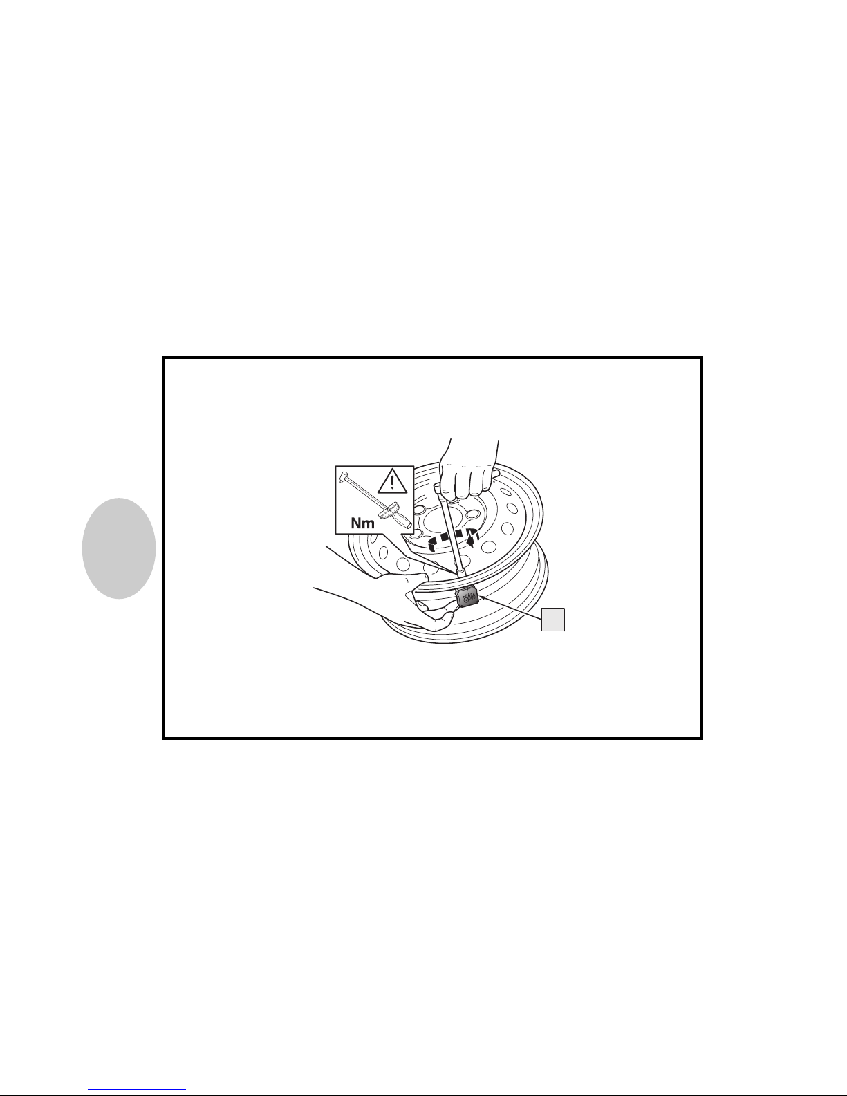
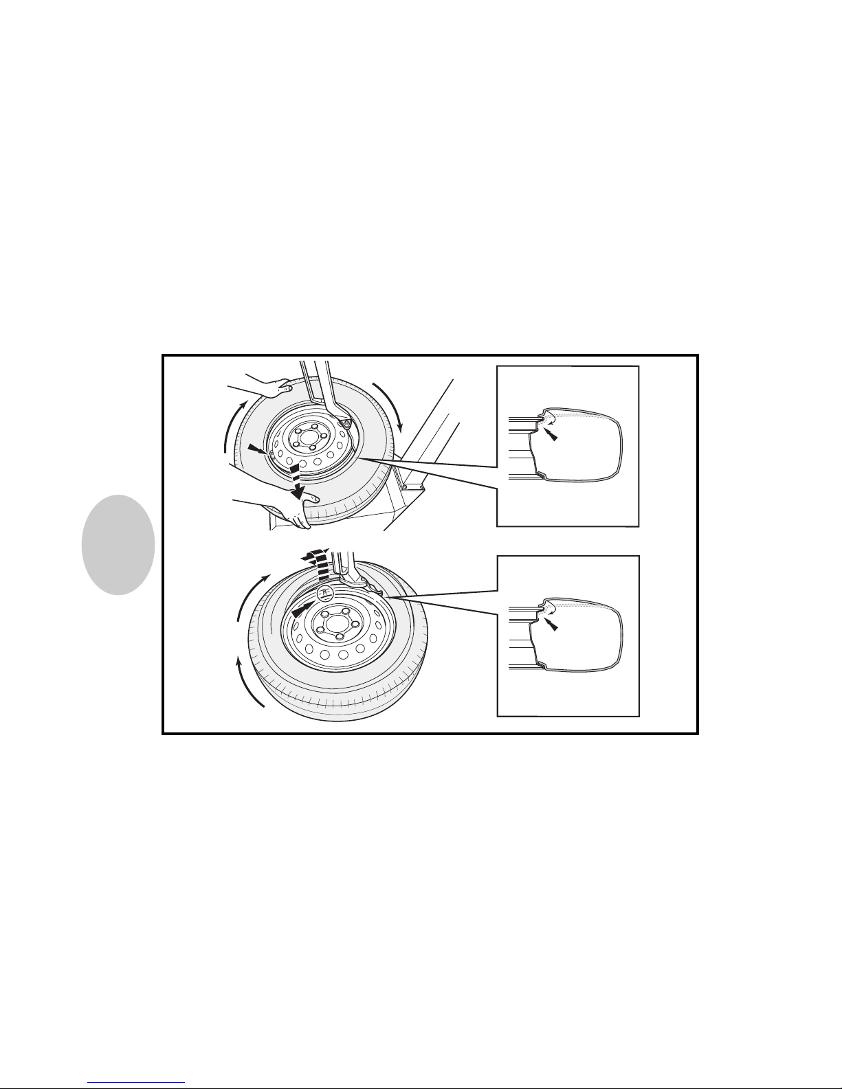
Alle Teile wie in den Abbildungen dargestellt einbauen.
Demontage und Montage von Fahrzeugteilen zur Verlegung von Kabelsatz und Antenne:
siehe Werkstattanleitung für das Auto.
D
Precautions
The Tire Pressure Monitoring System needs to be professioanlly installed.
Note radio code and all systems with a versatile memory.
Disconnect the negative battery terminal before working on the electrical system of the car.
To avoid damage to the wire harness / antenna, ensure contact with sharp edges is
prevented.
Ensure that the wiring harness / antenna are routed and fixed in the correct position.
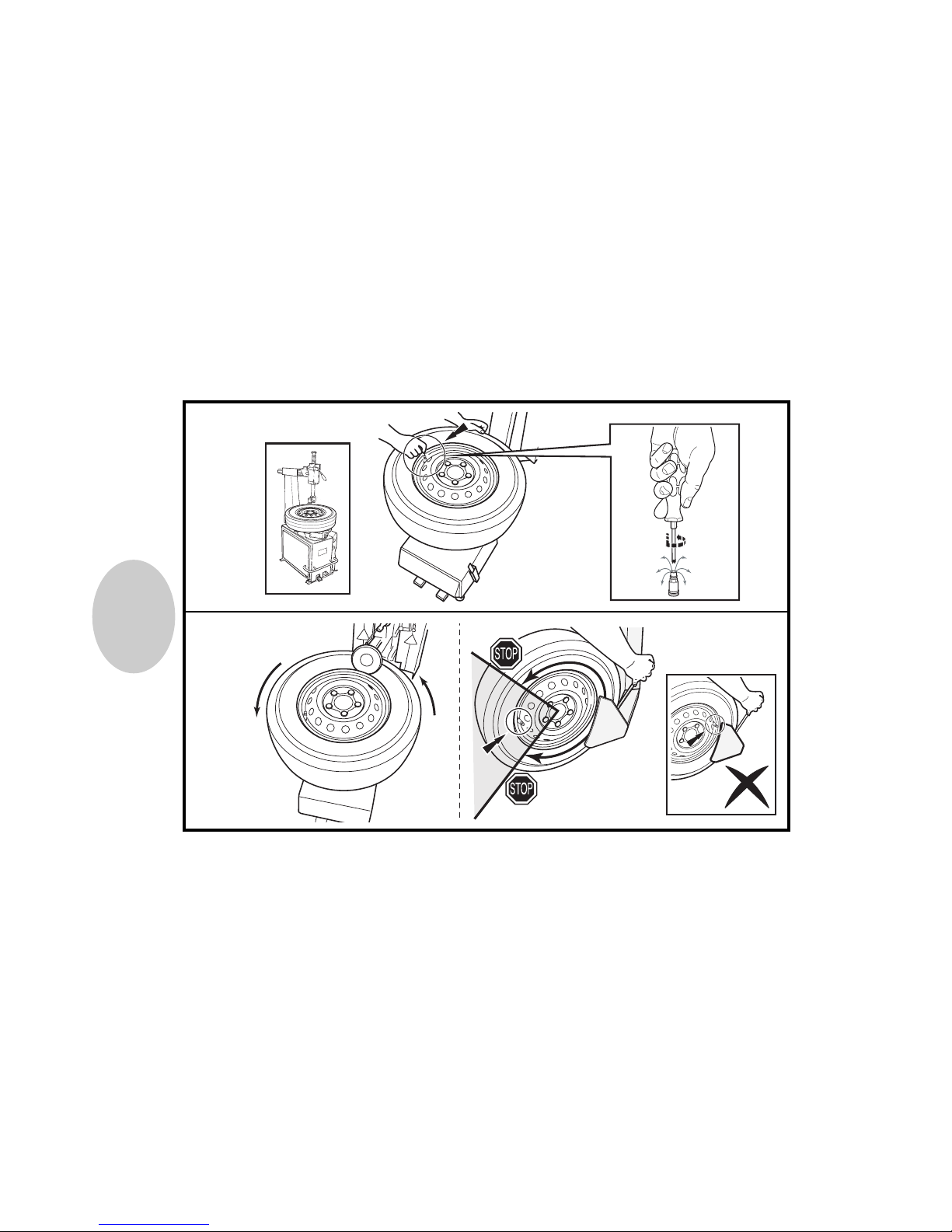
Install all parts as shown in illustrations.
Disassembly / assembly of vehicle parts to route wiring harness / antennas: see vehicle
workshop manual.
GB
33
77
A
D
E
I
M
H
F
J
B
L
K
N
G
C
LLiieeffeerruummffaanngg
4x
3x
25x

88
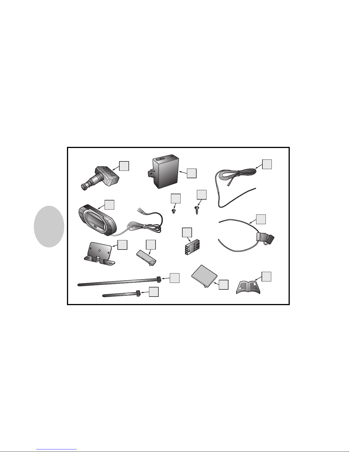
Radsensoren 4 Stück (A), Receiver (B), flexible Antenne (C), LCD-Display (D), Schraube 5 x 3 mm
(E), Schraube 12 x 4 mm (F), Stromkabel mit Sicherung (G), Halterung für das Display (H), doppelseitiges Tapepad 45 x 19 mm (I), 4-Pin-Stecker (J), Kabelbinder 4,8 x 432 mm (K), Kabelbinder 4,8
x 432 mm (L), doppelseitiges Tapepad 45 x 19 mm (M), Montage- und Bedienungsanleitung (N).
GB
4 capteurs de roue (A), module récepteur (B), antenne flexible (C), écran LCD (D), 5 vis 3mm (E),
12 vis 4mm (F), faisceau électrique avec fusible (G), support de montage écran (H), bride double
face 45x19mm (I), connecteur 4 voies (J), attache-câble 4,8x 432mm (K), attache-câble 4,8x
432mm (L), bride double face 45x19mm (M), manuel d'utilisation et de montage (N),
F
Sensores de ruedas 4x(A), módulo receptor (B), antena flexible (C), pantalla LCD (D), tornillo 5x3
mm (E), tornillo 12x4 mm (F), mazo de cables eléctricos con fusible (G), soporte para pantalla (H),
cinta adhesiva de doble cara 45x19 mm (I), conector de 4 clavijas (J), sujetacables 4,8x432 mm
(K), sujetacables 4,5x432 (L), cinta adhesiva de doble cara 45x19 mm (M), manual de instalación
y de usuario (N)
S
D
LLiieeffeerruummffaanngg
VVoolluummeenn ddee ssuummiinniissttrroo
CCoonntteennuu dduu kkiitt
KKiitt CCoonntteenntt
Wheel sensors 4x(A), Reciever module(B), Flexible antenna(C), LCD Display(D), Screw 5x3mm(E),
Screw 12x4mm(F), Power harness with fuse(G), Display mounting bracket(H), Double sided tape
pad 45x19mm(I), Connector 4-pin(J), Cable tie 4,8x 432mm(K), Cable tie 4,8x 432mm(L),
Double sided tape pad 45x19mm(M), Installation and user manual(N),
1111
b
a
01
02
1122
03
04
0-3 mm
1133
05
1144
5
A
06

1155
A10-560012A 086000202 LF
For use in all EU member states
LF = LEFT FRONT
A10-560012A 086000202 RF
For use in all EU member states
RF = RIGHT FRONT
A10-560012A 086000202 LR
For use in all EU member states
LR = LEFT REAR
A10-560012A 086000202 RR
For use in all EU member states
RR = RIGHT REAR
07

1166
08
1177
09

1188
v 160km/h
2S5A-1532-AA
Bar/psi/kPa
155/70R13 2,3/33/230 2,5/36/250 1,8/26/180 2,5/36/250
165/65R13 2,1/30/210 2,5/36/250 1,8/26/180 2,5/36/250
165/60R14 2,3/33/230 2,5/36/250 1,8/26/180 2,5/36/250
1-3 1-3 4
4
10
 Loading...