

Hella 4724 Operation And Installation Instructions Manual

100
68
75
54.8
All dimensions in mm
Specifications:
Continuous rating: 275 amps DC
Intermittent rating: 455 amps DC
Cranking rating: 1250 amps DC
Maximum Voltage: 32 volts DC
Operation: Manual Manual On/Off
Auto Motorised On/Off
Mounting: Recessed or surface
Auto Operating range: 8 to 30 volts DC
Stud Size: 2 x 10mm (3/8”)
Power draw: Switch in off position: 15mA
Max. Cable Size: 50mm
2
53
Part No: 4724
MOTORISED BATTERY SWITCH
Operation and Installation Instructions
IMPORTANT
It is the installer’s responsibility to fit and use this product in a manner that will not
cause accidents, personal injury or property damage. Please follow the installation
instructions supplied. If installation is not correct, the unit may not perform at its
designed potential.
Manufactured for Hella by BEP Marine Limited
959 150-62 V00
Features
• Ignition protected
• Tin plated copper studs and nuts
HELLA - New Zealand Limited
81-83 Ben Lomond Crescent
Pakuranga, Auckland, New Zealand
PO Box 51427, Auckland 2140
Introduction:
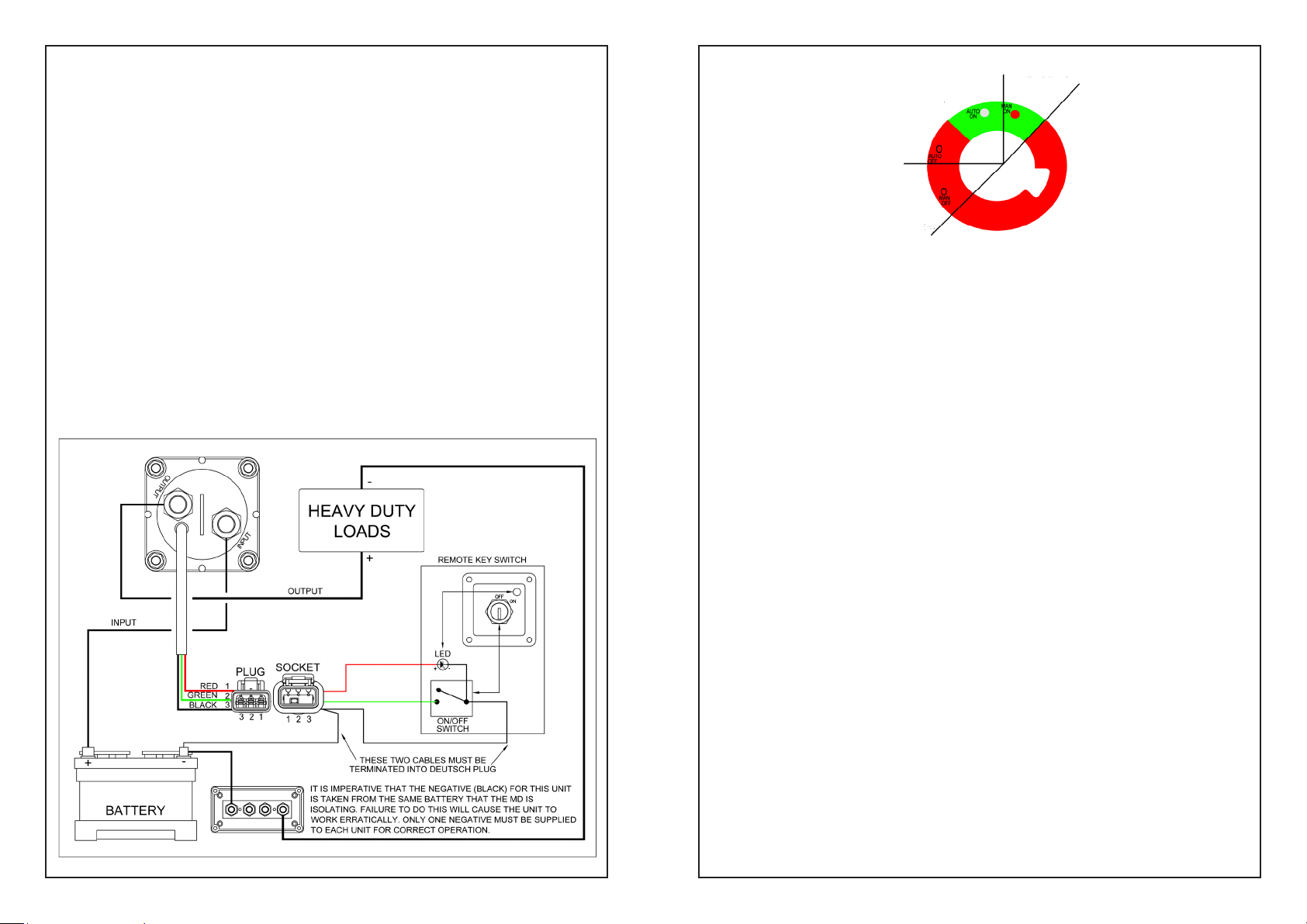
Manual on
The Motorised Battery Switch has the same mechanism as the well proven part number
4640. The essential difference being the switching action has been motorised.
This permits switching of battery banks remotely. A typical installation is a key operated
switch at the helm station and the motorised battery switch installed as close as practical to
the battery bank.
Apart from the convenience of such an installation, this arrangement permits much shorter
cable runs to starter motors and other high current applications such as bow thrusters and
inverters. As a result voltage drop and use of heavy cable can be kept to a minimum.
General Operation:
The Motorised Battery Switch has two modes of operation, auto and manual. There is a LED
located on the battery switch indicating battery switch status.
Auto On & Off
Manual off
Fig 1
Auto Operation:
The 4724 moves from a state of “Auto Off” to “Auto On” when the remotely
mounted switch is turned on. During the time that the battery switch is in “Auto
On” mode, the “Auto On” LED is illuminated.
Auto operation of the Battery Switch is not possible whilst in manual mode. If auto
operation is attempted, the LED will flash
for 3 seconds then stop. Knob must be returned to “Auto Off” before normal auto
operation can continue.
Auto Mode LED Indications:
LED OFF: Battery switch is off
LED ON: Battery switch is on
LED FLASHING: LED flashes whilst moving between auto on and
auto off.
LED Rapid Flash: On 0.1 sec & Off 0.1 Sec:
Voltage is outside specification i.e. Less than 8
volts or greater than 30 volts.
Manual Operation:
The automatic operation of the battery switch can be overridden at anytime by
depressing the control knob and turning clockwise towards the “Man On” position
or counter clockwise towards the “Man Off” position. During the time that the
Battery switch is in “Man On” mode, the “Man On” LED is
Illuminated.
Refer to Fig 1.
Manual Mode LED Indications:
LED OFF: Battery Switch is off
LED ON: Battery Switch is on
 Loading...