

Page 1

BEDIENUNGSANLEITUNG
INSTRUCTION MANUAL
deutsch/english
GERMANY
1000
SPL High Power Amplifier
Page 2
Sehr geehrter Kunde,
wir gratulieren Ihnen zum Kauf dieser hochwertigen HELIX
SPXL-Endstufe. Dieser Verstärker wurde nach neuesten
DEUTSCH
technischen Erkenntnissen entwickelt und zeichnet sich
durch hervorragende Verarbeitung und überzeugende
Technologie aus. Nach mehr als 27 Jahren Erfahrung in der
Forschung und Entwicklung von Audiokomponenten setzt
er neue Maßstäbe in puncto Preis-Leistungsverhältnis der
SPL-Klasse. Das puristisch-hochwertige HELIX SPXL-Design
macht ihn zu einem außergewöhnlichen, leistungsstarken
SPL-Verstärker der Spitzenklasse. Viel Freude an diesem
Produkt wünscht Ihnen das Team von
AUDIOTEC FISCHER
Allgemeines zum Einbau von HELIX-Verstärkern
Um alle Möglichkeiten optimal ausschöpfen zu können, lesen Sie
bitte sorgfältig die nachfolgenden Installationshinweise. Wir
garantieren, dass jedes Gerät vor Versand auf seinen einwandfreien Zustand überprüft wurde.
Vor Beginn der Installation unterbrechen Sie den Minusanschluss
der Autobatterie. Wir empfehlen Ihnen, die Installation von einem
Einbauspezialisten vornehmen zu lassen, da der Nachweis eines
fachgerechten Einbaus und Anschlusses des Gerätes
Voraussetzung für die Garantieleistungen sind.
Installieren Sie Ihren Verstärker an einer trockenen Stelle im Auto
und vergewissern Sie sich, dass der Verstärker am Montageort
genügend Kühlung erhält. Montieren Sie das Gerät nicht in zu kleine, abgeschlossene Gehäuse ohne Luftzirkulation oder in der
Nähe von wärmeabstrahlenden Teilen oder elektronischen
Steuerungen des Fahrzeuges.
Im Sinne der Unfallsicherheit muß der Verstärker professionell
befestigt werden. Dieses geschieht über die 4 beiliegenden
Schrauben, die in eine Montagefläche eingeschraubt werden, die
genügend Halt bieten muss. Bevor Sie die Schrauben im
Montagefeld befestigen, vergewissern Sie sich, daß keine elektrischen Kabel und Komponenten, hydraulische Bremsleitungen, der
Benzintank etc. dahinter verborgen sind. Diese könnten sonst
beschädigt werden. Achten Sie darauf, dass solche Teile sich auch
in der doppelten Wandverkleidung verbergen können.
Allgemeines zum Anschluss der Verstärker
Der Verstärker darf nur in Kraftfahrzeuge eingebaut werden, die
den 12V-Minuspol an Masse haben. Bei anderen Systemen können der Verstärker und die elektrische Anlage des Kfz beschädigt
werden.
Die Plusleitung für die gesamte Anlage sollte in einem Abstand
von max. 30 cm von der Batterie mit einer Hauptsicherung abgesichert werden. Der Wert der Sicherung errechnet sich aus der
maximalen Stromaufnahme der Car-Hifi-Anlage. Die
Kabelverbindungen müssen so verlegt sein, dass keine Klemm-,
Quetsch-oder Bruchgefahr besteht. Bei scharfen Kanten
(Blechdurchführungen) müssen alle Kabel gegen Durchscheuern
gepolstert sein.
Ferner dürfen die Stromversorgungskabel niemals mit Zuleitungen
zu Vorrichtungen des Kfz (Lüftermotoren, Brandkontrollmodulen,
Benzinleitungen etc.) verlegt werden.
Um eine sichere Installation zu gewährleisten, sollte auf hohe
Qualität der verwendeten Anschlussmaterialien geachtet werden.
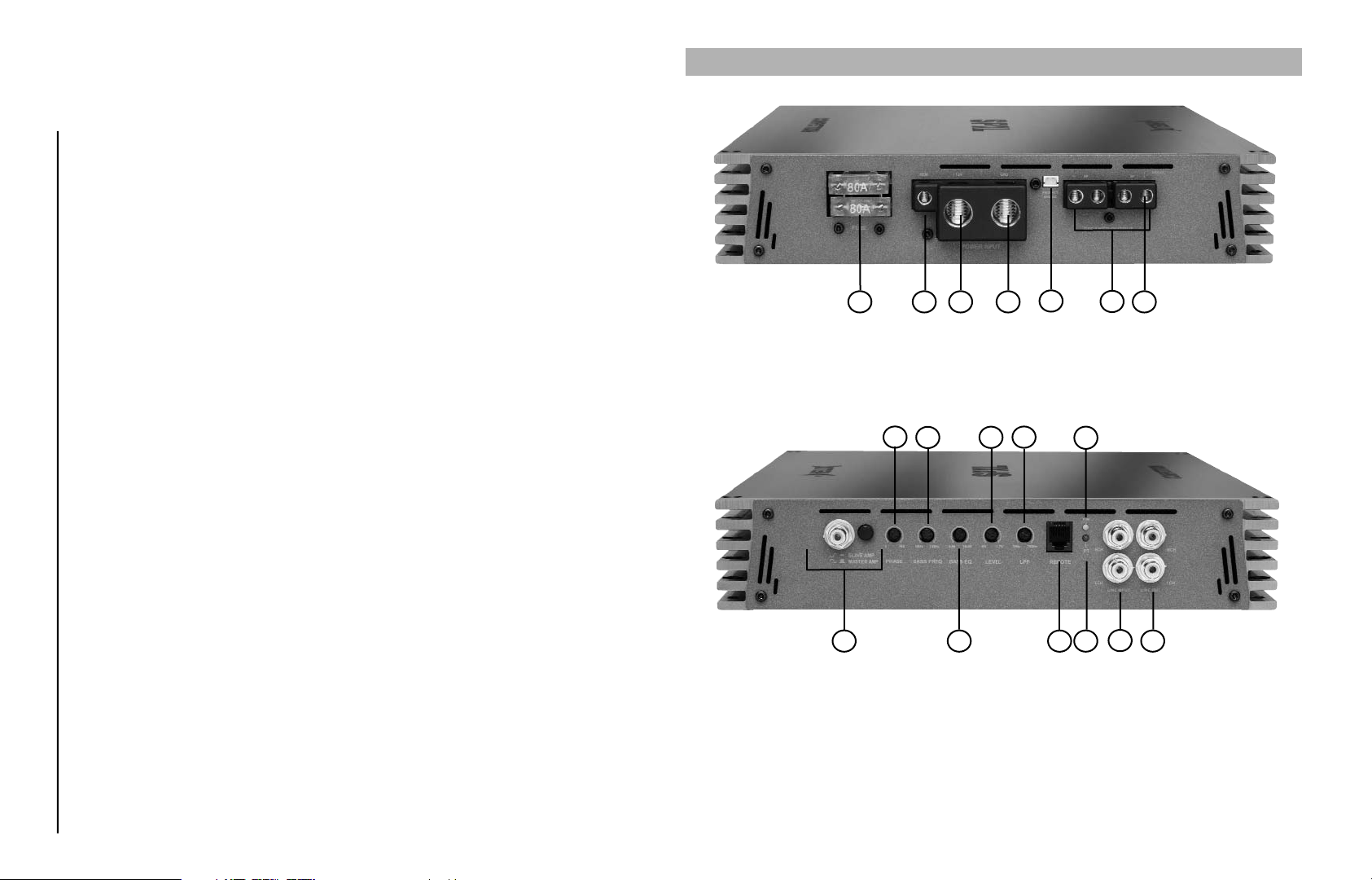
AUSSTATTUNG UND BEDIENELEMENTE SPXL 1000
Sicherungen 2 x 80 Ampere
1
Anschluss Remoteleitung
2
Anschluss Batteriekabel
3
14
12
Signaleingänge
8
Signalausgänge
9
Levelregler für Eingangsempfindlichkeit
10
Regler für Bassanhebung
11
Regler für Mittenfrequenz der Bassanhebung
12
Frequenzeinstellregler für Tiefpass
13
7
4321 6
Anschluss Massekabel
4
Lautsprecheranschlussklemme
5
Lautsprecheranschluss für Master and Slave Modus
6
Protect Bridge Kurzschlussbrücke
7
13
10
11 18
14
15
16
17
18
17
15
Phasenregler 0 - 180°
Bass Remote Anschluss
Master and Slave Modus
Power LED
Protection LED
5
8
916
2
Page 3
1 Sicherung
Die Eingangssicherung schützt vor einem geräteinternen Fehler.
Zusätzlich muss die Endstufe mit einer Sicherung in Nähe der Batterie
(max. 30 cm entfernt) abgesichert werden. Der Sicherungswert hierfür beträgt 2 x 80 Ampere für die Competition SPXL 1000.
2 Anschluss Remoteleitung
Die Remoteleitung wird mit der Steuerleitung des Steuergerätes
(Radio) verbunden. Dieser ist nur aktiviert, wenn das Steuergerät
EIN-geschaltet ist. Somit
ein-und ausgeschaltet.
3 Anschluss Batteriekabel
Das +12V-Versorgungskabel ist am Pluspol der Batterie anzuschließen. Empfohlener Querschnitt: min. 25 mm2.
4 Anschluss Massekabel
Das Massekabel sollte am zentralen Massepunkt (dieser befindet
sich dort wo der Minuspol der Batterie zum Metallchassis des Kfz
geerdet ist) oder an einer blanken, von Lack
des Kfz-Chassis angeschlossen werden.
5 Lautsprecheranschlussklemmen
Zum Anklemmen der Lautsprecherleitungen, siehe Anschlussdiagramme Seite 4
Verbinden Sie niemals die Lautsprecherleitungen mit der KfzMasse (Fahrzeugkarosserie). Dieses kann Ihren Verstärker
zerstören.
Achten Sie darauf, dass alle Lautsprechersysteme phasenrichtig
angeschlossen sind, d. h. Plus zu Plus und Minus zu Minus. Vertauschen von Plus und Minus hat einen Totalverlust der Basswiedergabe zu Folge. Der Pluspol ist bei den meisten Lautsprechern
gekennzeichnet.
Die Impedanz sollte 1 Ohm nicht unterschreiten, da sonst eine zu
hohe Wärmeentwicklung den Verstärker zum Abschalten bringen
kann.
6 Lautsprecheranschluss für Master and Slave Modus
Siehe Anschlussdiagramm S. 4 und Erläuterungen S. 3, Punkt 16.
7 Protect Bridge Kurzschlussbrücke
Um im Wettkampfeinsatz (60 - 80 Hz Testton) auch für eine niederohmige Subwooferkombination kurzzeitig maximale Leistung aus der
Master-and-Slave-Kombination zu erreichen, ohne dass die
Schutzschaltung aktiviert wird, lässt sich diese durch Brücken der
Protect-Bridge-Kontakte abschalten. Diese dürfen auf keinen Fall im
Betrieb mit Musiksignalen gebrückt werden.
wird der Verstärker mit dem Steuergerät
resten befreiten Stelle
8 Signaleingänge
Der SPXL-Verstärker hat RCA-Anschlüsse zum Kontaktieren von
Cinchkabeln, die mit den Vorverstärkerausgängen der LineOutputs des Steuergerätes oder eines Vorverstärkers verbunden
werden. Diese Anschlüsse sind
Übertragung zu gewährleisten.
9 Signalausgänge
Full Range Cinch Ausgänge zur Ansteuerung weiterer Verstärker.
10 Levelregler für Eingangsempfindlichkeit
Mit Hilfe dieser Regler kann die Eingangsempfindlichkeit der
Kanäle an die Ausgangsspannung des angeschlossenen Steuergerätes angepasst werden. Diese Regler sind keine
Lautstärkeregler, sondern dienen nur der Anpassung. Der
Regelbereich ist 200 mV bis 6 V.
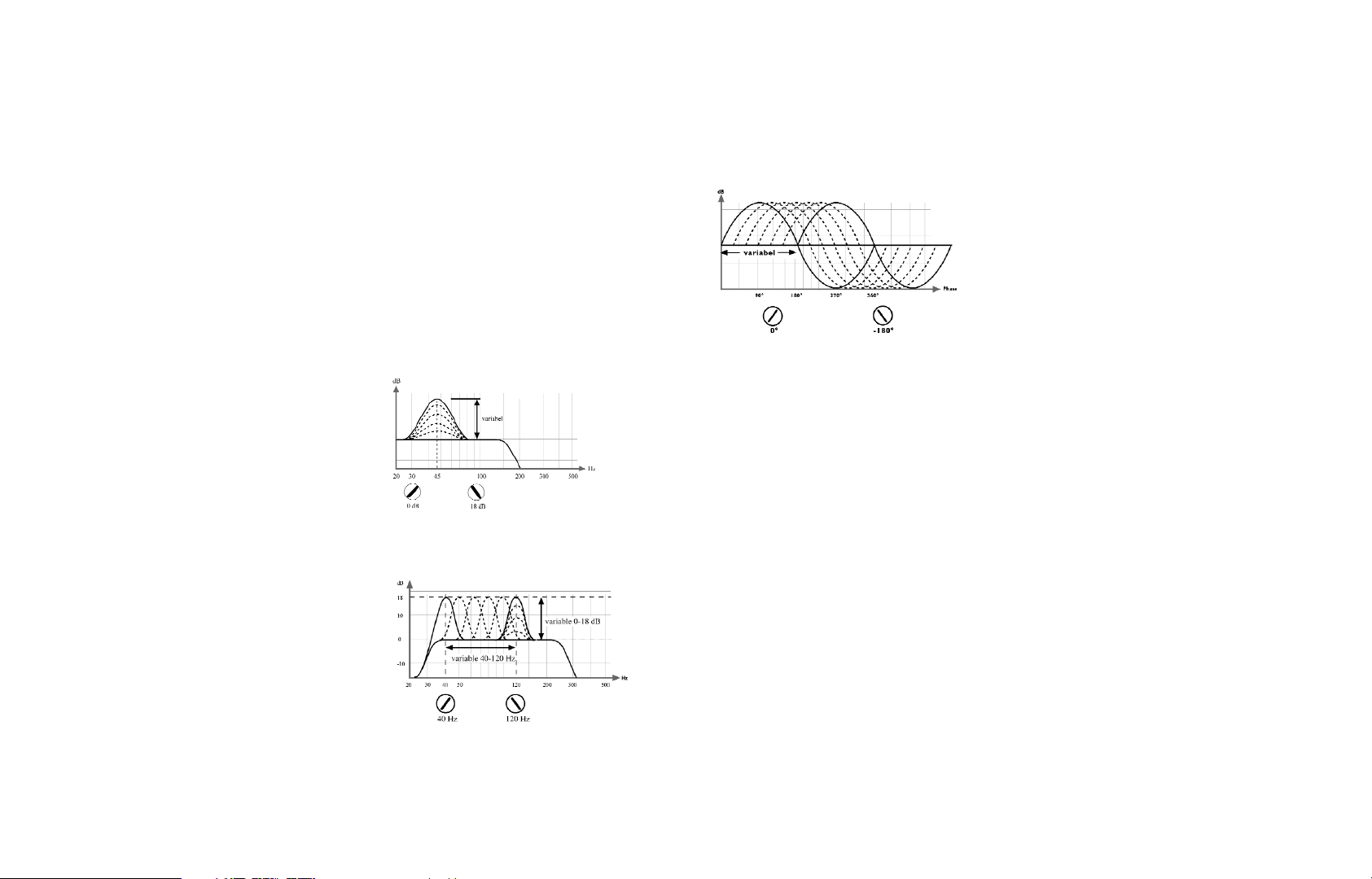
11 Bassboost - Pegelregler zur Anhebung des Basssignals
Mit Hilfe dieses Reglers kann das Basssignal bei der durch Regler
Nr. 12 eingestellten Mittenfrequenz von 0 bis 18 dB angehoben
werden.
12 Einstellung der Mittenfrequenz
Mit Hilfe des Reglers 12 kann eine Frequenz von 40 - 120 Hz eingestellt werden, die mit Hilfe des Reglers 11 von 0 - 18 dB angehoben werden kann.
13 Frequenzeinstellregler für den Tiefpass
Regler zur Einstellung der Trennfrequenz von 35 Hz bis 250 Hz.
14 Phasenregler
Mit Hilfe dieses Reglers kann die Phase des Basssignals um bis zu
180 Grad verschoben werden, um so eine optimale
Laufzeitanpassung zu den anderen Kanälen zu erreichen.
vergoldet um eine bessere NF-
15 Bass-Remote Anschluss
Mit der Bass-Remote Control lässt sich die Basslautstärke vom
Fahrersitz aus kontrollieren.
16 Master und Slave Modus
Bei der SPXL 1000 handelt es sich um eine „real-mono“ Endstufe,
die sich über den Master und Slave Modus mit einer zweitenSPXL
1000 verschalten lässt und somit die Leistung verdoppelt.
Um zwei Endstufen im Master und Slave Betrieb zu betreiben,
werden sie über die In/Out Buchse mit einem Cinchkabel verbunden. Die Endstufe, die auf Master geschalten ist, übernimmt nun
die komplette Regelung (Aktivweiche, Gain usw.) und liefert an
ihrer Bridge-Out-Lautprecheranschlussklemme (siehe Punkt 6 und
Anschlussdiagramm nächste Seite) das + Signal. Die Slavegeschaltete Endstufe liefert an ihrer Bridge-Out-Laustprecheranschlussklemme (siehe Punkt 6 und Anschlussdiagramm nächste
Seite) das – Signal für den Subwoofer.
Achtung: Bitte immer darauf achten das eine Endstufe auf
Master und die andere auf Slave geschalten ist. In diesem
Modus liegt die Minimalimpedanz bei 2 Ohm.
17 Power LED
Die grüne LED zeigt den Betriebszustand der Endstufe an.
18 Protection LED
Die rote LED zeigt Fehlfunktionen der Endstufe an.
Die SPXL-Verstärker sind mit verschiedenen elektronischen
Schutzschaltungen ausgestattet, die bei Überlastung,
Überhitzung, Kurzschluss an den Lautsprechern, aber auch bei zu
niederohmigem Betrieb oder mangelhafter Stromversorgung den
Verstärker abschalten.
Prüfen Sie in diesem Fall alle Anschlüsse auf Fehler, wie z. B.
Kurzschlüsse, fehlerhafte Verbindungen oder Falscheinstellungen
und Übertemperatur. Sollte sich der Verstärker nach der Beseitigung der Fehlerquelle nicht wieder einschalten lassen, liegt ein
Defekt vor und das Gerät muß mit Fehlerbeschreibung und Kaufbeleg zur Reparatur an den Händler zurückgegeben werden.
3
Page 4

ANSCHLUSS MASTER AND SLAVE MODUS SPXL 1000
TECHNISCHE DATEN SPXL 1000
Ausgangsleistung an 4 Ohm . . . . . . . . . . . . . . . . . . . . . . . . . . . . . . . 1 x 750/1275 Watt RMS/Musik
Ausgangsleistung an 2 Ohm . . . . . . . . . . . . . . . . . . . . . . . . . . . . . . . 1 x 1200/2040 Watt RMS/Musik
Ausgangsleistung an 1 Ohm . . . . . . . . . . . . . . . . . . . . . . . . . . . . . . . 1 x 1750/2975 Watt RMS/Musik
Frequenzbereich . . . . . . . . . . . . . . . . . . . . . . . . . . . . . . . . . . . . . . . . . . . . . . . . . . . 27 Hz - 250 Hz
Bassboost Pegelanhebung . . . . . . . . . . . . . . . . . . . . . . . . . . . . . . . . . . . . . . . . . . . . . . . . . .0 - 18 dB
Bassboost Einstellbereich der Mittenfrequenz . . . . . . . . . . . . . . . . . . . . . . . . . . . . . . . . . .40 - 120 Hz
Regelbereich Tiefpass . . . . . . . . . . . . . . . . . . . . . . . . . . . . . . . . . . . . . . . . . . . . . . . 35 Hz - 250 Hz
Klirrfaktor . . . . . . . . . . . . . . . . . . . . . . . . . . . . . . . . . . . . . . . . . . . . . . . . . . . . . . . . . . . . . < 0,33%
Geräuschspannungsabstand . . . . . . . . . . . . . . . . . . . . . . . . . . . . . . . . . . . . . . . . . . . . . . . . > 96 dB
Eingangsimpedanz . . . . . . . . . . . . . . . . . . . . . . . . . . . . . . . . . . . . . . . . . . . . . . . . . . . . . . . 50 kOhm
Eingangsempfindlichkeit . . . . . . . . . . . . . . . . . . . . . . . . . . . . . . . . . . . . . . . . . . . . . . . . 200 mV - 6 V
Sicherung . . . . . . . . . . . . . . . . . . . . . . . . . . . . . . . . . . . . . . . . . . . . . . . . . . . . . . . . .2 x 80 Ampere
Abmessungen (H x B x T) in mm . . . . . . . . . . . . . . . . . . . . . . . . . . . . . . . . . . . . . . . . 55 x 277 x 430
Gewicht netto . . . . . . . . . . . . . . . . . . . . . . . . . . . . . . . . . . . . . . . . . . . . . . . . . . . . . . . . . . . . 7,3 kg
4
Page 5

GARANTIEBESTIMMUNGEN
Helix-Produkte geniessen aufgrund ihres hohen Qualitätsniveaus
international einen ausgezeichneten Ruf. Daher gewähren wir
eine Garantiezeit von 2 Jahren.
Die Produkte werden während der gesamten Fertigung ständig
kontrolliert und geprüft. Bitte beachten Sie im Servicefall folgende Hinweise:
1. Die 2-jährige Garantiezeit beginnt mit Kauf des Produktes
und gilt nur für den Erstbesitzer.
Während der Garantiezeit beseitigen wir etwaige Mängel,
2.
nachweislich auf Material-oder Fabrikationsfehlern beruhen, nach unserer Wahl durch Austausch oder Nachbesserung der defekten Teile. Weitergehende Ansprüche,
insbesondere auf Minderung, Wandlung, Schadenersatz oder
Folgeschäden sind ausgeschlossen. Ersetzte Teile gehen in
das Eigentum von Audiotec Fischer über. Die Garantiezeit wird
von einer Garantieleistung durch uns nicht berührt.
3. Am Produkt dürfen keine unsachgemäßen Eingriffe vorgenommen worden sein.
4. Bei Inanspruchnahme der Garantie wenden Sie sich bitte
zuerst an Ihren Fachhändler. Sollte es notwendig sein, das
Produkt an uns einzuschicken, so beachten Sie bitte folgende Hinweise:
a) Das Produkt muss in einwandfreier Originalverpackung
verschickt werden.
Die Garantiekarte muss ausgefüllt dem Produkt beiligen.
b)
c) Das Produkt muss frachtfrei zugestellt werden, d. h.
Porto und Risiko gehen zu Ihren Lasten
d) Die Kaufquittung muss beiliegen.
5. Von der Garantie ausgenommen sind:
a) Transportschäden, sichtbar oder unsichtbar (Reklama-
tionen für solche Schäden müssen umgehend bei der
Transportfirma eingereicht werden)
b) Kratzer in Metallteilen, Frontabdeckungen usw. Diese
Defekte müssen innerhalb von 5 Tagen nach Kauf direkt
bei Ihrem Händler reklamiert werden.
c) Fehler, die durch fehlerhafte Aufstellung, falschen
schluss, unsachgemäße Bedienung, Beanspruchung
äußere gewaltsame Einwirkung entstanden sind.
d) Unsachgemäß reparierte oder geänderte Geräte, die von
anderer Seite als von uns geöffnet wurden.
e) Folgeschäden an fremden Geräten
f) Kostenerstattung bei Schadensbehebung durch Dritte
ohne unser vorheriges Einverständnis
g) Geräte mit entfernten Typenschildern oder Seriennummern.
die
An-
oder
Dear Customer,
congratulations on your purchase of this high-quality HELIX
Competition SPXL 1000 amplifier. This series highlights best
ENGLISH
quality, excellent manufacturing and state-of-the-art tech-
nology. After 27 years of experiences in the research &
development of audio products this amplifier generation
sets new standards. The attractive typical HELIX
Competition design makes this amplifier an outstanding
and top of the class product.
We wish you many hours of enjoyment with your new
HELIX amplifier.
Yours
AUDIOTEC FISCHER Team
www.audiotec-fischer.com
General installation instructions for HELIX amplifiers
To find out how HELIX amplifiers work best for you, read this
manual carefully and follow the instructions for installation. We
guarantee that this product has been checked for proper functioning before shipping.
Before you start installation, disconnect the car battery at the
minus pole. We would urge you to have the installation work carried out by a specialist as verification of correct installation and
connection of the unit is a prerequisite for warranty cover of the
HELIX amplifier.
Install your amplifier at a dry location where there is sufficient air
circulation to ensure adequate cooling of the equipment. For
safety reasons, the amplifier must be secured in a professional
manner. This is performed by means of four fixing screws screwed into a mounting surface offering sufficient retention and stability.
Before drilling the holes for the screws, carefully examine the area
around the installation position and make sure that there are no
electrical cables or components, hydraulic brake lines or any part
of the petrol tank located behind the mounting surface - otherwise these could be damaged. You should be aware of the fact that
such components may also be concealed in the double-skin trim
panels/mouldings.
General instruction for connecting the amplifiers
The HELIX amplifiers may only be installed in motor vehicles
which have a 12-volt minus pole connected to the chassis ground.
Any other system could cause damage to the amplifier and the
electrical system of the vehicle.
The plus cable from the battery for the complete system should be
provided with a main fuse at a distance of max. 30 cm from the
battery. The value of the fuse is calculated from the maximum total
current input of the car audio system.
Install the cabling in a manner which precludes any danger of the
leads being exposed to shear, crushing or rupture forces. If there are
sharp edges in the vicinity (e.g. holes in the bodywork) all cables
must be cushioned and protected to prevent fraying.
Never lay the power supply cables adjacent to leads and lines
connecting other vehicle equipment (fan motors, fire detection
modules, gas lines etc.).
In order to ensure safe installation, use only high-quality connections
and materials. Ask your dealer for high quality accessories.
5
Page 6

EQUIPMENT FEATURES AND CONTROL ELEMENTS SPXL 1000
Fuses 80 amperes
1
Connecting the remote lead
2
Connecting the battery cable
3
14
Signal inputs
8
Signal outputs
9
Level controls for input sensitivity
10
Bass boost control
11
Control to raise the center frequency
12
Frequency control for low pass
13
4321 6
Connecting the ground cable
4
Speaker terminal
5
Speaker connector for Master and Slave Mode
6
Protect Bridge
7
13
12
10
11 18
Phase control 0 - 180°
14
Bass remote connector
15
Master and Slave Mode
16
On LED
17
Protection LED
18
7
15
17
5
8
916
1 Fuse
The input fuse provides protection against an internal equipment
fault. In addition, the amplifier must be protected by a further line
fuse located in the vicinity of the battery (max. distance from battery: 30 cm). For this fuse the rating is 2 x 80 amperes.
2 Connecting the remote lead
The remote lead is connected to the automatic antenna (aerial
positive) output of the head unit (radio). This is only activated if
the head unit is switched ON. Thus the amplifier is switched on
and off with the head unit.
3 Connecting the battery cable
Connect the +12 V power cable to the positive terminal of the
battery. Recommended cross section: min. 25 mm
4 Connecting the ground cable
The ground cable should be connected to a central ground refe-
rence point (this is located where the negative terminal of the
battery is grounded at the metal body of the vehicle), or to a
bright bare-metal location on the vehicle chassis, i. e. an area
which has been cleaned of all paint residues.
5 Speaker terminals
To connect the speaker cables. See figures on page 6.
Never connect the loudspeaker cables with the car chassis gound. It damages your amplifier.
Ensure that the loudspeaker systems are correctly connected
(phase), i. e. plus to plus and minus to minus. Exchanging plus
and minus causes a total loss of bass reproduction.The plus pole
is indicated on most speakers.
The impedance per channel should not be lower than
1 ohm as overheating could cause a shut down of the amplifier.
6 Speaker connection for Master and Slave Mode
See figures on this page and instructions following No. 16
7 Protect Bridge
To reach maximum power from the Master and Slave Mode during
competition (60 to 80 Hz test tone) for a low-ohmic subwoofer
combination, the protection circuit can be deactivated by bridging
the Protect Bridge contacts.
Don’t bridge contacts when operated with music signals.
8 Signal inputs
The SPXL amplifier has RCA connectors for RCA cables that can
2
.
be connected with the pre-amplifier output of the line-outputs of
the headunit or with a pre-amplifier. This connectors are gold-plated to ensure a better signal transmission.
9 Signal outputs
Full range RCA outputs to connect other amplifiers.
10 Level controls for input sensitivity
These controls can be used to match the input sensitivity of the
individual channels to the output voltage of the connected head
unit. These controls are not volume controls and are solely intended for the purpose of sensitivity trimming. The control range
extends from 200 mV to 6 V.
11 Bassboost control
To raise the bass signal from 0 to 18 dB at the center frequency
being adjusted by control 12.
12 Control to raise the center frequency
This control adjust the frequency from 40 to 120 Hz, which could
be raised from 0 - 18 dB by control 11.
13 Lowpass control
To adjust the crossover frequency from 35 Hz to 250 Hz.
6
Page 7

14 Phase control
This control enables the phase of the bass signal to be shifted by
180° in order to achieve optimum delay equalization with the
other channels.
15 Remote bass control connector
To control the bass level from the driver position.
16 Master and Slave Mode
The SPXL 1000 is a „real-mono“ amplifier. In order to double the
power it can be connected to a second SPXL 1000 via the Master
and Slave Mode. In order to operate two amplifiers in this mode,
they must be connected with a RCA cable (In/Out). Amplifier1
(Master) takes over the complete control (active crossover, gain
etc.) and provides the +signal at the bridge out speaker connector (see No. 6 and figure page 7). Amplifier 2 (Slave) provides the
-signal at its bridge out speaker connector for the subwoofer (see
No. 6 and figure page 7).
Attention: Make sure that amplifier1 is switched on
master and amplifier 2 is switched on slave. In this mode
the minimum impedance is 2 ohms.
17 Power LED
Shows the operation mode of the amplifier.
18 Protection LED
The red LED indicates malfunctions of the amplifier.
The SPXL amplifier has several electronic protection circuits that
shut off the amplifier at overheating, overloading, short-circuit on
loudspeaker, low-ohmic mode or defective power supply.
Please check for connecting failures such as short-circuits, wrong
connections and over-temperature.
If the amplifier does not turn on it is defect and has to be send to
your local authorized dealer for repair service. A detailed description of the malfunction and the purchase receipt has to be attached.
CONNECTION OF MASTER AND SLAVE MODE SPXL 1000
WARRANTY REGULATION
Due to the high quality standard Helix products achieved an
excellent international reputation. Therefore we grant a warranty period of 2 years.
The products checked and tested carefully during the entire production process. In the case of service note the following:
1) The 2 years warranty period commences with the purchase
of the product and is applicable only to the original owner.
2) During the warranty period we will rectify any defects
due to faulty material or workmanship by replacing or repai
ring the defective part at our decision.
Further claims, and in particular those for price reduction,
cancellation of sale, compensation for damages or subse
quential damages, are excluded. The warranty period is not
altered by the fact that we have carried out warranty work.
3) Unauthorized tampering with the product will invalidate this
warranty.
4) Consult your authorized dealer first, if warranty service is
needed. Should it be necessary to return the product to the
factory, please insure that
a) the product is packed in original factory packing in
good condition
b) the product is shipped prepaid, i.e. at your expense
and risk
c) the receipt/invoice as proof of purchase is enclosed
5) Excluded from the warranty are:
a) Shipping damages, either readily apparent or concea-
led (claims for such damages must be immediately
notified to the forwarding agent).
b) Scratches in metal parts, front panels or covers etc.
This must be notified to your dealer within 5 days of purchase.
c) Defects caused by incorrect installation or connec-
tion, by operation errors, by overloading or by external force.
d) Products which have been repaired incorrectly or
modified or where the product has been opened by
other persons than us.
e) Consoquential damages to other equipments.
f) Reimbursement when repairing damages by third
parties without our previous permission.
7
Page 8

TECHNICAL DATA SPXL 1000
Cont. power rating at 4 Ohms . . . . . . . . . . . . . . . . . . . . . . . . . . . . . 1 x 750/1275 Watts RMS/Music
Cont. power rating at 2 Ohms . . . . . . . . . . . . . . . . . . . . . . . . . . . . . 1 x 1200/2040 Watts RMS/Music
Cont. power rating at 1 Ohm . . . . . . . . . . . . . . . . . . . . . . . . . . . . . . 1 x 1750/2975 Watts RMS/Music
Frequency response . . . . . . . . . . . . . . . . . . . . . . . . . . . . . . . . . . . . . . . . . . . . . . . . . 27 Hz - 250 Hz
Bassboost . . . . . . . . . . . . . . . . . . . . . . . . . . . . . . . . . . . . . . . . . . . . . . . . . . . . . . . . . . . . . 0 - 18 dB
Setting range lowpass . . . . . . . . . . . . . . . . . . . . . . . . . . . . . . . . . . . . . . . . . . . . . . . 35 Hz - 250 Hz
Total harmonic distortion (THD) . . . . . . . . . . . . . . . . . . . . . . . . . . . . . . . . . . . . . . . . . . . . . < 0,33%
Signal to noise ratio . . . . . . . . . . . . . . . . . . . . . . . . . . . . . . . . . . . . . . . . . . . . . . . . . . . . . . > 96 dB
Input impedance . . . . . . . . . . . . . . . . . . . . . . . . . . . . . . . . . . . . . . . . . . . . . . . . . . . . . . . 50 kOhms
Input sensitivity . . . . . . . . . . . . . . . . . . . . . . . . . . . . . . . . . . . . . . . . . . . . . . . . . . . . . .200 mV - 6 V
Fuse . . . . . . . . . . . . . . . . . . . . . . . . . . . . . . . . . . . . . . . . . . . . . . . . . . . . . . . . . . . . .2 x 80 Ampere
Dimensions (H x W x D) in mm . . . . . . . . . . . . . . . . . . . . . . . . . . . . . . . . . . . . . . . . . 55 x 277 x 430
Weight net. . . . . . . . . . . . . . . . . . . . . . . . . . . . . . . . . . . . . . . . . . . . . . . . . . . . . . . . . . . . . . . 7,3 kg
Gewerbegebiet Lake II · Hünegräben 26 · D-57392 Schmallenberg
Tel.: ++49 (0) 29 72-97 88 0 · Fax: ++49 (0) 29 72-97 88 88
E-mail: helix@audiotec-fischer.com · Internet: www.audiotec-fischer.com
8
www.audiotec-fischer.com
 Loading...