

Page 1

deutsch / english
P TWO
2-Kanal High-Res Verstärker mit integrierter aktiver
Frequenzweiche und digitalem Signaleingang
2-channel High-Res amplier with integrated active
crossover and digital signal input
Page 2

Herzlichen Glückwunsch!
Sehr geehrter Kunde,
Wir gratulieren Ihnen zum Kauf dieses hochwertigen HELIX Verstärkers.
Audiotec Fischer setzt mit der HELIX P TWO neue
Maßstäbe im Bereich der Verstärkertechnik.
Dabei protieren Sie als Kunde direkt von unserer
mehr als 30-jährigen Erfahrung in der Forschung
und Entwicklung von Audiokomponenten.
Allgemeine Hinweise
Allgemeines zum Einbau von HELIX-Komponenten
Um alle Möglichkeiten des Produktes optimal ausschöpfen zu können, lesen Sie bitte sorgfältig die
nachfolgenden Installationshinweise. Wir garantieren, dass jedes Gerät vor Versand auf seinen einwandfreien Zustand überprüft wurde.
Vor Beginn der Installation unterbrechen Sie
den Minusanschluss der Autobatterie.
Wir empfehlen Ihnen, die Installation von einem
Einbauspezialisten vornehmen zu lassen, da der
Nachweis eines fachgerechten Einbaus und Anschlusses des Gerätes Voraussetzung für die Garantieleistungen sind.
Dieser Verstärker wurde von uns nach neuesten
technischen Erkenntnissen entwickelt und zeichnet
sich durch hervorragende Verarbeitung und eine
überzeugende Anwendung ausgereifter Technologien aus.
Viel Freude an diesem Produkt wünscht Ihnen das
Team von
AUDIOTEC FISCHER
sind. Diese könnten sonst beschädigt werden. Achten Sie bitte darauf, dass sich solche Teile auch in
der doppelten Wandverkleidung verbergen können.
Allgemeines zum Anschluss des P TWO Verstärkers
Der Verstärker darf nur in Kraftfahrzeuge eingebaut
werden, die den 12 V-Minuspol an Masse haben.
Bei anderen Systemen können der HELIX Verstärker und die elektrische Anlage des Kfz beschädigt
werden. Die Plusleitung für die gesamte Anlage
sollte in einem Abstand von max. 30 cm von der
Batterie mit einer Hauptsicherung abgesichert werden. Der Wert der Sicherung errechnet sich aus der
maximalen Stromaufnahme der Car-Hi Anlage.
Installieren Sie Ihren Verstärker an einer trocke-
nen Stelle im Auto und vergewissern Sie sich, dass
der Verstärker am Montageort genügend Kühlung
erhält. Montieren Sie das Gerät nicht in zu kleine,
abgeschlossene Gehäuse ohne Luftzirkulation
oder in der Nähe von wärmeabstrahlenden Teilen
oder elektronischen Steuerungen des Fahrzeuges.
Im Sinne der Unfallsicherheit muss der Verstärker
professionell befestigt werden. Dieses geschieht
über Schrauben, die in eine Montageäche eingeschraubt werden, die wiederum genügend Halt
bieten muss.
Bevor Sie die Schrauben im Montagefeld befestigen, vergewissern Sie sich, dass keine elektrischen
Kabel und Komponenten, hydraulische Bremslei-
tungen, der Benzintank etc. dahinter verborgen
2
Verwenden Sie zum Anschluss des Verstärkers
an die Stromversorgung des Fahrzeugs ausschließlich geeignete Kabel mit ausreichendem Kabelquerschnitt. Die Sicherungen im
Verstärker dürfen nur mit den gleichen Werten
(3 x 30 A) ersetzt werden, um eine Beschädigung des Gerätes zu verhindern. Höhere Werte
können zu gefährlichen Folgeschäden führen!
Die Kabelverbindungen müssen so verlegt sein,
dass keine Klemm-, Quetsch- oder Bruchgefahr besteht. Bei scharfen Kanten (Blechdurchführungen)
müssen alle Kabel gegen Durchscheuern gepolstert sein. Ferner darf das Versorgungskabel niemals
mit Zuleitungen zu Vorrichtungen des Kfz (Lüftermotoren, Brandkontrollmodulen, Benzinleitungen
etc.) verlegt werden.
Page 3

Anschluss- und Bedienelemente
1 3 5 6 7 9 10 11 122
4
Highlevel Input
1
Hochpegel-Lautsprechereingang zum An-
schluss von Werksradios oder Radios ohne
Vorverstärkerausgänge.
Line Input
2
Cinch-Eingänge zum Anschluss eines
Vorverstärkersignals.
Clipping LED
3
Diese LED leuchtet rot, wenn einer der Ein-
gänge übersteuert wird.
Gain
4
Regler zum Einstellen der Eingangsemp-
ndlichkeit des Line, Highlevel und Optical
Inputs.
Remote Control
5
Eingang zum Anschluss der mitgelieferten
Fernbedienung zur Lautstärkeregelung.
HPF Frequenz
6
Regler zum Einstellen des Hochpasslters
von 15 Hz bis 4.000 Hz.
8
X-Over
7
Schalter zum Aktivieren der verschiedenen
Filter.
LPF Frequenz
8
Regler zum Einstellen des Tiefpasslters von
15 Hz bis 4.000 Hz.
Bass Boost Frequenz
9
Regler zum Einstellen der Mittenfrequenz
des Bass Boost von 40 Hz bis 120 Hz.
Bass Boost Gain
10
Regler zum Einstellen der Bassanhebung
von 0 bis 9 dB.
Input Mode
11
Schalter zur Verteilung der Eingangssignale
auf die jeweiligen Verstärkerkanäle.
Optical Input
12
Optischer Eingang im SPDIF-Format für digi-
tale Stereosignale.
13
Output Channels
13
Lautsprecherausgänge für den Anschluss
von Lautsprechersystemen.
Fuse LED
14
Die Fuse LED zeigt den Betriebszustand des
Verstärkers an.
GND
15
Anschluss des Massekabels (Minuspol der
Batterie oder Fahrzeugchassis).
14 1715 16 18
REM
16
Anschluss für die Remoteleitung.
+12 V
17
Anschluss für das Versorgungsspannungs-
kabel +12 V der Batterie.
Auto Remote
18
Dient zum Aktivieren bzw. Deaktivieren der
automatischen Einschaltung des Verstärkers.
3
Page 4
Inbetriebnahme und Funktionen
Highlevel Input
1
2-Kanal Hochpegel-Lautsprechereingang. Mit Hilfe dieses Eingangs kann der Verstärker direkt an
die Lautsprecherausgänge eines Werks- / Nachrüstradios angeschlossen werden, sofern dieses
nicht über Vorverstärkerausgänge verfügt. Der
Highlevel-Eingang verfügt über den ADEP-Schaltkreis (Advanced Diagnostics Error Protection), der
dafür sorgt, dass der Verstärker auch von OEM
Radios als Lautsprecher erkannt wird und somit im
Werksradio keine Funktionen deaktiviert werden
und kein Eintrag im Fehlerspeicher des Fahrzeugs
erzeugt wird.
Bei Verwendung dieses Eingangs schaltet der Verstärker bei allen handelsüblichen Radios automatisch ein, so dass dieser nicht über den RemoteEingang (REM) eingeschaltet werden muss.
Achtung: Verwenden Sie zum Anschluss ausschließlich den mitgelieferten Stecker mit integrierten Schraubklemmen.
Achtung: Der Highlevel- und der Vorverstärker-
signaleingang eines einzelnen Kanals darf nicht
gleichzeitig genutzt werden, da dies zu Schäden
an ihrem Autoradio führen kann. Es ist aber zuläs-
sig, an einem Kanal den Highlevel- und an einem
anderen Kanal den Vorverstärkersignaleingang zu
verwenden.
Line Input
2
2-Kanal Vorverstärkereingang zum Anschluss von
Signalquellen, wie z.B. Radios, die mit dem/den
Vorverstärkerausgang/-ausgängen bzw. Line Outputs der Signalquelle verbunden werden können.
Achtung: Der Highlevel- und der Vorverstärker-
signaleingang eines einzelnen Kanals darf nicht
gleichzeitig genutzt werden, da dies zu Schäden
an ihrem Autoradio führen kann. Es ist aber zuläs-
sig, an einem Kanal den Highlevel- und an einem
anderen Kanal den Vorverstärkersignaleingang zu
verwenden.
Gain
4
Mit Hilfe dieses Reglers kann die Eingangsempndlichkeit an die Ausgangsspannung des angeschlossenen Radios angepasst werden. Dieser Regler ist
kein Lautstärkeregler, sondern dient nur der Anpassung. Der Regelbereich des Cinch-Eingangs (Line
Input) liegt zwischen 2 - 8 Volt, des Hochpegeleingangs (Highlevel Input) zwischen 5 - 20 V und 0 12 dB für den optischen Eingang (Optical Input).
Sofern die Lautsprecherausgänge eines üblichen
Radios verwendet werden (Highlevel), empfehlen
wir eine Einstellung von ca. 9 Volt. Dafür stellen Sie
den Drehregler vom Linksanschlag aus im Uhrzei-
gersinn etwa auf die 9 Uhr-Position ein.
Remote Control
5
Eingang zum Anschluss der im Lieferumfang enthaltenen Fernbedienung. Mit Hilfe dieser Fernbedienung lässt sich die Lautstärke kontrollieren.
Hinweis: Die Lautstärkeregelung per Fernbedienung ist ausschließlich im Bandpass-Modus möglich.
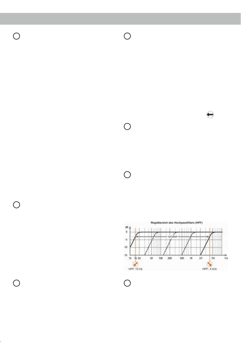
HPF Frequenz
6
Mit Hilfe dieses Reglers kann das Hochpasslter
von 15 Hz bis 4.000 Hz eingestellt werden.
Dieser Regler ist aktiviert, wenn der X-Over Schal-
ter auf HPF (Hochpasslter) oder BPF (Bandpass)
eingestellt ist. Ist die Schalterstellung BPF (Bandpass) gewählt muss dieser zwingend eingestellt
werden.
Clipping LED
3
Diese LED leuchtet rot, wenn einer der Line Inputs,
der Highlevel Inputs oder der Optical Input über-
steuert wird. Sofern diese LED aueuchtet, muss
die Eingangsempndlichkeit über den Regler 4
(Gain) abgesenkt werden, bis die LED erlischt.
4
X-Over
7
Zur Umschaltung der internen, aktiven Frequenzweichen auf Hochpass, Fullrange oder Bandpass.
Wird der X-Over Schalter auf HPF (Hochpassl-
ter) gestellt, so kann mit Hilfe des Reglers 6 die
Übernahmefrequenz für den Hochpass eingestellt
werden. Bei Schalterstellung FULL (Fullrange) ist
die interne Frequenzweiche nicht aktiv. Bei Schal-
Page 5
terstellung BPF (Bandpass) ist das Hochpasslter
immer aktiv. Das heißt, es wird in jedem Fall ein
Bandpass gebildet.
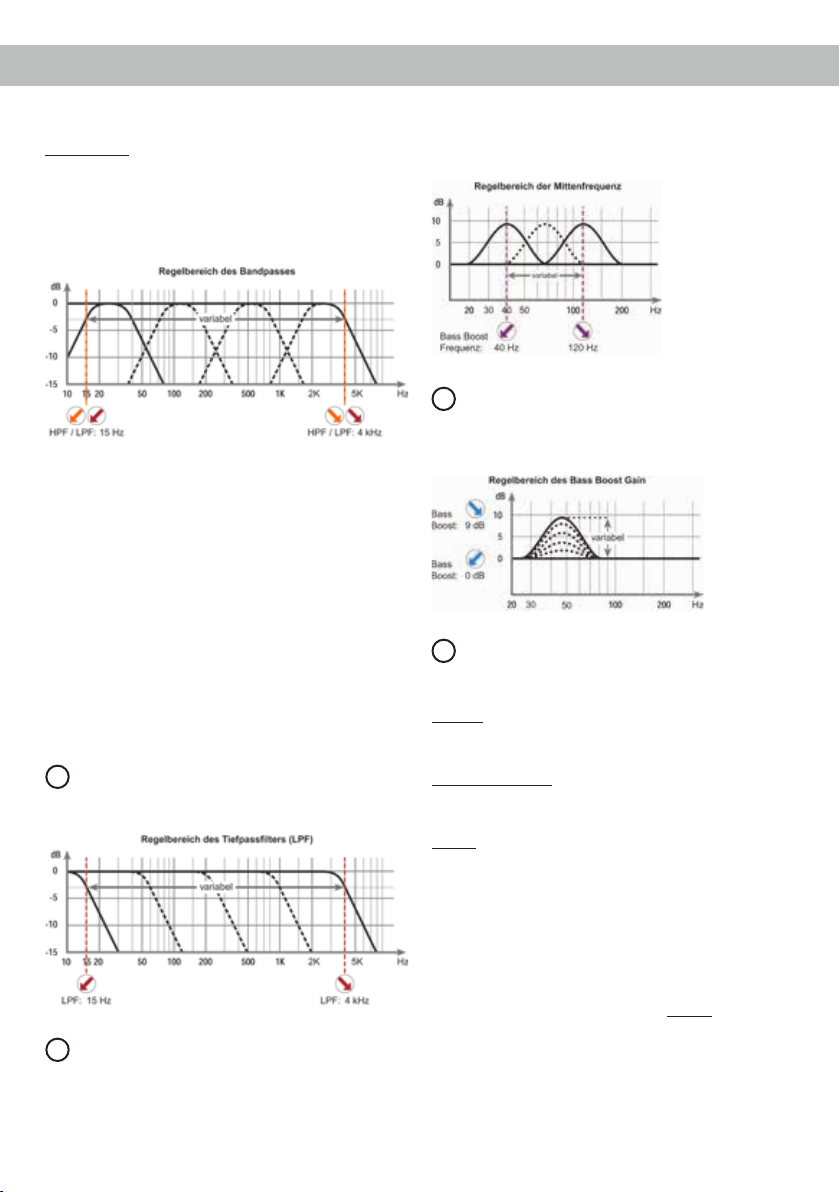
Mit dem Regler 6 wird der Hochpass und mit dem
Regler 8 der Tiefpass eingestellt. So kann jeder
beliebige Bandpass zwischen 15 Hz und 4.000 Hz
eingestellt werden.
Achtung: Bitte vergewissern Sie sich, dass beim
Einstellen eines Bandpasses die Übernahmefre-
quenzen von Hoch- und Tiefpass mindestens zwei
Oktaven auseinander liegen, um einen Pegelverlust
zu vermeiden! Das heißt: Wird das Tiefpasssignal
z.B. auf 320 Hz eingestellt, so sollte der Hochpass
um mindestens zwei Oktaven tiefer auf ca. 80 Hz
eingestellt werden. (1 Oktave = Frequenzverdopp-
lung oder Frequenzhalbierung).
Beim Anschluss eines Basslautsprechers empfehlen wir, den Hochpassregler (Regler 6) als regel-
baren Subsoniclter / tieffrequenten Hochpasslter
zu benutzen oder auf Linksanschlag (15 Hz) zu dre-
hen, um so einen Subsoniclter zu erhalten.
LPF Frequenz
8
Mit Hilfe dieses Reglers kann das Tiefpasslter von
15 Hz bis 4.000 Hz eingestellt werden.
Bass Boost Frequenz
9
Mit Hilfe dieses Reglers kann die Mittenfrequenz
des Bass Boost von 40 Hz bis 120 Hz eingestellt
werden. Mit dem Regler 10 kann diese dann um
0 bis 9 dB angehoben werden. Dies ist sinnvoll,
wenn bestimmte Frequenzen des Subwoofers oder
Kickbasses hervorgehoben oder korrigiert werden
sollen.
10
Bass Boost Gain
Mit Hilfe dieses Reglers kann die mit Regler 9 eingestellte Bassmittenfrequenz um 0 bis 9 dB angehoben werden.
11
Input Mode
Dieser Schalter dient zur Verteilung der Eingangssignale auf die jeweiligen Verstärkerkanäle.
Stereo: Bei Radios mit einem Stereoausgang wird
jeder der Lautsprecherausgänge mit dem dazuge-
hörigem Eingangssignal versorgt.
Stereo Summed: Bei Radios mit einem Stereoaus-
gang wird aus den Eingangssignalen von Kanal A
und B ein Summensignal gebildet.
Mono: Wird nur der Cinch- oder Highlevel-Eingangskanal A belegt, werden beide Kanäle des
Verstärkers mit diesem Signal versorgt. D.h. in diesem Modus wird das Eingangssignal von Kanal A
parallel auf Kanal B weitergeleitet. Bitte beachten
Sie, dass sich der Balanceregler des Steuergerätes
somit gleichermaßen auf Kanal B auswirkt, wie auf
Kanal A.
Hinweis: Der Optical Input liefert immer ein Stereo-
signal. Wird dieser als Signaleingang genutzt, ist je
nach Anwendungsfall die Schalterstellung „Stereo“
oder „Stereo Summed“ zu wählen.
5
Page 6

Inbetriebnahme und Funktionen
12
Optical Input
Optischer Eingang im SPDIF-Format für den Anschluss an Signalquellen mit digitalem Ausgang.
Die „Sampling Rate“ dieses Eingangs muss zwischen 28 - 96 kHz liegen.
Dank des SPDIF Direct In-Schalters lässt sich die
Eingangsstufe der P TWO umgehen und ermöglicht
eine direkte Weiterleitung der Digitalsignale vom integrierten DA-Wandler zum internen Leistungsver-
stärker. Dazu muss der Verstärker geöffnet und der
SPDIF Direct In-Schalter auf „On“ sowie der X-Over
Schalter auf die Schalterposition „Full“ gestellt werden (Seite 6, Punkt SPDIF Direct In-Schalter).
Wichtig: Das digitale Audiosignal einer Quelle ist
üblicherweise nicht lautstärkegeregelt. Das bedeu-
tet, dass an den Ausgängen der P TWO der volle
Pegel anliegt. Dies kann im Extremfall die ange-
schlossenen Lautsprecher zerstören. Wir raten
deshalb dringend dazu nur lautstärkegeregelte Si-
gnalquellen anzuschließen!
Hinweis: Es können ausschließlich Stereosignale
und keine MP3- oder Dolby-codierten Daten verarbeitet werden!
Hinweis: Eine gleichzeitige Verwendung des optischen Eingangs zusammen mit den HochpegelSignaleingängen oder den Vorverstärker-Signalein-
gängen ist möglich.
13
Output Channels
Diese Anschlüsse dienen als Lautsprecherausgänge. Die Impedanz der Lautsprecher darf 2 Ohm
nicht unterschreiten.
14
Fuse LED
Die Fuse LED zeigt den Betriebszustand des Ver-
stärkers an.
Grün: Verstärker eingeschaltet und betriebsbereit.
Rot: Es besteht eine Fehlfunktion des Verstärkers,
die unterschiedliche Ursachen haben kann. Die
P TWO ist mit Schutzschaltungen gegen Über- und
Unterspannung, Kurzschluss am Lautsprecherausgang und Verpolung ausgestattet.
Prüfen Sie in diesem Fall alle Anschlüsse auf Fehler, wie z.B. Kurzschlüsse oder fehlerhafte Verbindungen. Sollte sich der Verstärker nach Beseitigung
der Fehlerquelle nicht wieder einschalten lassen,
liegt ein Defekt vor.
Rot blinkend: Überhitzung des Verstärkers. Die in-
terne Temperaturüberwachung schaltet das Gerät
6
ab, bis ein sicherer Betrieb wieder gewährleistet
werden kann.
Rot / grün blinkend: Sicherungen im Inneren des
Geräts zerstört. Prüfen Sie die Sicherungen und
tauschen diese gegebenenfalls aus. Die Sicherungen im Verstärker dürfen nur mit den gleichen
Werten (3 x 30 Ampere) ersetzt werden, um eine
Beschädigung des Gerätes zu verhindern. Höhere
Werte können zu gefährlichen Folgeschäden füh-
ren!
15
GND
Das Massekabel sollte am zentralen Massepunkt
(dieser bendet sich dort wo der Minuspol der Batterie zum Metallchassis des Kfz geerdet ist) oder an
einer blanken, von Lackresten befreiten Stelle des
Kfz-Chassis angeschlossen werden. Der empfohlene Querschnitt beträgt mindestens 16 mm².
16
REM
Die Remoteleitung wird mit dem Remote-Ausgang /
Antennenanschluss des Steuergerätes (Radio) verbunden. Dieser ist nur aktiviert, wenn das Steuer-
gerät eingeschaltet ist. Somit wird der Verstärker
mit dem Steuergerät ein- und ausgeschaltet. Dieser
Eingang muss nicht belegt werden, wenn der
Hochpegel-Lautsprechereingang (Highlevel Input)
benutzt wird.
17
+12 V
Das +12 V Versorgungskabel ist am Pluspol der
Batterie anzuschließen. Der empfohlene Querschnitt beträgt mindestens 16 mm².
18
Auto Remote
Die Einschaltung des Verstärkers erfolgt automatisch bei Ansteuerung über die Hochpegel-Lautsprechereingänge (Highlevel Input) oder sobald ein
Remote-Signal am Remote-Eingang (REM) anliegt.
Mit Hilfe des Auto Remote Schalters kann die automatische Einschaltung in Verbindung mit den
Hochpegel-Lautsprechereingängen aktiviert bzw.
deaktiviert werden. Die Deaktivierung sollte vor-
genommen werden, wenn es beispielsweise zu
Störgeräuschen beim Ein- und Ausschalten des
Verstärkers kommt.
Hinweis: Wird die automatische Einschaltung des
Verstärkers deaktiviert, muss der Remote-Eingang
belegt werden. Eine automatische Einschaltung
Page 7

über den Hochpegel-Lautsprechereingang ist dann
nicht mehr möglich.
SPDIF Direct In-Schalter
Mit Hilfe des SPDIF Direct In-Schalter im Inneren
des Geräts kann die Eingangsstufe der P TWO
umgangen werden und das am optischen Eingang
( Optical Input) anliegende Digitalsignal vom integ-
rierten DA-Wandler direkt zum internen Leistungs-
verstärker weitergeleitet werden.
Um die direkte Signalweiterleitung zu aktivieren,
muss das Gerät geöffnet und die Schalterposition
des SPDIF Direct In-Schalters geändert werden.
Dazu entfernen Sie bitte das Bodenblech indem Sie
die zehn Inbusschrauben lösen und erhalten so Zu-
griff auf den Schalter. Dieser bendet sich auf der
Platine in der Nähe des „Made in Germany“ Aufdrucks (siehe Markierung im nachfolgenden Bild).
Hinweis: Der Schalter beeinusst ausschließlich
die Signalführung des optischen Eingangs.
Hinweis: Für die direkte Signalweiterleitung muss
der Verstärker im Fullrange-Modus betrieben
werden. Ändern Sie dazu die Schalterposition
des X-Over Schalters auf „Full“ (Seite 4, Punkt 7;
X-Over).
Hinweis: Steht der Schalter auf „ON“, sind die
Highlevel- und Vorverstärker-Signaleingänge sowie
der Gain-Regler (4) ohne Funktion!
On: Umgehung der Eingangsstufe deaktiviert.
Off: Umgehung der Eingangsstufe aktiviert
(Werkseinstellung).
7
Page 8

Einbau und Installation
Die HELIX P TWO wird wie nachfolgend beschrieben an das Autoradio angeschlossen.
Achtung: Für die Durchführung der nachfolgenden
Schritte werden Spezialwerkzeuge und Fachwissen
benötigt. Um Anschlussfehler und Beschädigungen
zu vermeiden, fragen Sie im Zweifelsfall Ihren Einbauspezialisten und beachten Sie zwingend die
allgemeinen Anschluss- und Einbauhinweise (siehe
Seite 2).
1. Anschluss der Vorverstärkereingänge
Diese Eingänge (Line Input) können mit entsprechenden Kabeln (RCA / Cinch-Kabel) an
die Vorverstärker- / Lowlevel- / Cinch-Ausgänge des Radios angeschlossen werden.
Dabei müssen nicht zwingend beide Eingänge
belegt werden. Wird nur ein Kanal belegt, ist
der Kanal A zu verwenden und der Input Mode
Schalter auf „Mono“ zu stellen. Bei Belegung
beider Kanäle wählen Sie je nach Anwendungsfall bitte die Schalterstellung „Stereo“ oder „Stereo Summed“ (Seite 5, Punkt 11; Input Mode).
Die Einschaltautomatik des Verstärkers funktioniert nicht bei Verwendung des Line Input
oder dem Optical Input, so dass der RemoteEingang (REM) zwingend belegt werden muss.
Achtung: Der Highlevel- und der Vorverstär-
kersignaleingang eines einzelnen Kanals darf
nicht gleichzeitig genutzt werden, da dies zu
Schäden an ihrem Autoradio führen kann. Es ist
aber zulässig, an einem Kanal den High levelund an einem anderen Kanal den Vorverstärkersignaleingang zu verwenden.
2. Anschluss der Highlevel-Lautsprechereingänge
Die Hochpegel-Lautsprechereingänge (Highlevel Input) können direkt mit den Lautsprecher-
ausgängen des Werks- bzw. Nachrüstradios mit
Hilfe entsprechender Kabel (Lautsprecherkabel
mit max. 1 mm² Querschnitt) verbunden werden. Wir empfehlen folgende Kanalbelegung:
Kanal A = Links
Kanal B = Rechts
Dabei müssen nicht zwingend beide Eingänge
belegt werden. Wird nur ein Kanal belegt, ist
der Kanal A zu verwenden und den Input Mode
Schalter auf „Mono“ zu stellen. Bei Belegung
8
beider Kanäle wählen Sie je nach Anwendungsfall bitte die Schalterstellung „Stereo“ oder „Stereo Summed“ (Seite 5, Punkt 11; Input Mode).
Achten Sie bitte auf eine korrekte Polung!
Wenn Sie einen Anschluss verpolen, kann da-
durch die Funktion des Verstärkers beeinträchtigt werden. Bei Verwendung dieses Eingangs
muss der Remote-Eingang (REM) nicht belegt
werden, da sich der Verstärker automatisch einschaltet, sobald ein Lautsprechersignal anliegt.
3. Anschluss einer digitalen Signalquelle
Sofern Sie über eine Signalquelle mit op-
tischem Digitalausgang verfügen, kann diese
an den Verstärker angeschlossen werden. Die
Einschaltautomatik des Verstärkers funktioniert
bei Verwendung des Digitaleingangs nicht, so
dass der Remote-Eingang (REM) zwingend
belegt werden muss. Da der Optical Input immer ein Stereosignal liefert, ist in Abhängigkeit
zum jeweiligen Anwendungsfall der Input Mode
Schalter auf „Stereo“ oder „Stereo Summed“ zu
stellen (Seite 5, Punkt 11; Input Mode).
Wichtig: Das digitale Audiosignal einer Quelle
ist üblicherweise nicht lautstärkegeregelt. Das
bedeutet, dass an sämtlichen Ausgängen der
P TWO der volle Pegel anliegt. Dies kann im
Extremfall die angeschlossenen Lautsprecher
zerstören. Wir raten deshalb dringend dazu nur
lautstärkegeregelte Signalquellen anzuschlie-
ßen!
Hinweis: Die P TWO kann nur unkomprimierte,
digitale Stereo PCM-Signale mit einer Abta-
strate zwischen 28 kHz und 96 kHz verarbeiten.
Es können keine MP3- oder Dolby-codierten
Daten verarbeitet werden.
4. Konguration des optischen Signaleingangs (optional)
Sofern Sie eine digitale Signalquelle anschließen, haben Sie die Möglichkeit das Digitalsi-
gnal vom integrierten DA-Wandler direkt und
verlustfrei auf den internen Leistungsverstärker
zu routen. Um das direkte Routing zu aktivieren,
muss die Schalterposition des SPDIF Direct InSchalters auf „On“ (Seite 6, Punkt SPDIF Direct
In-Schalter) und des X-Over Schalters auf „Full“
geändert werden (Seite 4, Punkt 7; X-Over).
Hinweis: Der Schalter beeinusst ausschließ-
Page 9

lich die Signalführung des optischen Eingangs.
5. Einstellung der Eingangsempndlichkeit
Achtung: Es ist zwingend notwendig die
Eingangsempndlichkeit der P TWO an die
Signalquelle anzupassen, um Schäden am
Verstärker zu vermeiden.
Um die Eingangsempndlichkeit zu verändern, verwenden Sie den Drehregler (Seite 4,
Punkt 4; Gain). Die Einstellung dieses Reglers
beeinusst sowohl die Vorverstärkereingänge
(Line Input) als auch die Hochpegel-Lautsprechereingänge (Highlevel Input) sowie den optischen Eingang (Optical Input)!
Zur Anpassung der Eingangsempndlichkeit
führen Sie bitte die folgenden Schritte durch:
1. Schließen Sie während dieser Prozedur keine Lautsprecher an die Ausgänge des Verstärkers an.
2. Schalten Sie den Verstärker ein.
3. Drehen Sie die Lautstärke Ihres Radios / Ihrer digitalen Signalquelle auf 90 % der Gesamtlautstärke und spielen ein 1 kHz Testsignal (Vollaussteuerung 0 dB) ab.
4. Sollte die Fuse LED bereits leuchten, verrin-
gern Sie mit Hilfe des Drehreglers (Punkt 4,
Seite 4; Gain) die Eingangsempndlichkeit,
bis die Fuse LED erlischt.
5. Erhöhen Sie die Eingangsempndlichkeit
durch Rechtsdrehung bis die Fuse LED aufleuchtet. Drehen Sie nun den Drehregler
gegen den Uhrzeigersinn bis die Fuse LED
wieder erlischt.
Sofern die Lautsprecherausgänge eines üb-
lichen Radios verwendet werden (Highlevel),
empfehlen wir eine Einstellung von ca. 9 Volt.
Dafür stellen Sie den Drehregler vom Linksan-
schlag aus im Uhrzeigersinn etwa auf die 9 UhrPosition ein.
6. Anschluss der Stromversorgung
Vor dem Anschluss des +12 V Versorgungs-
kabels an das Bordnetz muss die Autobatterie abgeklemmt werden.
Das +12 V Stromkabel ist am Pluspol der Bat-
terie anzuschließen. Die Plusleitung sollte in
einem Abstand von max. 30 cm von der Batterie mit einer Hauptsicherung abgesichert werden. Der Wert der Sicherung errechnet sich aus
der maximalen Stromaufnahme der gesamten
Car-Hi Anlage (P TWO = max. 90 A RMS bei
12 V Bordnetz). Verwenden Sie bei kurzen
Leitungen (< 1 m) einen Querschnitt von mindestens 16 mm². Bei längeren Leitungen emp-
fehlen wir einen Querschnitt von 25 mm² bis
35 mm².Das Massekabel (gleicher Querschnitt
wie das +12 V Kabel) muss an einem blan-
ken, von Lackresten befreiten Massepunkt des
Kfz-Chassis oder direkt an dem Minuspol der
Autobatterie angeschlossen werden.
7. Anschluss des Remote-Eingangs
Der Remote-Eingang (REM) muss mit dem
Remote-Ausgang des Radios verbunden sein,
sofern die Vorverstärkereingänge oder der Di-
gitaleingang des Verstärkers als Signaleingänge / Signaleingang genutzt werden / wird.
Es wird dringend davon abgeraten, den Remote-Eingang des Verstärkers über das Zündungsplus des Fahrzeugs zu steuern, um
Störgeräusche beim Ein- und Ausschalten zu
vermeiden. Bei Verwendung des Highlevel-
Eingangs ( Highlevel Input) muss der Remote-
Eingang nicht belegt werden, sofern das angeschlossene Radio über BTL-Ausgangsstufen
verfügt.
8. Konguration des Remote-Eingangs
Die Einschaltung der HELIX P TWO erfolgt automatisch bei Ansteuerung über die HochpegelLautsprechereingänge oder sobald ein Remote-Signal am Remote-Eingang (REM) anliegt.
Mit Hilfe des Auto Remote Schalters (Seite 6,
Punkt 18; Auto Remote) kann die automatische
Einschaltung deaktiviert werden. Dies sollte
vorgenommen werden, wenn es beispielsweise
zu Störgeräuschen beim Ein- und Ausschalten
des Verstärkers kommt.
Hinweis: Wird die automatische Einschaltung
des Verstärkers deaktiviert, muss der Remote-
Eingang belegt werden. Eine automatische
Einschaltung über den Hochpegel-Lautsprechereingang ist dann nicht mehr möglich. Um
die automatische Einschaltung zu deaktivieren,
stellen Sie den Auto Remote Schalter auf die
Schalterstellung „Off“.
9
Page 10

Einbau und Installation
9. Anschluss der Lautsprecherausgänge
Die Lautsprecherausgänge können direkt mit
den Lautsprecherleitungen verbunden werden.
Verbinden Sie niemals die Lautsprecherleitungen mit der Kfz-Masse (Fahrzeugkarosserie). Dies kann Ihren Verstärker und die
Lautsprecher zerstören. Achten Sie darauf,
dass alle Lautsprecher systeme phasenrichtig angeschlossen sind, d.h. Plus zu Plus und
Minus zu Minus. Vertauschen von Plus und
Minus hat einen Totalverlust der Basswiederga-
be zur Folge. Der Pluspol ist bei den meisten
Lautsprechern gekennzeichnet. Die Impedanz
pro Kanal darf 2 Ohm nicht unterschreiten, da
sonst die Schutzschaltung des Verstärkers ak-
tiviert wird. Die Lautsprecherausgänge dürfen
nicht gebrückt oder parallel geschaltet werden.
Beispiele für den Lautsprecheranschluss nden
Sie auf Seite 11.
Spezielle Features der HELIX P TWO
Ultra HD Class D Verstärker-Technologie
Im Vergleich zu herkömmlichen Class D Verstärkern erzielt dieses Konzept durch eine ausgeklügelte neuartige Gegenkopplung einen ausgedehnten
Frequenzgang bis über 40 kHz bei gleichzeitig reduziertem Klirrfaktor. Das Resultat: die Klangqualität eines Class AB Verstärkers kombiniert mit der
Efzienz von Class D Konzepten.
Signalwandler mit nativer 32 Bit Auösung
Die HELIX P TWO verwendet im optischen Signal-
eingang einen hochwertigen DA-Wandler der neu-
esten Generation mit einer nativen Auösung von
32 Bit anstelle der üblichen 24 Bit. Daraus ergibt
sich eine nie dagewesene Präzision bei der Signalwandlung, was speziell den Klang bei kleineren Signalpegeln weiter optimiert.
10
Intelligenter Highlevel-Eingang
Moderne, ab Werk verbaute Autoradios werden
bezüglich der Diagnose der angeschlossenen Lautsprecher immer intelligenter. Wird ein Verstärker
stattdessen an das Radio angeschlossen, kommt
es meist zu Fehlermeldungen bis hin zum Wegfall
einzelner Funktionen (wie z.B. Fader).
Der neue ADEP-Schaltkreis (Advanced Diagnostics Error Protection) verhindert all diese Probleme
ohne die Lautsprecherausgänge des Radios bei hohen Pegeln unnötig zu belasten.
Start-Stopfähigkeit
Das Netzteil im HELIX P TWO Verstärker stellt die
interne Spannungsversorgung auch bei kurzfristigen Einbrüchen bis hinab zu 6 Volt sicher.
Damit ist gewährleistet, dass die HELIX P TWO
auch beim Motorstart voll funktionsfähig bleibt.
Page 11

Kongurationsbeispiele
2-Kanal Fullrange Anwendung
Komponentensystem
Hochpasslter
RechtsLinks
50 - 100 Hz
HPF
SW 1
2-Kanal Subwoofer Anwendung
Subwoofer mit Doppelschwingspule
Bandpass
SW 2
Hochpasslter
SW = Schwingspule
ca. 15 Hz
BPF
Tiefpasslter
ca. 80 Hz
2-Kanal Subwoofer Anwendung in Kombination mit HELIX P SIX DSP MK2 inkl. HEC Modul
Subwoofer mit Doppelschwingspule
P TWOP SIX DSP MK2
Ausgänge
Optical Out
Remote Out
Hinweis: Die hier angegebenen Einstellungen sind Erfahrungswerte, welche sich in der Praxis als sinnvoll herausgestellt haben. Je nach Lautsprechergröße empfehlen wir folgende Hochpassltereinstellungen: ca. 50 Hz bei 16,5 cm LS; ca. 70 Hz bei 13 cm LS; ca. 100 Hz bei 10 cm LS
Die Verbindung der
beiden Verstärker erfolgt
mit Hilfe eines digitalen
Audiokabels.
Eingänge
Optical Input
REM
Die Übernahmefrequenzen für den Hoch- bzw. Tiefpass werden mit Hilfe des
DSP PC-Tools im P SIX DSP MK2 Verstärker eingestellt. Um die Filter der
P TWO zu deaktivieren stellen Sie den X-Over Schalter auf „FULL“ sowie den
SPDIF Direct In-Schalter auf „ON“.
SW 1
SW = Schwingspule
SW 2
Schalter
SPDIF Direct
In: ON
X-Over:
FULL
11
Page 12

Technische Daten
Leistung RMS / Max.
- @ 4 Ohm .................................................................. 2 x 280 / 560 Watt
- @ 2 Ohm .................................................................. 2 x 490 / 980 Watt
Verstärkertechnologie ................................................. Ultra HD Class D
Eingänge .................................................................... 2 x Cinch
2 x Hochpegel-Lautsprechereingang
1 x Optisch SPDIF (28 - 96 kHz)
1 x Remote In
1 x Fernbedienungseingang
Ausgänge ................................................................... 2 x Lautsprecherausgang
Signalwandler für den optischen Eingang .................. BurrBrown 32 Bit DA-Wandler
Frequenzbereich......................................................... 10 Hz - 40.000 Hz
Bass Boost ................................................................. 0 - 9 dB / 40 Hz - 120 Hz
Hochpass.................................................................... 15 Hz - 4.000 Hz regelbar
Tiefpass ...................................................................... 15 Hz - 4.000 Hz regelbar
Bandpass.................................................................... 15 Hz - 4.000 Hz regelbar
Flankensteilheit Hoch- / Tiefpass................................Butterworth 12 dB/Okt.
Klirrfaktor (THD) ......................................................... < 0,005 %
Signal- / Rauschabstand ............................................ 105 dB (A-bewertet)
Eingangsempndlichkeit ............................................. Hochpegel 5 - 20 Volt
Cinch 2 - 8 Volt
Dämpfungsfaktor ........................................................ > 200
Eingangsimpedanz Cinch ........................................... 10 kOhm
Eingangsimpedanz Highlevel ..................................... 13 Ohm
Betriebsspannung....................................................... 10,5 - 16 Volt (max. 5 Sek. bis hinab zu 6 Volt)
Sicherung ................................................................... 3 x 30 A LP-Mini-Stecksicherung
Abmessungen (H x B x T) .......................................... 50 x 260 x 190 mm
Zusätzliche Features .................................................. Aktive, regelbare Frequenzweiche, Bass Boost,
Eingangsmodus-Schalter, Highlevel-Eingang mit
Advanced Diagnostics Error Protection (ADEP), Auto
Remote-Schalter, SPDIF Direct In-Schalter, Kabelfernbedienung zur Lautstärkeregelung
Garantiehinweis
Die Garantieleistung entspricht der gesetzlichen
Regelung. Von der Garantieleistung ausgeschlossen sind Defekte und Schäden, die durch Überlastung oder unsachgemäße Behandlung entstanden
sind. Eine Rücksendung kann nur nach vorheriger
Absprache in der Originalverpackung, einer de-
taillierten Fehlerbeschreibung und einem gültigen
Kaufbeleg erfolgen.
12
Technische Änderungen und Irrtümer vorbehalten!
Für Schäden am Fahrzeug oder Gerätedefekte, her-
vorgerufen durch Bedienungsfehler des Gerätes,
können wir keine Haftung übernehmen. Dieses
Produkt ist mit einer CE-Kennzeichnung versehen.
Damit ist das Gerät für den Betrieb in Fahrzeugen
innerhalb der Europäischen Union (EU) zertiziert.
Page 13

Congratulations!
Dear Customer,
Congratulations on your purchase of this innovative
and high-qual ity HELIX product.
The HELIX P TWO highlights best quality, excellent
manufacturing and state-of-the-art technology.
Thanks to more than 30 years of experience in
research and development of audio products this
amplier generation sets new standards.
General instructions
General installation instructions for HELIX
components
To prevent damage to the unit and possible injury,
read this manual carefully and follow all installation
instructions. This product has been checked for
proper function prior to shipping and is guaranteed
against manufacturing defects.
Before starting your installation, disconnect the
battery’s negative terminal to prevent damage
to the unit, re and/or risk of injury. For a proper
performance and to ensure full warranty coverage,
we strongly recommend to get this product installed
by an authorized HELIX dealer.
Install your P TWO in a dry location with sufcient
air circulation for proper cooling of the equipment.
The amplier should be secured to a solid mounting
surface using proper mounting hardware. Before
mounting, carefully examine the area around and
behind the proposed installation location to ensure
that there are no electrical cables or components,
hydraulic brake lines or any part of the fuel tank located behind the mounting surface. Failure to do so
may result in unpredictable damage to these com-
ponents and possible costly repairs to the vehicle.
We wish you many hours of enjoyment with your
new HELIX amplier.
Yours,
AUDIOTEC FISCHER Team
General instruction for connecting the HELIX
P TWO amplier
The HELIX P TWO amplier may only be installed
in vehicles which have a 12 Volts negative terminal
connected to the chassis ground. Any other system
could cause damage to the amplier and the electrical system of the vehicle.
The positive cable from the battery for the complete
system should be provided with a main fuse at a
distance of max. 30 cm from the battery. The value of the fuse is calculated from the maximum total
current input of the car audio system.
Use only suitable cables with sufcient cable
cross-section for the connection of the HELIX
P TWO. The fuses may only be replaced by identically rated fuses (3 x 30 A) to avoid damage of
the amplier.
Prior to installation, plan the wire routing to avoid
any possible damage to the wire harness. All
cabling should be protected against possible
crushing or pinching hazards. Also avoid routing
cables close to potential noise sources such as
electric motors, high power accessories and other
vehicle harnesses.
13
Page 14

Connectors and control units
1 3 5 6 7 9 10 11 122
4
Highlevel Input
1
Highlevel speaker inputs for connecting a
factory radio or an aftermarket radio without
lowlevel line outputs.
Line Input
2
RCA inputs for connecting lowlevel line sig-
nals.
Clipping LED
3
This LED lights up red if one of the inputs is
overdriven.
Gain
4
Control for adjusting the input sensitivity of
the lowlevel Line Inputs, Highlevel Inputs and
Optical Input.
Remote Control
5
Input for connecting the included cable re-
mote control for volume adjustment.
HPF Frequency
6
Control for adjusting the highpass lter from
15 Hz bis 4,000 Hz.
8
X-Over
7
Switch for activating the lters for channel A
and B.
LPF Frequency
8
Control for adjusting the lowpass lter
from15 Hz bis 4,000 Hz.
Bass Boost Frequency
9
Control for adjusting the center frequency of
the bass boost from 40 Hz bis 120 Hz.
Bass Boost Gain
10
Control for adjusting the bass boost from 0 to
9 dB.
Input Mode
11
Switch to route input signals to respective
amplier channels.
Optical Input
12
Optical input for digital stereo signals (SPDIF
format).
13
Output Channels
13
Speaker outputs for connecting speaker
systems.
Fuse LED
14
This LED indicates the operating mode of the
amplier.
GND
15
Connector for the ground cable (negative
terminal of the battery or metal body of the
vehicle).
14
14 1715 16 18
REM
16
Connector for the remote cable.
+12 V
17
Connector for the +12 V power cable of the
positive terminal of the battery.
Auto Remote
18
This switch allows to activate / deactivate the
automatic turn-on feature via the highlevel
inputs of the amplier.
Page 15

Initial start-up and functions
Highlevel Input
1
2-channel highlevel loudspeaker input to connect
the amplier directly to the loudspeaker outputs of
OEM / aftermarket radios that do not have any lowlevel line outputs. The Highlevel Input is equipped
with our proprietary ADEP circuit (Advanced Diag-
nostics Error Protection) which ensures that the car
radio detects the amplier as a speaker and thus
neither any function of the radio (e.g. fader) will be
deactivated nor any error log in the CPU of the car
will be created. If this input is used the remote input
(REM) does not need to be connected as the am-
plier will automatically turn on once a loudspeaker
signal is applied.
Attention: Solely use the pluggable screw-terminal
for the highlevel connector which is included in delivery!
Important: It is strictly forbidden to use the Highlevel and lowlevel Line Input of an individual chan-
nel at the same time as this may cause severe
damage to the lowlevel line outputs of your car radio. Nevertheless it is possible to use the Highlevel
Input of one channel and the lowlevel Line Input of
another channel simultaneously.
Line Input
2
2-channel lowlevel line input to connect signal
sourc es such as head units / radios / DSPs.
Important: It is strictly forbidden to use the Highlevel and lowlevel Line Input of an individual chan-
nel at the same time as this may cause severe
damage to the lowlevel line outputs of your car radio. Nevertheless it is possible to use the Highlevel
Input of one channel and the lowlevel Line Input of
another channel simultaneously.
Clipping LED
3
This LED lights up red if one of the Highlevel Inputs,
lowlevel Line Inputs or the Optical Input is overdriven. If this LED lights up reduce the input sensitivity
by using the control 4 (Gain) until the LED goes out.
Gain
4
This control is used to adapt the input sensitivity to
the output voltage of the connected signal source.
This is not a volume control, it´s only for adjusting
the amplier gain. The control range of the lowlevel
Line Input is 2 - 8 Volts, 5 - 20 Volts for the Highlevel
Input and 0 - 12 dB for the Optical Input.
If the Highlevel Input is used in combination with a
standard car radio we recommend an input sensitivity of roughly 9 Volts. For this purpose, turn the con-
trol from max. CCW position to 9 o’clock position.
Remote
5
This input is used to connect the included remote
control. The remote control allows you to control the
volume of the amplier.
Note: Volume control via remote control is only activated in bandpass mode.
HPF Frequency
6
This control is used to adjust the crossover
frequency of the highpass lter from 15 Hz to
4,000 Hz. This control is activated if the X-Over
switch is set to HPF (highpass lter) or BPF (band-
pass) and its adjustment is mandatory.
X-Over
7
This switch allows to set the internal crossover to
highpass, fullrange or bandpass mode.
If the X-Over switch is set to HPF (highpass lter)
the crossover frequency for the highpass can be adjusted with control 6. At switch position FULL (full-
range) the crossover is bypassed.
At switch position BPF (lowpass lter) the highpass
is always active. That means a bandpass is created
in any case.
By adjusting the highpass (control 6) and lowpass
(control 8) lter any bandpass between 15 Hz and
4,000 Hz can be realized.
15
Page 16

Initial start-up and functions
Caution: To avoid a loss of gain make sure that the
crossover frequencies of the high- and lowpass lters do have an interval of at least two octaves
when generating a bandpass.
That means if the lowpass signal is adjusted to
320 Hz the highpass should be adjusted to 80 Hz
or less (one octave = doubled frequency or halved
frequency). If a subwoofer is connected we recom-
mend to use the highpass control (control 6) as variable subsonic / low-frequency highpass lter or turn
it counterclockwise to 15 Hz to get a subsonic lter.
LPF Frequency
8
This control is used to adjust the crossover frequency of the lowpass lter from 15 Hz to 4,000 Hz.
10
Bass Boost Gain
This control is used to increase the adjusted bass
center frequency (see item 9, Bass Boost Frequen-
cy) from 0 to 9 dB.
11
Input Mode
This switch is used to route the input signals to the
respective amplier channels.
Stereo: If the head unit / car radio provides one ste-
reo output, both speaker outputs are supplied with
the corresponding input signal.
Stereo Summed: In this mode a sum signal is generated by the input signals of the channels A and B.
Mono: If only the Line Input or Highlevel Input of
channel A is connected, both amplier channels
are supplied with this signal. In this mode the input
signal of channel A is routed to channel B. Please
consider that the balance control of the head unit /
car radio has the same effect on channel B as on
channel A.
Note: The Optical Input always provides a ste-
reo signal. When this signal input will be used
please choose switch position “Stereo” or “Stereo
Summed”, depending on the application.
Bass Boost Frequency
9
This control is used to adjust the center frequency
of the bass boost from 40 Hz to 120 Hz. The adjusted bass frequency can be enhanced from 0 to 9 dB
with control 10. This is useful to emphasize or correct a determined frequency range of the subwoofer
or kickbass.
16
12
Optical Input
Optical input in SPDIF format for connecting signal
sources with a digital audio output. The sampling
rate of this input must be between 28 and 96 kHz.
Thanks to the SPDIF Direct In switch the input stage
of the P TWO can be bypassed and allows to direct-
ly route the signal from the integrated DA converter
to the internal power stage. For this purpose, you
have to open the device and change the position
of the SPDIF Direct In switch to “On” as well as the
position of the X-Over switch to “Full” (see page 17,
item SPDIF Direct In switch).
Important: The signal of a digital audio source normally does not contain any information about the
volume level. Keep in mind that this will lead to full
level on the outputs of the HELIX P TWO. This may
cause severe damage to your speakers. We strong-
Page 17

ly recommend to only use volume controlled audio
sources!
Note: This amplier can only handle stereo input
signals and no MP3- or Dolby-coded digital audio
stream!
Note: It is possible to use the Optical Input and the
High level Input or lowlevel Line Input at the same
time.
13
Output Channels
Speaker outputs to connect speaker systems. The
impedance per channel must not be lower than
2 Ohms.
14
Fuse LED
The Fuse LED indicates the operating mode of the
amplier.
Green: The amplier is ready for operation.
Red: A malfunction has occurred that may have dif-
ferent root causes. The HELIX P TWO is equipped
with protection circuits against over- and undervoltage, short-circuit on loudspeakers and reverse con-
nection. Please check for connecting failures such
as short-circuits or other wrong connections. If the
amplier does not turn on after that it is defective
and has to be sent to your local authorized dealer
for repair service.
Flashing red: The amplier is overheated. The in-
ternal temperature protection shuts down the de-
vice until it reaches a safe temperature level again.
Flashing red / green: The fuses inside the device
are destroyed. Please check the fuses and, if necessary, replace them. They may only be replaced
by identically rated fuses (3 x 30 Ampere) to avoid
damage of the amplier.
if the head unit / car radio is switched on. Thus the
amplier is switched on and off together with the
head unit / car radio. This input needn’t to be as-
signed if the Highlevel Input is used.
17
+12 V
Connect the +12 V power cable to the positive terminal of the battery. Recommended cross section:
min. 16 mm² / AWG 6.
18
Auto Remote
The P TWO will be turned on automatically if the
Highlevel Input is used or if a signal is applied to
the remote input (REM) terminal. The Auto Remote
switch allows to activate / deactivate the automatic
turn-on feature. The feature should be deactivated if
there are e.g. disturbing noises while switching on/
off the amplier.
Note: If the automatic turn-on function is deactivat-
ed it is mandatory to use the remote input to power
up the amplier! An automatic turn-on via the highlevel signal is then no longer possible.
SPDIF Direct In switch
Due to the SPDIF Direct In switch inside the device,
the input stage of the P TWO can be bypassed and
the input signal of the Optical Input directly routed
from the integrated DA converter to the internal
power stage. To activate the direct signal routing
you have to open the device and change the po-
sition of the SPDIF Direct In switch. Therefore re-
move the ten Allen head screws of the bottom plate
to get access to the switch. It is located near by the
“Made in Germany” imprint (see marking in the following picture).
15
GND
The ground cable should be connected to a common ground reference point (this is located where
the negative terminal of the battery is grounded
to the metal body of the vehicle) or to a prepared
metal location on the vehicle chassis i.e. an area
which has been cleaned of all paint residues. Rec-
ommended cross section: min. 16 mm² / AWG 6.
16
REM
The remote lead should be connected to the remote
output / automatic antenna (aerial positive) output
of the head unit / car radio. This is only activated
17
Page 18

Initial start-up and functions
On: Input stage is bypassed.
Off: Input stage is not bypassed (ex works).
Note: This switch only affects the signal routing of
the Optical Input.
Note: The amplier must be operated in fullrange
mode for routing the digital input signal directly to
Installation
Connection of HELIX P TWO to the head unit /
car radio:
Caution: Carrying out the following steps will re-
quire special tools and technical knowledge. In or-
der to avoid connection mistakes and / or damage,
ask your dealer for assistance if you have any ques-
tions and follow all instructions in this manual (see
page 13). It is recommended that this unit will be
installed by an authorized HELIX dealer.
1. Connecting the lowlevel line inputs
Use the correct cable (RCA / Cinch cable) to
connect these inputs to the lowlevel line outputs
of your car radio. It is not mandatory to use both
lowlevel line inputs. If only one channel will be
connected we recommend to use channel A and
set the Input Mode switch to “Mono”. When both
channels will be used please choose switch position “Stereo” or “Stereo Summed”, depending
on the application (see page 16, item 11; Input
Mode). The automatic turn-on circuit does not
work when using the lowlevel line inputs (Line
Input) or the digital input (Optical Input). In this
case the remote input (REM) has to be connect-
ed to activate the HELIX P TWO.
Important: It is strictly forbidden to use the
High level and lowlevel Line Input of an individ-
ual channel at the same time as this may cause
severe damage to the lowlevel line outputs of
your car radio. Nevertheless it is possible to
use the Highlevel Input of one channel and the
lowlevel Line Input of another channel simulta-
neously.
2. Connecting the highlevel speaker inputs
The highlevel loudspeaker inputs (Highlevel
Input) can be connected directly to the loud-
18
the power stage. Therefore change the position of
the X-Over switch to „Full“ (see page 15, item 7;
X-Over).
Note: If the switch is set to “On” position the Highlevel and lowlevel Line Input as well as the Gain
control (4) are without function!
speaker outputs of an OEM or aftermarket radio
using appropriate cables (loudspeaker cables
with 1 mm² / AWG 18 max.).
We recommend the following channel assign-
ment:
Channel A = Left
Channel B = Right
Actually it is not mandatory to use all highlevel
speaker inputs. If one channel will be connected we recommend to use channel A and set the
Input Mode switch to “Mono”. When both channels will be used please choose switch position
“Stereo” or “Stereo Summed”, depending on the
application (see page 16, item 11; Input Mode).
Make sure that the polarity is correct. If one
connection has reversed polarity it may affect
the performance of the amplier. If this input is
used the remote input (REM) does not need to
be connected as the amplier will automatically
turn on once a loudspeaker signal is applied.
3. Connecting a digital signal source
If you have a signal source with an optical digital output you can connect it to the amplier
using the appropriate input.
The automatic turn-on circuit does not work
when the digital input is used. Therefore it is
mandatory to connect the remote input (REM).
Due to the fact that the Optical Input always
provides a stereo signal, the Input Mode switch
has to be set to “Stereo” or “Stereo Summed”,
depending on the application (see page 16,
item 11; Input Mode).
Important: The signal of a digital audio source
normally does not contain any information
about the volume level. Keep in mind that this
will lead to full level on the outputs of the HELIX
P TWO. This may cause severe damage to
Page 19

your speakers. We strongly recommend to only
use volume controlled audio sources!
Information: The P TWO can only handle uncompressed digital stereo signals in PCM format with a sample rate between 28 kHz and
96 kHz and no MP3- or Dolby-coded signals.
Clipping LED turns off again.
If the Highlevel Input is used in combination
with a standard car radio we recommend an in-
put sensitivity of roughly 9 Volts. For this purpose, turn the control from max. CCW position
to 9 o’clock position.
4. Conguration of the digital signal input (optionally)
If a digital signal source is used you have the
possibility to route the digital signal directly and
loss-free from the integrated DA converter to
the internal power ampliers. To activate the
direct signal routing you have to change the po-
sition of the SPDIF Direct In switch to “On” (see
page 17, item SPDIF Direct In switch) as well as
the position of the X-Over switch to “Full” (see
page 15, item 7; X-Over).
Note: The switch only affects the signal routing
of the Optical Input.
5. Adjustment of the input sensitivity
Attention: It is mandatory to properly adapt
the input sensitivity of the P TWO to the signal source in order to avoid damage to the
amplier.
If you want to change the input sensitivity use
the control 4 (see page 15, item 4; Gain). The
setting of the control affects the lowlevel (Line
Input) and highlevel speaker inputs (Highlevel
Input) as well as the digital signal input (Optical
Input)!
Follow the subsequent steps if you like to per-
fectly adapt the ampliers input sensitivity to
your audio source by using the control:
1. Don‘t connect any loudspeakers to the out-
puts of the P TWO during this setup.
2. Turn on the amplier.
3. Adjust the volume of your head unit / car ra-
dio / digital signal source to approx. 90 % of
the max. volume and playback an 1 kHz full
scale test tone (0 dB).
4. If the Clipping LED already lights up, you
have to reduce the input sensitivity via control (page 15, item 4; Gain) until the LED
turns off.
5. Increase the input sensitivity by turning the
control clockwise until the LED lights up. Now
turn the control counterclockwise until the
6. Connection to power supply
Make sure to disconnect the battery before
installing the HELIX P TWO!
Connect the +12 V power cable to the positive
terminal of the battery. The positive wire from
the battery to the amplier power terminals
needs to have an inline fuse at a distance of
less than 12 inches (30 cm) from the battery.
The value of the fuse is calculated from the
maximum total current draw of the whole car
audio system (P TWO = max. 90 A RMS at
12 V power supply). If your power wires are
short (less than 1 m / 40”) then a wire gauge of
16 mm² / AWG 6 will be sufcient. In all other
cases we strongly recommend gauges of 25 -
35 mm² / AWG 4 – 2!
The ground cable (same gauge as the +12 V
wire) should be connected to a common ground
reference point (this is located where the neg-
ative terminal of the battery is grounded to the
metal body of the vehicle), or to a prepared metal location on the vehicle chassis, i.e. an area
which has been cleaned of all paint residues.
7. Connecting the remote input
The remote input (REM) has to be connected to
the radio remote output if the ampliers digital
input or lowlevel line inputs is/are used as sig-
nal input/s. We do not recommend controlling
the remote input via the ignition switch to avoid
pop noise during turn on/off.
If the Highlevel Input is used this input does not
need to be connected as long as the car radio
has BTL output stages.
8. Conguration of the remote input
The P TWO will be turned on automatically if
the highlevel inputs are used or if a signal is
applied to the remote input terminal. The Auto
Remote switch (see page 17, item 18; Auto Remote) allows to deactivate the automatic turn-
on feature. The feature should be deactivated if
19
Page 20

Installation
there are e.g. noises while switching on/off the
amplier.
Note: If the automatic turn-on function is deac-
tivated it is mandatory to use the remote input
terminal to power up the amplier! The highlevel
signal will be ignored in this case. To deacti-
vate the automatic turn-on feature you have to
change the position of the Auto Remote switch
to “Off”.
9. Connecting the loudspeaker outputs
The loudspeaker outputs can be connected
directly to the wires of the loudspeakers. Never
connect any of the loudspeaker cables to the
chassis ground as this will damage your amplier and your speakers. Ensure that the loudspeakers are correctly connected (in phase),
i.e. plus to plus and minus to minus. Exchanging plus and minus causes a total loss of bass
reproduction. The positive terminal is indicated on most speakers. The impedance of each
channel must not be less than 2 Ohms, other-
wise the amplier protection will be activated.
In addition the speaker outputs can neither be
bridged nor connected in parallel!
Examples for speaker congurations can be
found on page 21.
Unique Features of the HELIX P TWO
Ultra HD Class D amplier technology
Compared to conventional Class D amps, this concept achieves an extended frequency response to
more than 40 kHz in combination with reduced dis-
tortion thanks to an advanced integrated feedback
design. Ultra HD Class D achieves outstanding,
“Class AB-like” sound quality combined with the ef-
ciency of a Class D amplier.
Signal converters with a native resolution of
32 Bit
The HELIX P TWO uses for the optical input a high-
class DA signal converter of the latest generation
with a native resolution of 32 Bit instead of the com-
mon 24 Bit. The result is an unprecedented preci-
sion in signal conversion that especially optimizes
the sound quality at lower signal levels.
20
Smart highlevel input
The latest generation of OE car radios incorporates sophisticated possibilities of diagnosing the
connected speakers. If a common amplier will be
hooked up failure messages and loss of specic
features (e.g. fader function) quite often appears but not with the P TWO.
The new ADEP circuit (Advanced Diagnostics Error
Protection) avoids all these problems without load-
ing the speaker outputs of the OE radio during high
volumes unnecessarily.
Start-Stop capability
The switched power supply of the HELIX P TWO
assures operation even if the battery’s voltage
drops down to 6 Volts during engine crank.
Page 21

Examples for speaker congurations
2-channel fullrange application
Component system
Highpass lter
RightLeft
50 - 100 Hz
HPF
VC 1
2-channel subwoofer application
Subwoofer with dual voice coil
VC = Voice coil
VC 2
Bandpass
BPF
Highpass lter
ca. 15 Hz
Lowpass lter
ca. 80 Hz
2-channel subwoofer application in combination with HELIX P SIX DSP MK2 incl. HEC module
Subwoofer with dual voice coil
P TWOP SIX DSP MK2
Outputs
Optical Out
Remote Out
Note: The values listed here are empirical values that have been approved as useful in practice. Depending on the size of the loudspeaker
we recommend the following highpass lter settings: ca. 50 Hz for 6.5”/16.5 cm LS; ca. 70 Hz for 5.25”/13 cm LS; ca. 100 Hz for 4”/10 cm LS
The connection of the
two ampliers is made by
a digital audio cable.
Inputs
Optical Input
REM
The crossover frequency for the high- and lowpass will be adjusted in the
P SIX DSP MK2 by using the DSP PC-Tool Software. To deactivate the lters
of the P TWO set the X-Over switch to “FULL” and the SPDIF Direct In switch
to “ON”.
VC 1
VC = Voice coil
VC 2
Switches
SPDIF Direct
In: ON
X-Over:
FULL
21
Page 22

Technical Data
Output power RMS / max.
- @ 4 Ohms ..............................................................................2 x 280 / 560 Watts
- @ 2 Ohms ..............................................................................2 x 490 / 980 Watts
Amplier technology .................................................................Ultra HD Class D
Inputs ........................................................................................2 x RCA / Cinch
2 x Highlevel speaker input
1 x Optical SPDIF (28 - 96 kHz)
1 x Remote In
1 x Remote control input
Outputs .....................................................................................2 x Speaker output
Signal converter for optical input ..............................................BurrBrown 32 Bit DA converter
Frequency response .................................................................10 Hz - 40,000 Hz
Bass boost ................................................................................0 - 9 dB / 40 Hz - 120 Hz
Highpass...................................................................................15 Hz - 4,000 Hz adjustable
Lowpass ...................................................................................15 Hz - 4,000 Hz adjustable
Bandpass..................................................................................15 Hz - 4,000 Hz adjustable
Slope high- / lowpass ...............................................................Butterworth 12 dB/Oct.
Distortion (THD) ........................................................................< 0.005 %
Signal-to-noise ratio..................................................................105 dB (A-weighted)
Input sensitivity .........................................................................Highlevel 5 - 20 Volts
RCA / Cinch 2 - 8 Volts
Damping factor .........................................................................> 200
Input impedance RCA / Cinch ..................................................10 kOhms
Input impedance highlevel ........................................................13 Ohms
Operating voltage .....................................................................10.5 - 16 Volts (max. 5 sec. down to 6 Volts)
Fuse..........................................................................................3 x 30 A LP-Mini-fuse (APS)
Dimensions (H x W x D) ...........................................................50 x 260 x 190 mm / 1.97 x 10.24 x 7.48”
Additional features .................................................................... Active, adjustable crossover, bass boost,
input mode switch, highlevel input with
Advanced Diagnostics Error Protection
(ADEP), Auto Remote switch, SPDIF Direct
In switch, cable remote control for volume
adjustment
Warranty Disclaimer
The limited warranty comply with legal regulations.
Failures or damages caused by overload or improper use are not covered by the warranty. Please
return the defective product only with a valid proof
of purchase and a detailed malfunction description.
Technical specications are subject to change!
22
Errors are reserved! For damages on the vehicle
and the device, caused by handling errors of the
device, we can’t assume liability. These devices are
certied for the use in vehicles within the European
Community (EC).
Page 23

Notizen / Notes
23
Page 24

Audiotec Fischer GmbH
Hünegräben 26 · 57392 Schmallenberg · Germany
Tel.: +49 2972 9788 0 · Fax: +49 2972 9788 88
E-mail: helix@audiotec-scher.com · Internet: www.audiotec-scher.com
 Loading...