

Page 1
11.5.18
MxC™ 200 TL EVB Manual
48V to ±12V & 5Vreg Transformerless Isolation PoE 48V to ±12V & 5Vreg Transformerless Isolation
P/N: MxC 273C-EB-1 P/N: MxC 274C-EB-1
48V to 12V Transformerless Isolation 5V to 5V TL Tranformerless Isolation
P/N: MxC 270C-EB-1 P/N: MxC 271C-EB-1
Future Product
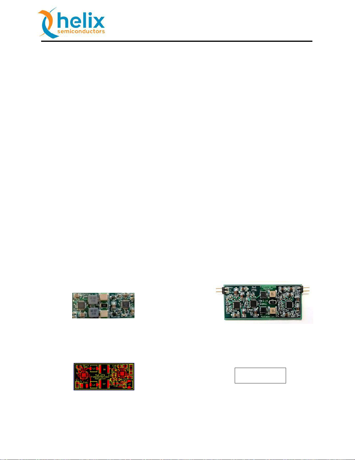
MxC™ 200 Evaluation Boards
Helix Semiconductors offers three MxC 200
DC-DC TL (Transformerless Isolation)
Evaluation Board configurations: 10W 48V
to isolated unregulated 12V output, 5W 5V
to isolated unregulated 5V output and 5W
48V to isolated unregulated ±12V and
regulated 5V output. Each evaluation board
is self-contained and ready for use.
Wiring connection diagram, schematic and
BOM for each board are included in this
manual. Gerber files are available upon
request.
Target Applications
PoE: Wireless Access Points, Security
Cameras, VoIP Phones
Electric & Hybrid Automobiles
Industrial Controllers, HVAC
Industry 4.0 Peripherals
IoT & IIoT Gateways
Features
Three Isolated Configurations
o 10W 48V to 12V Output
o 5W 5V to 5V Output
o 5W 48V to ±12V/5Vreg
Outputs
90% Efficiency @ 5W
85% Efficiency @ 10W
Highest Power Density
Low profile board module
All SMD manufacture
Adjustable On-Board Oscillator
Fault Detectors
o Output Over-Current
o Thermal Shutdown
External Control Signals
o Enable
o External Clock Enable
o External Clock Input
Helix Semiconductors, 2018 All Rights Reserved 1
Page 2

11.5.18
MxC™ 200 TL EVB Manual
1. Table of Contents
1. Table of Contents..................................................................................................................... 2
2. Table of Figures ....................................................................................................................... 2
3. Table of Tables ......................................................................................................................... 3
4. MxC 270 48V to 12V Output TL EVB ........................................................................................ 4
5. MxC 271 5V to 5V Output TL EVB ............................................................................................ 9
6. MxC 273 48V to ±12V & +5V Buck Reg. Output EVB ............................................................. 14
9. Output Current Sharing ......................................................................................................... 20
10. Performance Data .................................................................................................................. 21
10.1. Operational Guidelines .................................................................................................. 21
11. Flying Capacitor Value Verses Efficiency ............................................................................... 22
2. Table of Figures
Figure 1: MxC 270 48V to 12V Output TL EVB Block Diagram ........................................................ 4
Figure 2: MxC 270 48V to 12V Output TL EVB Standalone Wiring Diagram................................... 4
Figure 3: MxC 270 48V to 12V Output TL EVB Test Wiring Diagram .............................................. 5
Figure 4: MxC 270 48V to 12V Output TL EVB Schematic .............................................................. 6
Figure 5: MxC 270 48V to 12V Output TL EVB Efficiency Curve .................................................... 8
Figure 6: MxC 271 5V to 5V Output TL EVB Block Diagram ............................................................ 9
Figure 7: MxC 271 5V to 5V Output TL EVB Standalone Wiring Diagram ....................................... 9
Figure 8: MxC 271 5V to 5V Output TL EVB Test Wiring Diagram ................................................ 10
Figure 9: MxC 271 5V to 5V Output TL Output EVB Schematic .................................................... 11
Figure 10: MxC 271 5V to 5V Output TL Output EVB Efficiency Curve ......................................... 13
Figure 11: MxC 273 48V to ±12V & +5Vreg. Output TL EVB Block Diagram ................................. 14
Figure 12: MxC 273 48V to ±12V & +5Vreg. Output TL EVB Standalone Wiring Diagram ........... 14
Figure 13: MxC 273 48V to ±12V & +5Vreg. Output TL EVB Test Wiring Diagram ....................... 15
Figure 14: MxC 273 48V to ±12V & +5Vreg. Output TL EVB Schematic ....................................... 19
Figure 15: MxC 273 48V to ±12V & +5Vreg. Output TL EVB Efficiency Curve .............................. 19
Figure 16: MxC 270 Output Current Sharing 20W 48V-to12V TL EVB .......................................... 21
Figure 17: Efficiency Measurement Wiring Diagram .................................................................... 22
Figure 18: Typical Capacitance verses DC Bias, 50V Device ......................................................... 23
Helix Semiconductors, 2018 All Rights Reserved 2
Page 3

11.5.18
MxC™ 200 TL EVB Manual
3. Table of Tables
Table 1: MxC 270 48V to 12V Output TL EVB Connector – J1 and J2 ............................................. 5
Table 2: MxC 270 48V to 12V Output TL EVB Bill of Materials (BOM) ........................................... 7
Table 3: MxC 271 5V to 5V Output TL EVB Connector – J1 and J2 ............................................... 10
Table 4: MxC 271 5V to 5V Output TL EVB Bill of Materials (BOM) ............................................. 12
Table 5: MxC 273 48V to ±12V & +5Vreg. Output TL EVB Connector – J1 and J2 ........................ 15
Table 6: MxC 273 48V to ±12V & +5Vreg. Output TL EVB Bill of Materials (BOM) ...................... 17
Table 7: Revision History ............................................................................................................... 23
Helix Semiconductors, 2018 All Rights Reserved 3
Page 4
11.5.18
MxC™ 200 TL EVB Manual
4. MxC 270 48V to 12V Output TL EVB
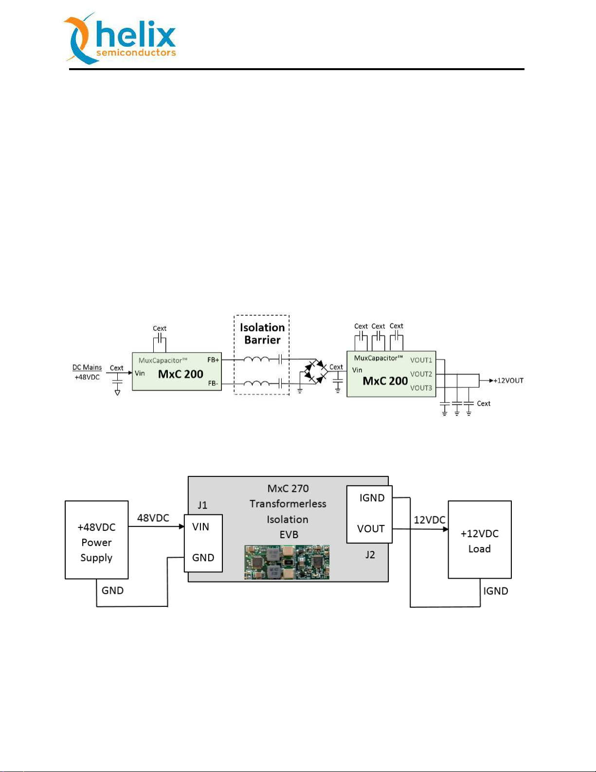
The MxC 270C-EB-1 48V to 12V Output TL (Transformer less Isolation) EVB is a standalone
isolated Divide-By-4 voltage reducer (Figure 2). The EVB is configured for 10W operation. A 4W
configuration is provided (see Figure 4) using cheaper, smaller components.
Isolation is provided via the isolation barrier capacitors. Different types of capacitors are to be
used depending on the required equipment safety classification. The 1.5KV capacitors used for
10W operation are not Y1/Y2 safety rated. Safety rated film capacitors can be substituted as
required. The 4W TL EVB configuration references Y2 safety rated MLCC capacitors.
The MxC 270 48V to 12V Output TL EVB provides the highest power density for an isolated 12V
output configuration. Additionally, a low-profile module can be manufactured using all SMD
components.
Figure 1: MxC 270 48V to 12V Output TL EVB Block Diagram
Figure 2: MxC 270 48V to 12V Output TL EVB Standalone Wiring Diagram
Helix Semiconductors, 2018 All Rights Reserved 4
Page 5
11.5.18
MxC™ 200 TL EVB Manual
Pin No.
Name
Description
J1-1
VIN
+48VDC Input Power Pin
J1-2
GND
Power GND Pin
J2-1
IVOUT
Isolated unregulated +12VDC Output Power Pin
J2-2
IGND
Isolated Power GND Pin
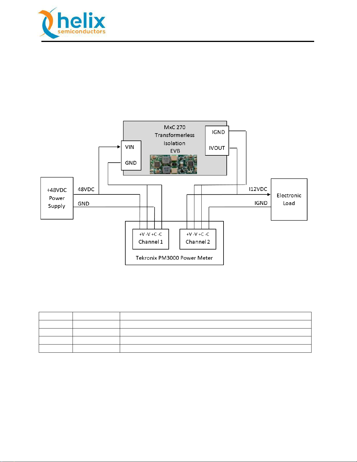
Warning: Do not “Hot-Plug” the power supply or electronic load.
Recommended start-up procedure:
1) With power supply turned off, attach power supply wires.
2) With electronic load disabled (monitor mode), attach electronic load wires.
3) Turn on power supply.
4) Enable electronic load with no load current, and then ramp up load current.
Note:
Figure 3: MxC 270 48V to 12V Output TL EVB Test Wiring Diagram
Table 1: MxC 270 48V to 12V Output TL EVB Connectors – J1 and J2
1) Due to board’s small size, thermal dissipation is limited and may exceed the over-
temperature shutdown threshold.
2) The MxC 270 can be powered from 24V delivering 6Vout.
Helix Semiconductors, 2018 All Rights Reserved 5
Page 6
11.5.18
MxC™ 200 TL EVB Manual
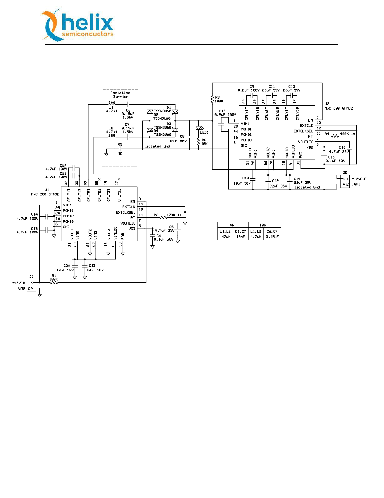
Figure 4: MxC 270 48V to 12V Output TL EVB Schematic
Helix Semiconductors, 2018 All Rights Reserved 6
Page 7
11.5.18
MxC™ 200 TL EVB Manual
Qty
Ref. No.
Description
Package
Manufacturer
2
C4, C15
CAP, 0.1µF±10%, 50V
0603
1608 Metric
Wurth Elektronik
WCAP-CSGP 885012206095
2
C5, C16
CAP, 4.7µF±10%, 35V
0603
1608 Metric
TDK
C1608X5R1V475M080AC
4
C3A, C3B,
C8, C10
CAP, 10µF±10%, 50V
1210
3225 Metric
TDK
C3225X7S1H106M250AB
4
C11, C12,
C13, C14
CAP, 22µF±10%, 35V
1206
3216 Metric
TDK
C3216X5R1V226M160AC
2
C9, C17
CAP, 0.22µF±10%, 100V
0805
2012 Metric
TDK
C2012X7S2A224K085AE
4
C1A, C1B,
C2A, C2B
CAP, 4.7µF±10%, 100V
1210
3225 Metric
TDK
C3225X7S2A475M200AB
1
R6
RES, 10KΩ±10%
0603
1608 Metric
Rohm
ESR03EZPJ103
2
R1, R3
RES, 100KΩ±10%
0603
1608 Metric
Rohm
ESR03EZPJ104
1
R2
RES, 178KΩ±1%
0603
1608 Metric
Rohm
MCR03ERTF1783
1
R4
RES, 402KΩ±1%
0603
1608 Metric
Rohm
MCR03ERTF4023
1
R5
NC
4
D1, D2,
D3, D4
DIODE, SCHOTTKY
SOD-123W
Taiwan Semiconductor
TSSW3U60
1
LED1
LED, Blue
0603
1608 Metric
Visual Communications
VAOL-S6SB4
2
U1, U2
IC, MxC 200, QFN5x5, 32P 0.5
QFN32
Helix Semiconductors
MxC 200C-QFN32-1
2
J1,J2
CONN, 2P, M, R/A, 0.100
SIP100P2
Wurth Elektronik
WR-PHD 61300211021
2
L1, L2
IND, 4.7uH
7.3mm x
6.60mm
Wurth Electronik
WE-LHMI 74437346047
2
C6, C7
CAP, 0.15uF, 1.5KV
2220
5750 Metric
Knowles Syfer
2220Y150154KXTWS2
Table 2: MxC 270 48V to 12V Output TL EVB Bill of Materials (BOM)
Helix Semiconductors, 2018 All Rights Reserved 7
Page 8

11.5.18
MxC™ 200 TL EVB Manual
Figure 5: MxC 270 48V to 12V Output TL EVB Efficiency Curve
Helix Semiconductors, 2018 All Rights Reserved 8
Page 9
11.5.18
MxC™ 200 TL EVB Manual
5. MxC 271 5V to 5V Output TL EVB
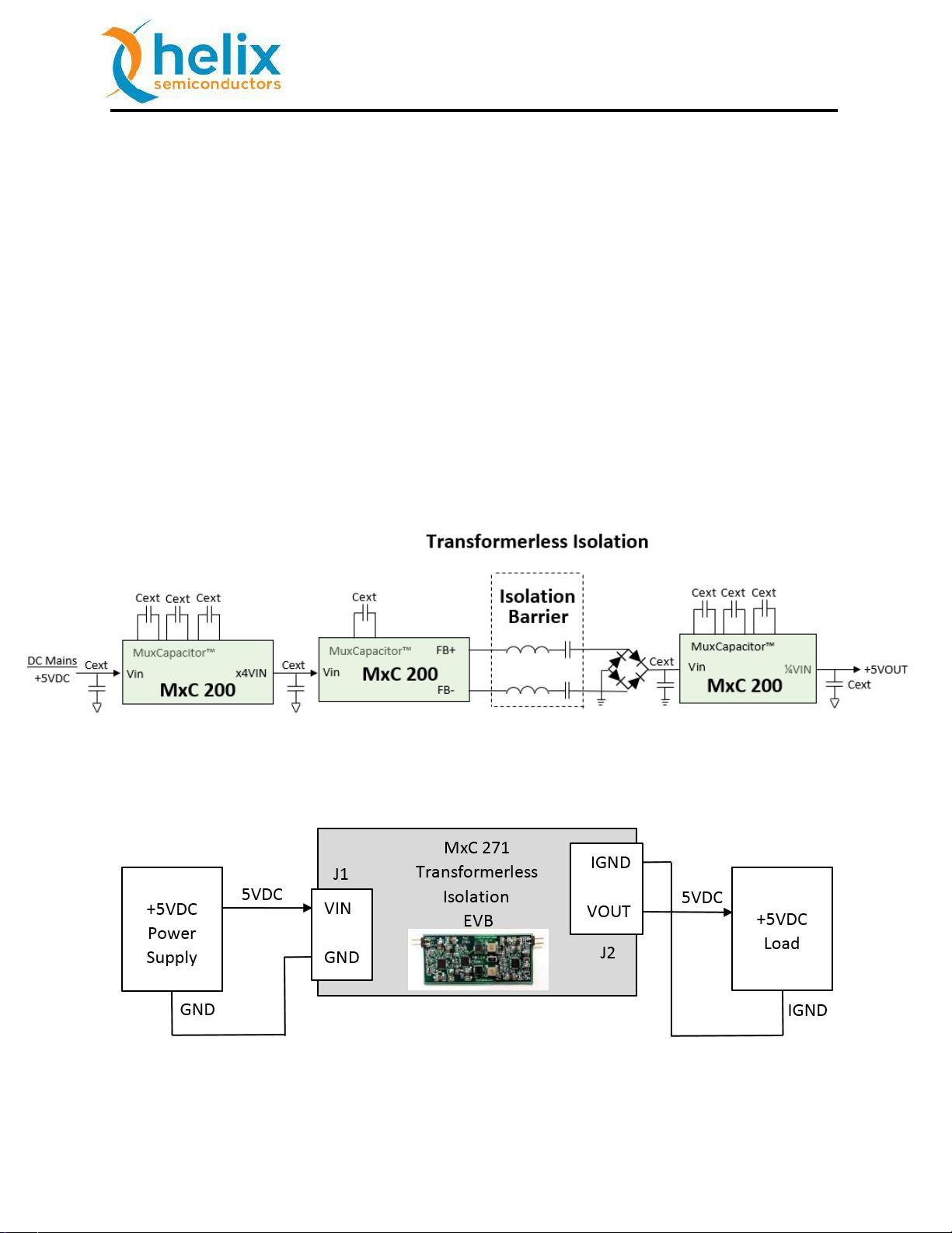
The MxC 271C-EB-1 5V to unregulated 5V Output TL (Transformer less Isolation) EVB is a
standalone isolated unity gain power interface (Figure 7). The EVB is configured for 5W
operation.
Isolation is provided via the isolation barrier capacitors. Different types of capacitors are to be
used depending on the required equipment safety classification. The 1.5KV capacitors used for
5W operation are not Y1/Y2 safety rated. Safety rated film capacitors can be substituted as
required.
The MxC 273 5V to unregulated 5V Output TL EVB provides the highest power density for a
non-transformer based isolated 5V output configuration. Additionally, a low-profile module
can be manufactured using all SMD components.
Figure 6: MxC 271 5V to 5V Output TL EVB Block Diagram
Figure 7: MxC 271 5V to 5V Output TL EVB Standalone Wiring Diagram
Warning: Do not “Hot-Plug” the power supply or electronic load.
Helix Semiconductors, 2018 All Rights Reserved 9
Page 10

11.5.18
MxC™ 200 TL EVB Manual
Pin No.
Name
Description
J1-1
VIN
+5VDC Input Power Pin
J1-2
GND
Power GND Pin
J2-1
IVOUT
Isolated unregulated +5VDC Output Power Pin
J2-2
IGND
Isolated Power GND Pin
Recommended start-up procedure:
1) With power supply off, attach power supply wires.
2) With electronic load disabled (monitor mode), attach electronic load wires.
3) Turn on power supply.
4) Enable electronic load with no load current, and then ramp up load current.
Note:
Figure 8: MxC 271 5V to 5V Output TL EVB Test Wiring Diagram
Table 3: MxC 271 5V to 5V Output TL EVB Connectors – J1 and J2
1) Due to board’s small size, thermal dissipation is limited and may exceed the over-
temperature shutdown threshold.
Helix Semiconductors, 2018 All Rights Reserved 10
Page 11
11.5.18
MxC™ 200 TL EVB Manual
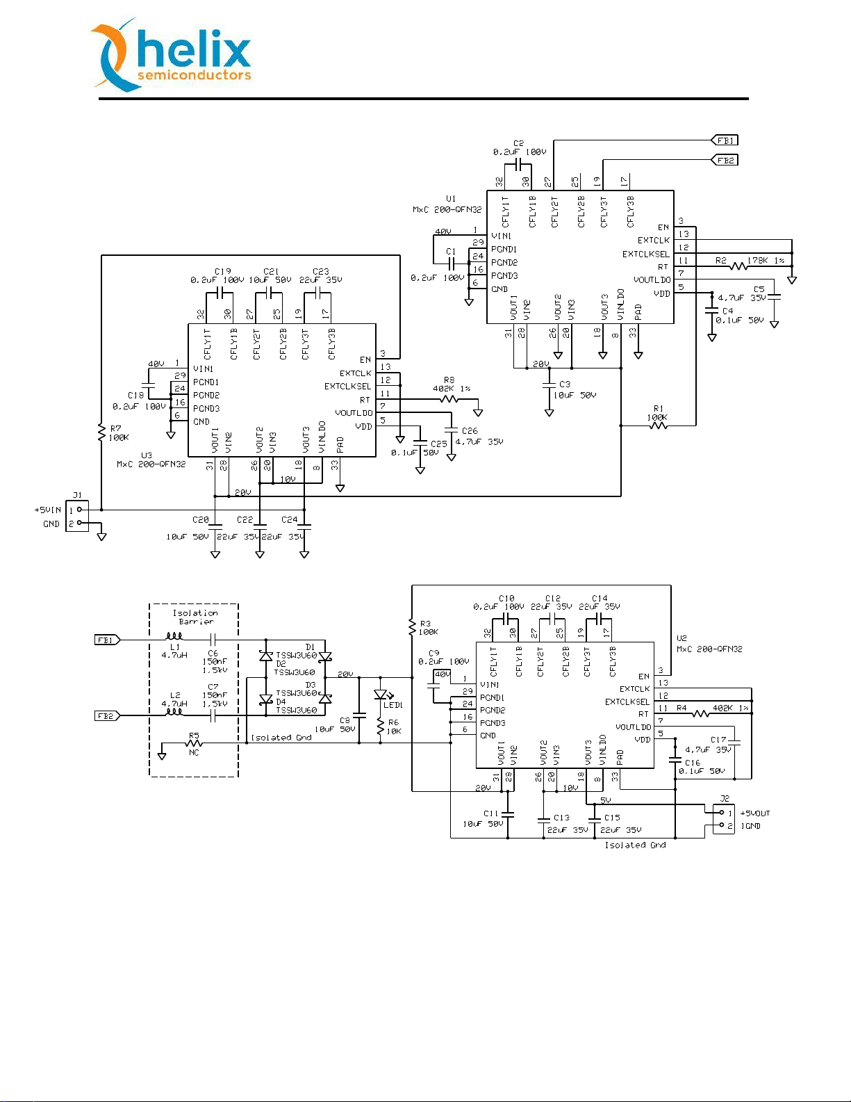
Figure 9: MxC 271 5V to 5V Output TL EVB Schematic
Helix Semiconductors, 2018 All Rights Reserved 11
Page 12

11.5.18
MxC™ 200 TL EVB Manual
Qty
Ref. No.
Description
Package
Manufacturer
3
C4, C16,
C25
CAP, 0.1µF±10%, 50V
0603
1608 Metric
Wurth Elektronik
WCAP-CSGP 885012206095
3
C5, C17,
C26
CAP, 4.7µF±10%, 35V
0603
1608 Metric
TDK
C1608X5R1V475M080AC
5
C3A, C3B,
C8, C11,
C20, C21
CAP, 10µF±10%, 50V
1210
3225 Metric
TDK
C3225X7S1H106M250AB
7
C12, C13,
C14, C15,
C22, C23,
C24
CAP, 22µF±10%, 35V
1206
3216 Metric
TDK
C3216X5R1V226M160AC
6
C1, C2, C9,
C10, C18,
C19
CAP, 0.22µF±10%, 100V
0805
2012 Metric
TDK
C2012X7S2A224K085AE
1
R6
RES, 10KΩ±10%
0603
1608 Metric
Rohm
ESR03EZPJ103
3
R1, R3, R7
RES, 100KΩ±10%
0603
1608 Metric
Rohm
ESR03EZPJ104
1
R2
RES, 178KΩ±1%
0603
1608 Metric
Rohm
MCR03ERTF1783
2
R4, R8
RES, 402KΩ±1%
0603
1608 Metric
Rohm
MCR03ERTF4023
1
R5
RES, 10MΩ±10%
2512
6432 Metric
Stackpole
RMCF2512JT10M0
4
D1, D2,
D3, D4
DIODE, SCHOTTKY
SOD-123W
Taiwan Semiconductor
TSSW3U60
1
LED1
LED, Blue
0603
1608 Metric
Visual Communications
VAOL-S6SB4
3
U1, U2,
U3
IC, MxC 200, QFN5x5, 32P 0.5
QFN32
Helix Semiconductors
MxC 200C-QFN32-1
2
J1,J2
CONN, 2P, M, R/A, 0.100
SIP100P2
Wurth Elektronik
WR-PHD 61300211021
2
L1, L2
IND, 4.7uH
7.3mm x
6.60mm
Wurth Electronik
WE-LHMI 74437346047
2
C6, C7
CAP, 0.15uF, 1.5KV
2220
5750 Metric
Knowles Syfer
2220Y150154KXTWS2
Table 4: MxC 271 5V to 5V Output TL EVB Bill of Materials (BOM)
Helix Semiconductors, 2018 All Rights Reserved 12
Page 13

11.5.18
MxC™ 200 TL EVB Manual
Future Product
Figure 10: MxC 271 5V to 5V Output TL EVB Efficiency Curve
Helix Semiconductors, 2018 All Rights Reserved 13
Page 14

11.5.18
MxC™ 200 TL EVB Manual
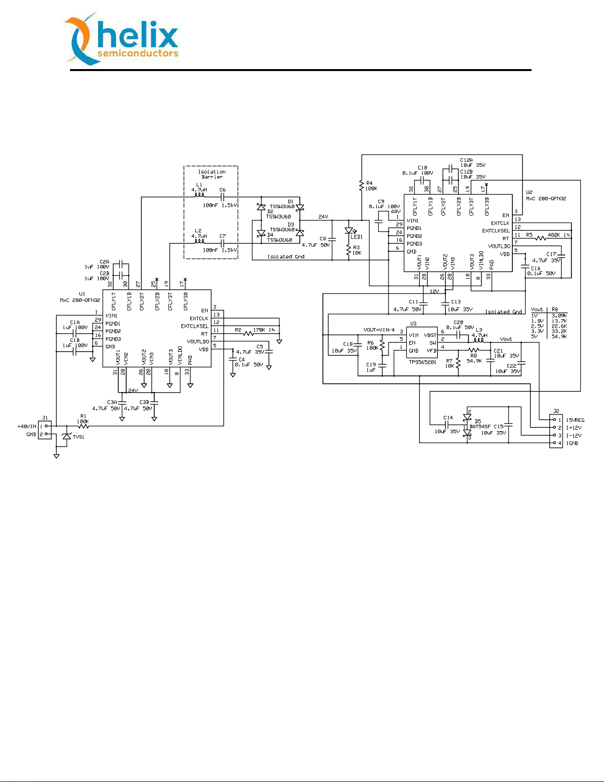
6. MxC 273 48V to ±12V & +5V Buck Reg. Output EVB
The MxC 273C-EB-1 48V to unregulated ±12V & regulated +5V Output TL (Transformer less
Isolation) EVB is a standalone isolated Divide-By-4 voltage reducer with a PoL regulator (Figure
12). The EVB is configured for 5W operation. The PoL regulator can be added to the MxC 270
for a 10W power configuration.
Isolation is provided via the isolation barrier capacitors. Different types of capacitors are to be
used depending on the required equipment safety classification. The 1.5KV capacitors used for
5W operation are not Y1/Y2 safety rated. Safety rated film capacitors can be substituted as
required.
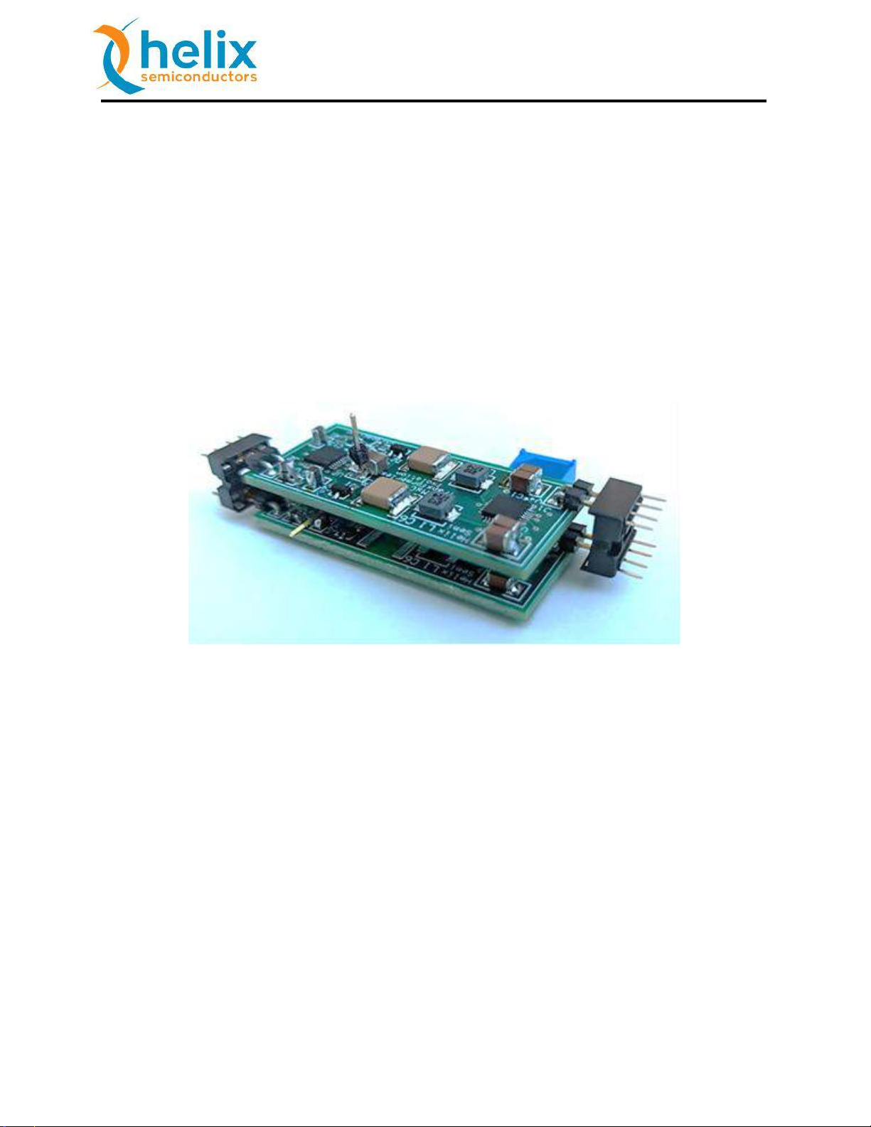
The MxC 273 48V to ±12V & regulated +5V Output TL EVB provides the highest power density
for an isolated multi-output 12V & 5V configuration. Additionally, a low-profile module can be
manufactured using all SMD components.
Figure 11: MxC 273 48V to ±12V & +5Vreg Output TL EVB Block Diagram
Figure 12: MxC 273 48V to ±12V & +5Vreg Output TL EVB Standalone Wiring Diagram
Helix Semiconductors, 2018 All Rights Reserved 14
Page 15
11.5.18
MxC™ 200 TL EVB Manual
Pin No.
Name
Description
J1-1
VIN
+5VDC Input Power Pin
J1-2
GND
Power GND Pin
J2-1
I5VREG
Isolated regulated +5VDC Output Power Pin
J2-2
I+12V
Isolated unregulated +12VDC Output Power Pin
J2-3
I-12V
Isolated unregulated -12VDC Output Power Pin
J2-4
IGND
Isolated Power GND Pin
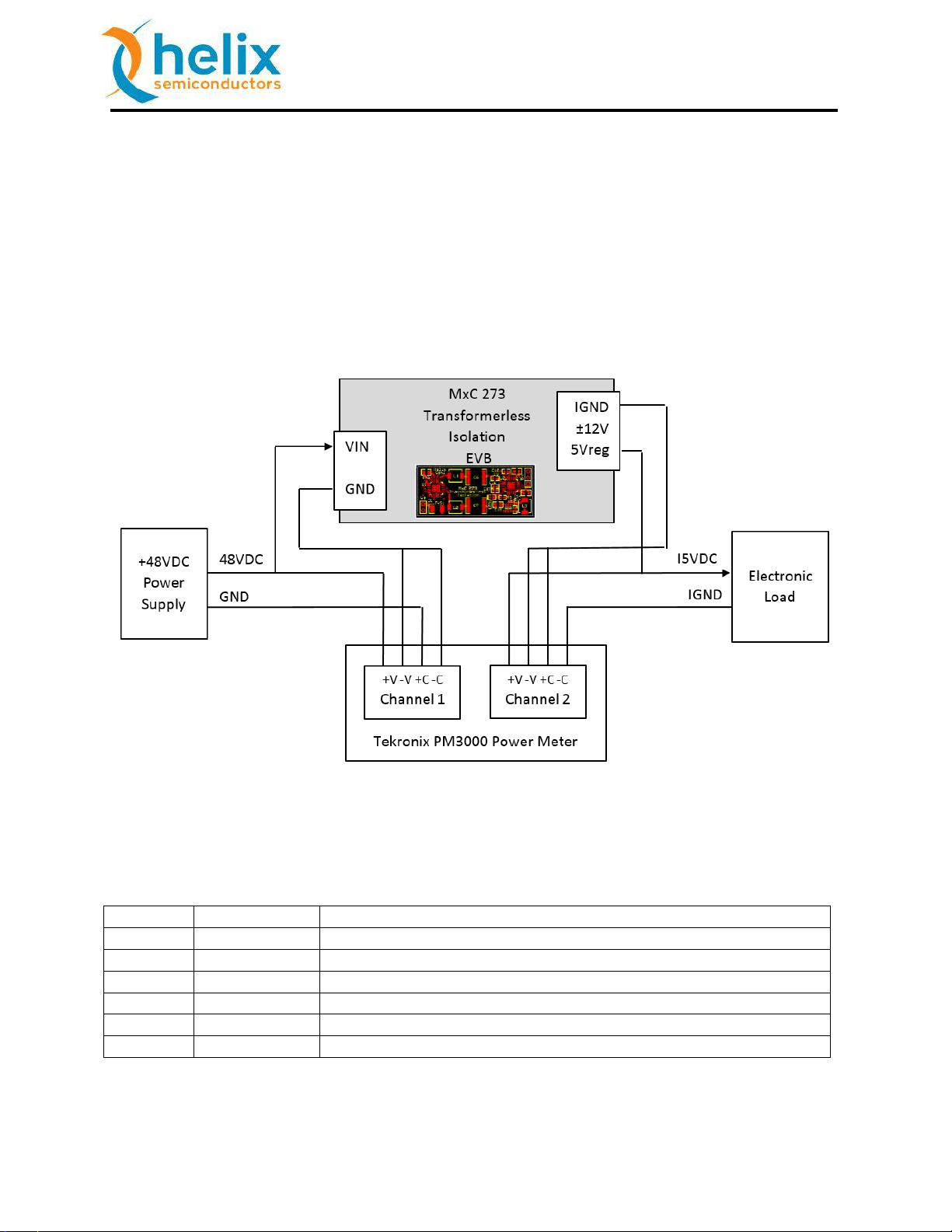
Warning: Do not “Hot-Plug” the power supply or electronic load.
Recommended start-up procedure:
1) With power supply off, attach power supply wires.
2) With electronic load disabled (monitor mode), attach electronic load wires.
3) Turn on power supply.
4) Enable electronic load with no load current, and then ramp up load current.
Figure 13: MxC 273 48V to ±12V & +5Vreg Output TL EVB Test Wiring Diagram
Table 5: MxC 273 48V to ±12V & +5Vreg Output TL EVB Connectors – J1 and J2
Helix Semiconductors, 2018 All Rights Reserved 15
Page 16

11.5.18
MxC™ 200 TL EVB Manual
Note:
1) Due to board’s small size, thermal dissipation is limited and may exceed the over-
temperature shutdown threshold.
2) The MxC 200 can be powered from 24V delivering 6V to the buck regulator at reduced
output power. The minimum VIN for the TPS565201 is 4.5V.
3) Other buck regulator output voltages are available by changing R8. Refer to the VOUT
Table in Figure 14 schematic.
Helix Semiconductors, 2018 All Rights Reserved 16
Page 17
11.5.18
MxC™ 200 TL EVB Manual
Qty
Ref. No.
Description
Package
Manufacturer
3
C4, C16, c20
CAP, 0.1µF±10%, 50V
0603
1608 Metric
Wurth Elektronik
WCAP-CSGP 885012206095
2
C5, C17
CAP, 4.7µF±10%, 35V
0603
1608 Metric
TDK
C1608X5R1V475M080AC
5
C3A, C3B,
C8, C11, C18
CAP, 4.7µF±10%, 50V
0805
2012 Metric
SAMSUNG
CL21A4475KBQNNNE
5
C12A, C12B,
C13, C14,
C15
CAP, 10µF±10%, 35V
0805
2012 Metric
MURATA
GRM21BCBYA106KE11L
2
C9, C10
CAP, 0.1µF±10%, 100V
0805
2012 Metric
TDK
C2012X7S2A104K085AE
4
C1A, C1B,
C2A, C2B
CAP, 1µF±10%, 100V
0805
2012 Metric
TDK
C2012X7S2A105K125AE
1
R3
RES, 10KΩ±10%
0603
1608 Metric
Rohm
ESR03EZPJ103
3
R1, R4, R6
RES, 100KΩ±10%
0603
1608 Metric
Rohm
ESR03EZPJ104
1
R2
RES, 178KΩ±1%
0603
1608 Metric
Rohm
MCR03ERTF1783
1
R5
RES, 402KΩ±1%
0603
1608 Metric
Rohm
MCR03ERTF4023
4
D1, D2, D3,
D4
DIODE, SCHOTTKY, 60V, 3A
SOD-123W
Taiwan Semiconductor
TSSW3U60
2
U1, U2
IC, MxC 200, QFN5x5, 32P 0.5
QFN32
Helix Semiconductors
MxC 200C-QFN32-1
1
J1
CONN, 2P, M, R/A, 0.100
SIP100P2
Wurth Elektronik
WR-PHD 61300211021
1
J2
CONN, 4P, M, R/A, 0.100
SIP100P4
Wurth Elektronik
WR-PHD 61300411021
3
L1, L2, L3
IND, 4.7uH, 2.2A
4.45mm x
4.06mm
Wurth Electronik
WE-LHMI 74437324047
2
C6, C7
CAP, 0.1uF, 1.5KV
2220
5750 Metric
AVX
2220AC104KAT1A
1
C19
CAP, 1µF±10%, 16V
0603
1608 Metric
Wurth Elektronik
WCAP-CSGP 885012106017
1
R8
RES, 54.9KΩ±1%
0603
1608 Metric
Rohm
MCR03ERTF5493
1
R7
RES, 10.0KΩ±1%
0603
1608 Metric
Rohm
MCR03ERTF1003
1
U2
IC, TPS565201
TSOP8
TI
TPS565201D
1
D5
DIODE, SCHOTTKY, DUAL
SOT23
ST Microelectronics
BAT54SFFILMY
Table 6: MxC 273 48V to ±12V & +5Vreg Output TL EVB Bill of Materials (BOM)
Helix Semiconductors, 2018 All Rights Reserved 17
Page 18
11.5.18
MxC™ 200 TL EVB Manual
Formatting problem from reducing font in table 6 to get it on 1 page. If this line is removed,
there is a blank page instead.
Figure 14: MxC 273 48V to ±12V & +5Vreg Output TL EVB Schematic
Helix Semiconductors, 2018 All Rights Reserved 18
Page 19

11.5.18
MxC™ 200 TL EVB Manual
Future Product
Figure 15: MxC 273 48V to ±12V & +5Vreg Output TL EVB Efficiency Curve
Helix Semiconductors, 2018 All Rights Reserved 19
Page 20
11.5.18
MxC™ 200 TL EVB Manual
9. Output Current Sharing
The MxC 200 MuxCapacitor outputs can be wire-OR’ed for higher output current capacity. No
special synchronization is required. The following example uses the Single 12V Output MxC 270
EVB. Each individual MxC 200 cell can be connected in parallel with adjacent cells: All the VIN1 pins
are connected together. Similarly, all respective GND pins, VOUT2, and VOUT3 pins can be
connected together.. The VOUT2 and VOUT3 outputs of MxC 200 are connected in parallel for
maximum efficiency.
Figure 16: MxC 270 Output Current Sharing 20W 48V-to-12V TL EVM
Helix Semiconductors, 2018 All Rights Reserved 20
Page 21
11.5.18
MxC™ 200 TL EVB Manual
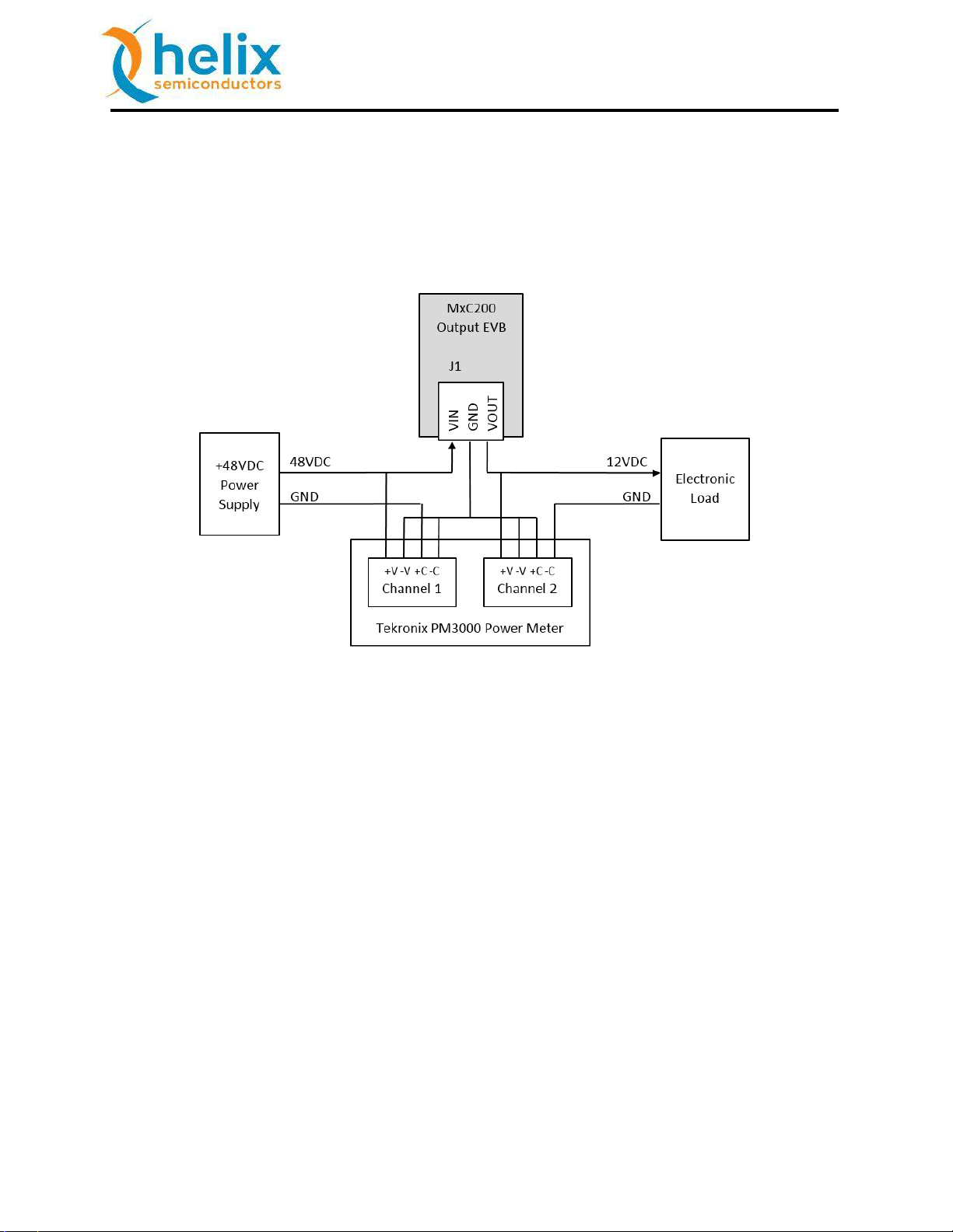
10. Performance Data
The previous MuxCapacitor efficiency data was measured using a Tektronix PM3000 power meter.
The figure below shows the test equipment wiring diagram.
Figure 17: Efficiency Measurement Wiring Diagram
10.1. Operational Guidelines
It is recommended that the auto-ranging feature of current meters be disabled when performing
efficiency measurements. The MxC 200 over current detector can trip when the current meter
switches between ranges.
The startup waveform of VIN must be monotonic.
Depending on the startup load and VIN rise time, the startup over current detector can trip. A high
startup load condition plus distributed filter capacitance could cause an over-current shutdown.
Helix Semiconductors, 2018 All Rights Reserved 21
Page 22
11.5.18
MxC™ 200 TL EVB Manual
11. Flying Capacitor Value Verses Efficiency
The MxC 200 flying capacitors can be reduced in value for lower output power applications. Lower
cost, smaller package size, etc. are tradeoffs that can affect the efficiency performance.
The Flying Capacitor’s value is critical to the maximum load operating performance of the
MuxCapacitor. If the flying capacitance is too small the efficiency of the MuxCapacitor decreases.
Too little capacitance for the required output current effectively behaves as an increase in the
impedance of the MuxCapacitor cell.
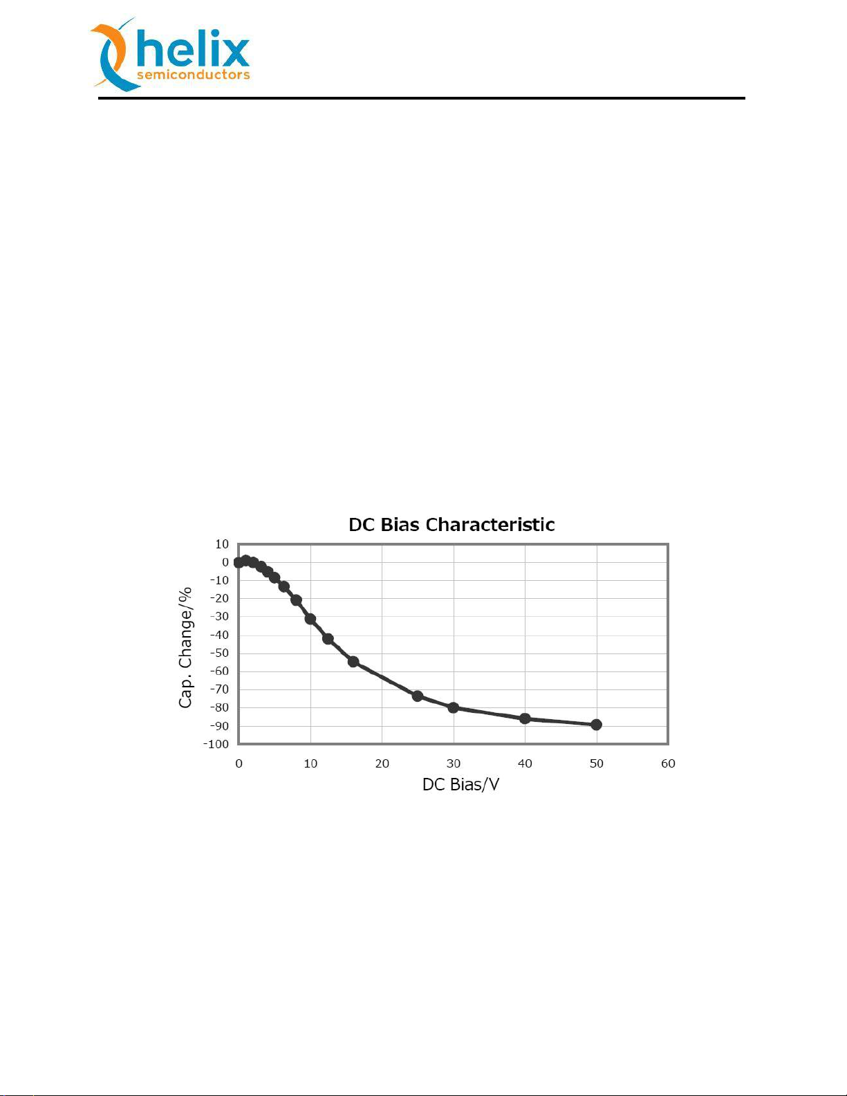
The effective operating capacitance of ceramic capacitors are subject to a DC Bias derating. As the
DC voltage across the capacitor increases, the capacitor’s capacitance value decreases. This DC Bias
effect must be considered when operating the capacitor too close to its maximum rated voltage or
selecting smaller case sizes.
There are other trade-offs that must be analyzed for reliable, efficient and safe capacitor operation.
Figure 18: Typical Capacitance verses DC Bias, 50V Device
Helix Semiconductors, 2018 All Rights Reserved 22
Page 23

11.5.18
MxC™ 200 TL EVB Manual
Operational Headquarters
9980 Irvine Center Drive
Suite 100
Irvine, CA 92618
Information & Sales
949-748-6057
sales@helixsemiconductors.com
Technical Support
949-748-7026
support@helixsemiconductors.com
Engineering & Design Office
5475 Mark Dabling Blvd.
Suite 206
Colorado Springs, CO 80918
719-594-7098
designs@helixsemiconductors.com
Corporate Headquarters
4808 West Utica Ave.
Broken Arrow, OK 74011
Date
Revision
Description
11.5.18
1
Initial Release
Table 7: Revision History
Helix Semiconductors, 2018 All Rights Reserved 23
 Loading...