

Page 1
deutsch / english
M SIX
6-Kanal Verstärker mit integrierter aktiver
Frequenzweiche
6-channel amplier with integrated active
crossover
Page 2

Herzlichen Glückwunsch!
Sehr geehrter Kunde,
Wir gratulieren Ihnen zum Kauf dieses hochwertigen HELIX Verstärkers.
Audiotec Fischer setzt mit der HELIX M SIX neue
Maßstäbe im Bereich der Verstärkertechnik.
Dabei protieren Sie als Kunde direkt von unserer
mehr als 30-jährigen Erfahrung in der Forschung
und Entwicklung von Audiokomponenten.
Allgemeine Hinweise
Allgemeines zum Einbau von HELIX-Komponenten
Um alle Möglichkeiten des Produktes optimal ausschöpfen zu können, lesen Sie bitte sorgfältig die
nachfolgenden Installationshinweise. Wir garantieren, dass jedes Gerät vor Versand auf seinen einwandfreien Zustand überprüft wurde.
Vor Beginn der Installation unterbrechen Sie
den Minusanschluss der Autobatterie.
Wir empfehlen Ihnen, die Installation von einem
Einbauspezialisten vornehmen zu lassen, da der
Nachweis eines fachgerechten Einbaus und Anschlusses des Gerätes Voraussetzung für die Garantieleistungen sind.
Dieser Verstärker wurde von uns nach neuesten
technischen Erkenntnissen entwickelt und zeichnet
sich durch hervorragende Verarbeitung und eine
überzeugende Anwendung ausgereifter Technologien aus.
Viel Freude an diesem Produkt wünscht Ihnen das
Team von
AUDIOTEC FISCHER
sind. Diese könnten sonst beschädigt werden. Achten Sie bitte darauf, dass sich solche Teile auch in
der doppelten Wandverkleidung verbergen können.
Allgemeines zum Anschluss des M SIX Verstärkers
Der Verstärker darf nur in Kraftfahrzeuge eingebaut
werden, die den 12 V-Minuspol an Masse haben.
Bei anderen Systemen können der HELIX Verstärker und die elektrische Anlage des Kfz beschädigt
werden. Die Plusleitung für die gesamte Anlage
sollte in einem Abstand von max. 30 cm von der
Batterie mit einer Hauptsicherung abgesichert werden. Der Wert der Sicherung errechnet sich aus der
maximalen Stromaufnahme der Car-Hi Anlage.
Installieren Sie Ihren Verstärker an einer trocke-
nen Stelle im Auto und vergewissern Sie sich, dass
der Verstärker am Montageort genügend Kühlung
erhält. Montieren Sie das Gerät nicht in zu kleine,
abgeschlossene Gehäuse ohne Luftzirkulation
oder in der Nähe von wärmeabstrahlenden Teilen
oder elektronischen Steuerungen des Fahrzeuges.
Im Sinne der Unfallsicherheit muss der Verstärker
professionell befestigt werden. Dieses geschieht
über Schrauben, die in eine Montageäche eingeschraubt werden, die wiederum genügend Halt
bieten muss.
Bevor Sie die Schrauben im Montagefeld befestigen, vergewissern Sie sich, dass keine elektrischen
Kabel und Komponenten, hydraulische Bremslei-
tungen, der Benzintank etc. dahinter verborgen
2
Verwenden Sie zum Anschluss des Verstärkers
an die Stromversorgung des Fahrzeugs ausschließlich geeignete Kabel mit ausreichendem Kabelquerschnitt. Die Sicherungen im
Verstärker dürfen nur mit den gleichen Werten
(2 x 35 A) ersetzt werden, um eine Beschädigung des Gerätes zu verhindern. Höhere Werte
können zu gefährlichen Folgeschäden führen!
Die Kabelverbindungen müssen so verlegt sein,
dass keine Klemm-, Quetsch- oder Bruchgefahr besteht. Bei scharfen Kanten (Blechdurchführungen)
müssen alle Kabel gegen Durchscheuern gepolstert sein. Ferner darf das Versorgungskabel niemals
mit Zuleitungen zu Vorrichtungen des Kfz (Lüftermotoren, Brandkontrollmodulen, Benzinleitungen
etc.) verlegt werden.
Page 3
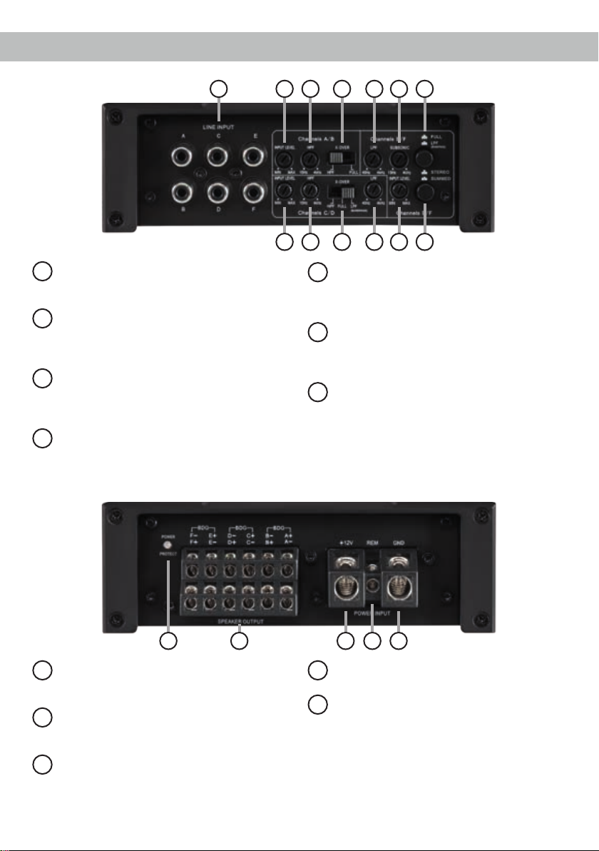
Anschluss- und Bedienelemente
1 2 53 4 6
Line Input
1
Cinch-Eingänge zum Anschluss eines
Vorverstärkersignals.
Input Level
2
Regler zum Einstellen der Eingangsemp-
ndlichkeit des Line Inputs für die einzelnen
Stereo-Kanäle.
HPF
3
Regler zum Einstellen des Hochpasslters
der Kanalpaare A/B und C/D von 15 Hz bis
4.000 Hz.
X-Over
4
Schalter zum Aktivieren der verschiedenen
Filter pro Kanalpaar.
4
3 4 5 22
LPF
5
Regler zum Einstellen des Tiefpasslters
der Kanalpaare C/D und E/F von 40 Hz bis
4.000 Hz.
Subsonic / HPF
6
Regler zum Einstellen des Subsoniclters /
Hochpasslters für das Kanalpaar E/F von
15 bis 4.000 Hz.
Input Mode Kanal E/F
7
Schalter zur Bildung eines Summensignals
aus den Eingangssignalen der Kanäle E und
F und dessen Verteilung auf die jeweiligen
Verstärkerkanäle.
7
9 10 11 128
Power & Protect LED
8
Die Power & Protect LED zeigt den
Betriebszustand des Verstärkers an.
Speaker Output
9
Lautsprecherausgänge für den Anschluss
von Lautsprechersystemen.
+12 V
10
Anschluss für das Versorgungsspannungs-
kabel +12 V der Batterie.
REM
11
Anschluss für die Remoteleitung.
GND
12
Anschluss des Massekabels (Minuspol der
Batterie oder Fahrzeugchassis).
3
Page 4
Inbetriebnahme und Funktionen
Line Input
1
6-Kanal Vorverstärkereingang zum Anschluss von
Signalquellen, wie z.B. Radios, die mit dem/den
Vorverstärkerausgang/-ausgängen bzw. Line Outputs der Signalquelle verbunden werden können.
Input Level
2
Mit Hilfe dieser Regler kann die Eingangsempndlichkeit der Kanalpaare A/B, C/D und E/F an die
Ausgangsspannung des angeschlossenen Radios
angepasst werden. Diese Regler sind keine Lautstärkeregler, sondern dienen nur der Anpassung.
Der Regelbereich liegt zwischen 0,5 - 6 Volt.
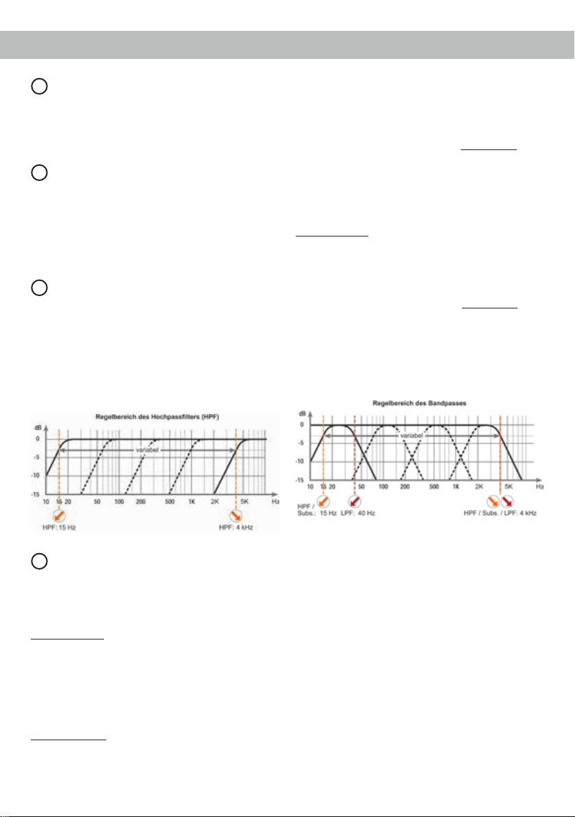
HPF
3
Mit Hilfe dieser Regler kann das Hochpasslter von
15 Hz bis 4.000 Hz für die Kanalpaare A/B und C/D
eingestellt werden.
Der Regler wird aktiviert, wenn der X-Over Schal-
ter auf HPF (Hochpasslter) eingestellt ist. Bei dem
Kanalpaar C/D ist dieser Regler auch in der X-Over
Schalterstellung LPF (Bandpass) aktiviert und
muss zwingend eingestellt werden.
Kanalpaares C/D die Übernahmefrequenz für den
Hochpass eingestellt werden. Bei Schalterstellung
FULL (Fullrange) ist die interne Frequenzweiche
nicht aktiv. Bei Schalterstellung LPF (Tiefpasslter /
Bandpass) ist das Hochpasslter immer aktiv. Das
heißt, es wird in jedem Fall ein Bandpass gebildet.
Mit dem Regler 3 wird der Hochpass und mit dem
Regler 5 des Kanalpaares C/D der Tiefpass eingestellt. So kann jeder beliebige Bandpass zwischen
15 Hz und 4.000 Hz eingestellt werden.
Kanalpaar E/F: Fullrange oder Tiefpasslter / Band-
pass.
Bei Schalterstellung FULL (Fullrange) ist die inter-
ne Frequenzweiche nicht aktiv. Wird dieser Schalter auf LPF (Tiefpasslter / Bandpass) gestellt, ist
der Subsoniclter / Hochpasslter immer aktiv. Das
heißt, es wird in jedem Fall ein Bandpass gebildet.
Mit dem Regler 6 wird der Subsoniclter / Hochpasslter und mit dem Regler 5 des Kanalpaares
E/F der Tiefpass eingestellt. So kann jeder beliebige Bandpass zwischen 15 Hz und 4.000 Hz eingestellt werden.
X-Over
4
Zur Umschaltung der internen, aktiven Frequenzweichen auf Hochpass, Fullrange oder Tiefpass
bzw. Bandpass. Die Auswahlmöglichkeiten variieren je nach Kanalpaar.
Kanalpaar A/B: Hochpasslter oder Fullrange.
Wird dieser X-Over Schalter auf HPF (Hochpass-
lter) gestellt, so kann mit Hilfe des Reglers 3 des
Kanalpaares A/B die Übernahmefrequenz für den
Hochpass eingestellt werden. Bei Schalterstellung
FULL (Fullrange) ist die interne Frequenzweiche
nicht aktiv.
Kanalpaar C/D: Hochpasslter, Fullrange oder Tiefpasslter / Bandpass.
Wird dieser X-Over Schalter auf HPF (Hochpass-
lter) gestellt, so kann mit Hilfe des Reglers 3 des
4
Achtung: Bitte vergewissern Sie sich, dass beim
Einstellen eines Bandpasses die Übernahme-
frequenzen von Hochpass bzw. Subsonic / HPF
und Tiefpass mindestens zwei Oktaven auseinander liegen, um einen Pegelverlust zu vermei-
den! Das heißt: Wird das Tiefpasssignal z.B. auf
320 Hz eingestellt, so sollte der Hochpass bzw.
Subsonic / HPF um mindestens zwei Oktaven tiefer
auf ca. 80 Hz eingestellt werden. (1 Oktave = Frequenzverdopplung oder Frequenzhalbierung).
Page 5
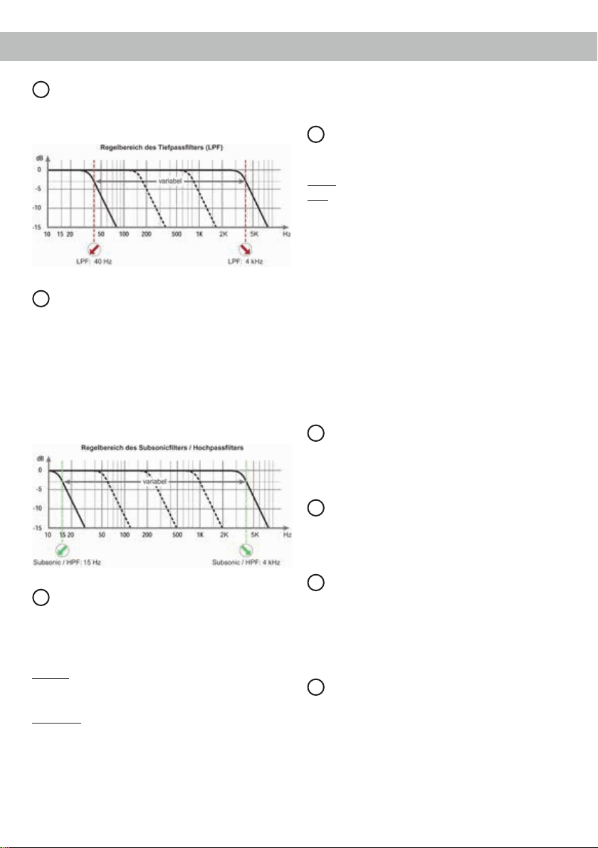
LPF
5
Mit Hilfe dieser Regler kann das Tiefpasslter von
40 Hz bis 4.000 Hz für die Kanalpaare C/D und E/F
eingestellt werden.
Subsonic / HPF
6
Mit Hilfe dieses Reglers kann der Subsoniclter /
Hochpasslter von 15 Hz bis 4.000 Hz für das Ka-
nalpaar E/F eingestellt werden. Dieses Filter dient
dazu, sehr tiefe Frequenzen außerhalb des Hör-
spektrums herauszultern und so den Subwoofer
und den Verstärker zu entlasten, um mehr Leistung
für die wahrnehmbaren Frequenzen zur Verfügung
zu haben. Dieser Regler ist immer aktiv und muss
zwingend eingestellt werden.
nommen werden, wenn Sie einen Basslautsprecher
an die Lautsprecherausgänge E und F anschließen.
Power & Protect LED
8
Die Power & Protect LED zeigt den Betriebszustand
des Verstärkers an.
Grün: Verstärker eingeschaltet und betriebsbereit.
Rot: Es besteht eine Fehlfunktion des Verstär-
kers. Diese Fehlfunktion kann unterschiedliche Ursachen haben, da die M SIX mit
verschiedenen elektronischen Schutzschaltungen ausgestattet ist. Diese schalten
den Verstärker bei Überhitzung, Über- und
Unterspannung, Kurzschluss am Lautsprecherausgang und Fehlanschluss ab. Prüfen
Sie in diesem Fall alle Anschlüsse auf Fehler, wie z.B. Kurzschlüsse, fehlerhafte Verbindungen oder Falscheinstellungen und
Übertemperatur. Sollte sich der Verstärker
nach Beseitigung der Fehlerquelle nicht
wieder einschalten lassen, liegt ein Defekt
vor.
Speaker Output
9
Diese Anschlüsse dienen als Lautsprecherausgänge. Die Impedanz der Lautsprecher darf 2 Ohm (im
Brückenbetrieb 4 Ohm) nicht unterschreiten.
Input Mode Kanal E/F
7
Dieser Schalter dient zur Bildung eines Summensignals aus den Eingangssignalen der Kanäle E und
F und dessen Verteilung auf die jeweiligen Verstärkerkanäle.
Stereo: Die Lautsprecherausgänge E und F werden
mit dem jeweiligen Eingangssignal der lowlevel Eingänge E und F versorgt.
Summed: Aus den Eingangssignalen E und F wird
ein Summensignal gebildet, d.h. an den Lautsprecherausgängen E und F wird das gleiche Signal
ausgegeben.
Hinweis: Zur Bildung eines Summensignals müssen beide Eingangskanäle (E und F) belegt werden.
Die Summierung der Eingangssignale sollte vorge-
10
+12 V
Das +12 V Versorgungskabel ist am Pluspol der
Batterie anzuschließen. Der empfohlene Querschnitt beträgt mindestens 10 mm².
11
REM
Die Remoteleitung wird mit dem Remote-Ausgang /
Antennenanschluss des Steuergerätes (Radio) verbunden. Dieser ist nur aktiviert, wenn das Steuerge-
rät eingeschaltet ist. Somit wird der Verstärker mit
dem Steuergerät ein- und ausgeschaltet.
12
GND
Das Massekabel sollte am zentralen Massepunkt
(dieser bendet sich dort wo der Minuspol der Batterie zum Metallchassis des Kfz geerdet ist) oder an
einer blanken, von Lackresten befreiten Stelle des
Kfz-Chassis angeschlossen werden. Der empfohlene Querschnitt beträgt mindestens 10 mm².
5
Page 6

Einbau und Installation
Die HELIX M SIX wird wie nachfolgend beschrieben an das Autoradio angeschlossen.
Achtung: Für die Durchführung der nachfolgenden
Schritte werden Spezialwerkzeuge und Fachwissen
benötigt. Um Anschlussfehler und Beschädigungen
zu vermeiden, fragen Sie im Zweifelsfall Ihren Einbauspezialisten und beachten Sie zwingend die
allgemeinen Anschluss- und Einbauhinweise (siehe
Seite 2).
1. Anschluss der Vorverstärkereingänge
Diese Eingänge (Line Input) können mit entsprechenden Kabeln (RCA / Cinch-Kabel) an
die Vorverstärker- / Lowlevel- / Cinch-Ausgänge des Radios angeschlossen werden.
2. Einstellung der Eingangsempndlichkeit
Achtung: Es ist zwingend notwendig die
Eingangsempndlichkeit der M SIX an die
Signalquelle anzupassen, um Schäden am
Verstärker zu vermeiden.
Um die Eingangsempndlichkeit je Kanalpaar
zu verändern, verwenden Sie die drei Drehreg-
ler (siehe Seite 4, Punkt 2; Input Level).
3. Anschluss der Stromversorgung
Vor dem Anschluss des +12 V Versorgungs-
kabels an das Bordnetz muss die Autobatterie abgeklemmt werden.
Das +12 V Stromkabel ist am Pluspol der Bat-
terie anzuschließen. Die Plusleitung sollte in
einem Abstand von max. 30 cm von der Batterie
mit einer Hauptsicherung abgesichert werden.
Der Wert der Sicherung errechnet sich aus der
maximalen Stromaufnahme der gesamten CarHi Anlage (M SIX = max. 70 A RMS bei 12 V
Bordnetz).
Verwenden Sie bei kurzen Leitungen (< 1 m)
einen Querschnitt von mindestens 10 mm². Bei
längeren Leitungen empfehlen wir einen Quer-
schnitt von 16 mm² bis 25 mm².
Das Massekabel (gleicher Querschnitt wie
das +12 V Kabel) muss an einem blanken,
von Lackresten befreiten Massepunkt des
Kfz-Chassis oder direkt an den Minuspol der
Autobatterie angeschlossen werden.
4. Anschluss des Remote-Eingangs
Der Remote-Eingang (REM) muss mit dem
Remote-Ausgang des Steuergerätes (Radio)
verbunden sein, um den Verstärker mit dem
Steuergerät ein- und auszuschalten. Es wird
dringend davon abgeraten, den Remote-Eingang des Verstärkers über das Zündungsplus
des Fahrzeugs zu steuern, um Störgeräusche
beim Ein- und Ausschalten zu vermeiden.
5. Anschluss der Lautsprecherausgänge
Die Lautsprecherausgänge können direkt mit
den Lautsprecherleitungen verbunden werden.
Verbinden Sie niemals die Lautsprecherleitungen mit der Kfz-Masse (Fahrzeugkarosserie). Dies kann Ihren Verstärker zerstören.
Achten Sie darauf, dass alle Lautsprechersysteme phasenrichtig angeschlossen sind,
d.h. Plus zu Plus und Minus zu Minus. Vertau-
schen von Plus und Minus hat einen Totalverlust
der Basswiedergabe zur Folge. Der Pluspol ist
bei den meisten Lautsprechern gekennzeichnet. Die Impedanz pro Kanal darf 2 Ohm (im
Brückenbetrieb 4 Ohm) nicht unterschreiten,
da sonst die Schutzschaltung des Verstärkers
aktiviert wird. Beispiele für den Lautsprecheranschluss nden Sie auf Seite 7 ff.
6
Page 7

Kongurationsbeispiele
6-Kanal Anwendung mit 2 x 2 Ohm Subwoofer
Komponentensystem + Koaxialsystem + Subwoofer
Vorne
Links Rechts
Subwoofer
SW 1
SW 2
SW = Schwingspule
Links Rechts
Hinten
5-Kanal Anwendung mit 1 x 4 Ohm Subwoofer
Komponentensystem + Koaxialsystem + Subwoofer
Kanal A/B
Hochpasslter
HPF
Kanal C/D
Hochpasslter
HPF
Kanal E/F
Bandpass / Summiert
LPF
Kanal A/B
Hochpasslter
50 - 100 Hz
50 - 100 Hz
Summed
Tiefpasslter
50 - 100 Hz
Subsoniclter/
Hochpasslter
ca. 20 Hz
Subwoofer (E/F gebrückt)
Vorne
Links Rechts
Links Rechts
Hinten
HPF
Kanal C/D
Hochpasslter
HPF
Kanal E/F
Bandpass / Summiert
LPF
50 - 100 Hz
50 - 100 Hz
Summed
Tiefpasslter
50 - 100 Hz
Subsoniclter/
Hochpasslter
ca. 20 Hz
7
Page 8

Kongurationsbeispiele
6-Kanal Vollaktiv-Anwendung
Hochtöner + Mitteltöner + Tiefmitteltöner
Tiefmitteltöner
Links Rechts
Links
Hochtöner
Rechts
Links Rechts
Mitteltöner
Hinweis: Die hier angegebenen Einstellungen sind Erfahrungswerte, welche sich in der Praxis als sinnvoll herausgestellt haben. Je nach Lautsprechergröße empfehlen wir folgende Hochpassltereinstellungen: ca. 50 Hz bei 16,5 cm LS; ca. 70 Hz bei 13 cm LS; ca. 100 Hz bei 10 cm LS
Kanal A/B
Hochpasslter
HPF
Kanal C/D
Bandpass
LPF
Kanal E/F
Bandpass / Stereo
LPF
3000 - 4000 Hz
Hochpasslter
800 - 1000 Hz
Stereo
Tiefpasslter
3000 - 4000 Hz
Tiefpasslter
800 - 1000 Hz
Subsoniclter/
Hochpasslter
50 - 100 Hz
8
Page 9

Technische Daten
Leistung RMS / Max.
- @ 4 Ohm .................................................................. 6 x 100 / 200 Watt
- @ 2 Ohm .................................................................. 6 x 100 / 200 Watt
- gebrückt an 4 Ohm ................................................... 3 x 200 / 400 Watt
Verstärkertechnologie ................................................. Class D
Eingänge .................................................................... 6 x Cinch
1 x Remote In
Eingangsempndlichkeit ............................................. Cinch 0,5 - 6 Volt
Eingangsimpedanz Cinch ........................................... 20 kOhm
Ausgänge ................................................................... 6 x Lautsprecherausgang
Frequenzbereich......................................................... 10 Hz - 30.000 Hz
Hochpass.................................................................... 15 Hz - 4.000 Hz regelbar
Tiefpass ...................................................................... 40 Hz - 4.000 Hz regelbar
Bandpass.................................................................... 15 Hz - 4.000 Hz regelbar
Subsonic / HPF........................................................... 15 Hz - 4.000 Hz regelbar
Flankensteilheit Hoch- / Tiefpass................................12 dB/Okt.
Signal- / Rauschabstand Analogeingang....................98 dB (A-bewertet)
Klirrfaktor (THD) ......................................................... 0,05 %
Dämpfungsfaktor ........................................................ 100
Betriebsspannung....................................................... 10,5 - 16 Volt (max. 5 Sek. bis hinab zu 6 Volt)
Leerlaufstromaufnahme.............................................. 1.550 mA
Sicherung ................................................................... 2 x 35 A Maxi-Stecksicherung (FK3)
Zusätzliche Features .................................................. Aktive, regelbare Frequenzweiche, Subsonic,
Eingangsmodus-Schalter Kanal E / F, Start-Stopfähigkeit
Abmessungen (H x B x T) .......................................... 50 x 320 x 154 mm
9
Page 10

Spezielle Features der HELIX M SIX
Start-Stopfähigkeit
Das Netzteil im HELIX M SIX Verstärker stellt die
interne Spannungsversorgung auch bei kurzfristigen Einbrüchen bis hinab zu 6 Volt sicher. Damit
ist gewährleistet, dass die HELIX M SIX auch beim
Motorstart voll funktionsfähig bleibt.
Garantiehinweis
Die Garantieleistung entspricht der gesetzlichen
Regelung. Von der Garantieleistung ausgeschlossen sind Defekte und Schäden, die durch Überlastung oder unsachgemäße Behandlung entstanden
sind. Eine Rücksendung kann nur nach vorheriger
Absprache in der Originalverpackung, einer de-
taillierten Fehlerbeschreibung und einem gültigen
Kaufbeleg erfolgen.
Technische Änderungen und Irrtümer vorbehalten!
Für Schäden am Fahrzeug oder Gerätedefekte, her-
vorgerufen durch Bedienungsfehler des Gerätes,
können wir keine Haftung übernehmen. Dieses
Produkt ist mit einer CE-Kennzeichnung versehen.
Damit ist das Gerät für den Betrieb in Fahrzeugen
innerhalb der Europäischen Union (EU) zertiziert.
10
Page 11

Congratulations!
Dear Customer,
Congratulations on your purchase of this innovative
and high-qual ity HELIX product.
The HELIX M SIX highlights best quality, excellent
manufacturing and state-of-the-art technology.
Thanks to more than 30 years of experience in research and development of audio products this amplier generation sets new standards.
General instructions
General installation instructions for HELIX
components
To prevent damage to the unit and possible injury,
read this manual carefully and follow all installation
instructions. This product has been checked for
proper function prior to shipping and is guaranteed
against manufacturing defects.
Before starting your installation, disconnect the
battery’s negative terminal to prevent damage
to the unit, re and/or risk of injury. For a proper
performance and to ensure full warranty coverage,
we strongly recommend to get this product installed
by an authorized HELIX dealer.
Install your M SIX in a dry location with sufcient
air circulation for proper cooling of the equipment.
The amplier should be secured to a solid mounting
surface using proper mounting hardware. Before
mounting, carefully examine the area around and
behind the proposed installation location to ensure
that there are no electrical cables or components,
hydraulic brake lines or any part of the fuel tank located behind the mounting surface. Failure to do so
may result in unpredictable damage to these com-
ponents and possible costly repairs to the vehicle.
We wish you many hours of enjoyment with your
new HELIX amplier.
Yours,
AUDIOTEC FISCHER Team
General instruction for connecting the HELIX
M SIX amplier
The HELIX M SIX amplier may only be installed
in vehicles which have a 12 Volts negative terminal
connected to the chassis ground. Any other system
could cause damage to the amplier and the electrical system of the vehicle.
The positive cable from the battery for the complete
system should be provided with a main fuse at a
distance of max. 30 cm from the battery. The value of the fuse is calculated from the maximum total
current input of the car audio system.
Use only suitable cables with sufcient cable
cross-section for the connection of the HELIX
M SIX. The fuses may only be replaced by identically rated fuses (2 x 35 A) to avoid damage of
the amplier.
Prior to installation, plan the wire routing to avoid
any possible damage to the wire harness. All
cabling should be protected against possible
crushing or pinching hazards. Also avoid routing
cables close to potential noise sources such as
electric motors, high power accessories and other
vehicle harnesses.
11
Page 12

Connectors and control units
1 2 53 4 6
Line Input
1
RCA inputs for connecting lowlevel line
signals.
Input Level
2
Control for adjusting the input sensitivity of
the lowlevel Line Inputs for the individual ste-
reo signals.
HPF
3
Control for adjusting the highpass lter of
the channel pairs A/B and C/D from 15 Hz to
4,000 Hz.
X-Over
4
Switch for activating the lters for each
channel pair.
4
3 4 5 22
LPF
5
Control for adjusting the lowpass lter of the
channel pairs C/D and E/F from 40 Hz to
4,000 Hz.
Subsonic / HPF
6
Control for adjusting the subsonic / high-
pass lter of the channel pair E/F from 15 to
4,000 Hz.
Input Mode channel E/F
7
Switch to summate the input signals of
the channels E and F and to route it to the
respective amplier channels.
7
9 10 11 128
Power & Protect LED
8
This LED indicates the operating mode of the
amplier.
Speaker Output
9
Speaker outputs for connecting speaker
systems.
+12 V
10
Connector for the +12 V power cable of the
positive terminal of the battery.
12
REM
11
Connector for the remote cable.
GND
12
Connector for the ground cable (negative
terminal of the battery or metal body of the
vehicle).
Page 13

Initial start-up and functions
Line Input
1
6-channel lowlevel line input to connect signal
sourc es such as head units / radios / DSPs.
Input Level
2
These controls are used to adapt the input sensi-
tivity of the channel pairs A/B, C/D and E/F to the
output voltage of the connected signal source.
This is not a volume control, it´s only for adjusting
the amplier gain. The control range is 0.5 - 6 Volts.
HPF
3
This control is used to adjust the crossover
frequency of the highpass lter of the channel pairs
A/B and C/D from 15 Hz to 4,000 Hz. This control is
activated if the X-Over switch of the specic channel pair is set to HPF (highpass lter). On channel
pair C/D it is also activated in switch position LPF /
Bandpass, means that its adjustment is mandatory.
X-Over
4
This switch allows to set the internal crossover to
highpass, fullrange or lowpass / bandpass mode.
The lter options depend on the channel pair.
Channel pair A/B: Highpass lter or fullrange.
If this X-Over switch is set to HPF (highpass lter)
the crossover frequency for the highpass can be adjusted with control 3 of the channel pair A/B.
At switch position FULL (fullrange) the crossover is
bypassed.
Channel pair C/D: Highpass lter, fullrange or low-
pass lter / bandpass.
If this X-Over switch is set to HPF (highpass lter)
the crossover frequency for the highpass can be
adjusted with control 3 of the channel pair C/D. At
switch position FULL (fullrange) the crossover is
bypassed.
At switch position LPF (lowpass lter / bandpass)
the highpass is always active. That means a bandpass is created in any case.
By adjusting the highpass (control 3) and lowpass
lter (control 5 of the channel pair C/D) any bandpass between 15 Hz and 4,000 Hz can be realized.
Channel pair E/F: Fullrange or lowpass lter / band-
pass.
At switch position FULL (fullrange) the crossover is
bypassed. If this switch is set to LPF (lowpass lter /
bandpass) the subsonic / highpass lter is always
active. That means a bandpass is created in any
case.
By adjusting the subsonic / highpass (control 6) and
lowpass lter (control 5 of the channel pair E/F) any
bandpass between 15 Hz and 4,000 Hz can be re-
alized.
Caution: To avoid a loss of gain make sure that the
crossover frequencies of the highpass or subsonic /
HPF and lowpass lters do have an interval of at
least two octaves when generating a bandpass.
That means if the lowpass signal is adjusted to
320 Hz the highpass or subsonic / HPF should be
adjusted to 80 Hz or less (one octave = doubled frequency or halved frequency).
LPF
5
This control is used to adjust the crossover frequency of the lowpass lter of the channel pairs C/D and
E/F from 40 Hz to 4,000 Hz.
Subsonic / HPF
6
This control is used to adjust the crossover frequency of the subsonic / highpass lter of the channel
13
Page 14

Initial start-up and functions
pair E/F from 15 to 4,000 Hz. The subsonic /highpass lter cuts off very low frequencies which are
not in the audible range and relives the amplier
and the subwoofer. Additionally the amplier will
have more power available for the audible frequencies. This control is always activated and its adjust-
ment is mandatory.
Input Mode channel E/F
7
This switch is used to summate the input signals of
the channels E and F and to route it to the respec-
tive amplier channels.
Stereo: The speaker outputs E and F are fed with
the corresponding input signals of the channels E
and F.
Summed: In this mode a sum signal is generated
by the input signals of the channels E and F. That
means, that output channel E and F are fed with the
same signal.
Note: Both input channels (E and F) have to be
connected to generate a sum signal. The summation of the input channels should be made if a subwoofer is connected to the output channels E and F.
Power & Protect LED
8
The power and protect LED indicates the operating
mode of the amplier.
Green: The amplier is ready for operation.
Red: A malfunction has occurred. A malfunc-
tion may have different causes as the
HELIX M SIX is equipped with several
protection circuits. These protections
shut off the amplier in case of overheating, over- and undervoltage, short-circuit
on loudspeakers and false connection.
Please check for connecting failures such
as short-circuits, wrong connections,
wrong adjustments and over temperature. If the amplier does not turn on it is
defective and has to be sent to your local
14
authorized dealer for repair service. A detailed description of the malfunction and
the purchase receipt has to be attached.
Speaker Output
9
Speaker outputs of the channels A - F to connect
speaker systems. The impedance per channel
must not be lower than 2 Ohms (4 Ohms in bridged
mode).
10
+12 V
Connect the +12 V power cable to the positive terminal of the battery. Recommended cross section:
min. 10 mm² / AWG 8.
11
REM
The remote lead should be connected to the remote
output / automatic antenna (aerial positive) output
of the head unit / car radio. This is only activated
if the head unit / car radio is switched on. Thus the
amplier is switched on and off together with the
head unit / car radio.
12
GND
The ground cable should be connected to a common
ground reference point (this is located where the
negative terminal of the battery is grounded to the
metal body of the vehicle) or to a prepared metal location on the vehicle chassis i.e. an area which has
been cleaned of all paint residues. Recommended
cross section: min. 10 mm² / AWG 8.
Page 15

Installation
Connection of HELIX M SIX to the head unit / car
radio:
Caution: Carrying out the following steps will re-
quire special tools and technical knowledge. In or-
der to avoid connection mistakes and / or damage,
ask your dealer for assistance if you have any ques-
tions and follow all instructions in this manual (see
page 11). It is recommended that this unit will be
installed by an authorized HELIX dealer.
1. Connecting the lowlevel line inputs
Use the correct cable (RCA / Cinch cable) to
connect these inputs to the lowlevel line outputs
of your head unit / car radio.
2. Adjustment of the input sensitivity
Attention: It is mandatory to properly adapt
the input sensitivity of the M SIX to the signal source in order to avoid damage to the
amplier.
If you want to change the input sensitivity of the
channel pairs use the three Input Level controls
(see page 13, item 2; Input Level).
3. Connection to power supply
Make sure to disconnect the battery before
installing the HELIX M SIX!
Connect the +12 V power cable to the positive
terminal of the battery. The positive wire from the
battery to the amplier power terminals needs
to have an inline fuse at a distance of less than
12 inches (30 cm) from the battery. The value
of the fuse is calculated from the maximum to-
tal current draw of the whole car audio system
(M SIX = max. 70 A RMS at 12 V power supply).
If your power wires are short (less than 1 m /
40”) then a wire gauge of 10 mm² / AWG 8 will
be sufcient. In all other cases we strongly recommend gauges of 16 - 25 mm² / AWG 6 – 4!
The ground cable (same gauge as the +12 V
wire) should be connected to a common ground
reference point (this is located where the neg-
ative terminal of the battery is grounded to the
metal body of the vehicle), or to a prepared metal location on the vehicle chassis, i.e. an area
which has been cleaned of all paint residues.
4. Connecting the remote input
The remote input (REM) has to be connected
to the radio remote output to switch the ampli-
er on and off together with the head unit / car
radio. We do not recommend controlling the re-
mote input via the ignition switch to avoid pop
noise during turn on/off.
5. Connecting the loudspeaker outputs
The loudspeaker outputs can be connected
directly to the wires of the loudspeakers. Never
connect any of the loudspeaker cables to the
chassis ground as this will damage your ampli-
er and your speakers.
Ensure that the loudspeakers are correctly connected (in phase), i.e. plus to plus and minus
to minus. Exchanging plus and minus causes
a total loss of bass reproduction. The positive
terminal is indicated on most speakers. The impedance of each channel must not be less than
2 Ohms (4 Ohms in bridged mode), otherwise
the amplier protection will be activated. Examples for speaker congurations can be found on
page 16 et sqq.
15
Page 16

Examples of speaker congurations
6-channel application with 2 x 2 Ohms subwoofer
Component system + coaxial system + subwoofer
Left Right
Subwoofer
VC 1
VC 2
Left Right
VC = Voice coil
Front
Rear
5-channel application with 1 x 4 Ohms subwoofer
Component system + coaxial system + subwoofer
Channel A/B
Highpass lter
HPF
Channel C/D
Highpass lter
HPF
Kanal E/F
Bandpass / Summed
LPF
Channel A/B
Highpass lter
50 - 100 Hz
50 - 100 Hz
Summed
Lowpass lter
50 - 100 Hz
Subsonic /
highpass lter
ca. 20 Hz
Subwoofer (E/F bridged)
16
Front
Left Right
Left Right
Rear
HPF
Channel C/D
Highpass lter
HPF
Channel E/F
Bandpass / Summed
LPF
50 - 100 Hz
50 - 100 Hz
Summed
Lowpass lter
50 - 100 Hz
Subsonic /
highpass lter
ca. 20 Hz
Page 17

6-channel fully active application
Tweeters + midrange speakers + mid-woofers
Mid-woofers
Left Right
Left
Channel A/B
Highpass lter
HPF
Channel C/D
Bandpass
3000 - 4000 Hz
Tweeters
Right
Left Right
Midrange speakers
Note: The values listed here are empirical values that have been approved as useful in practice. Depending on the size of the loudspeaker
we recommend the following highpass lter settings: ca. 50 Hz for 6.5”/16.5 cm LS; ca. 70 Hz for 5.25”/13 cm LS; ca. 100 Hz for 4”/10 cm LS
LPF
Channel E/F
Bandpass / Stereo
LPF
Highpass lter
800 - 1000 Hz
Stereo
Lowpass lter
3000 - 4000 Hz
Lowpass lter
800 - 1000 Hz
Subsonic /
highpass lter
50 - 100 Hz
17
Page 18

Technical Data
Output power RMS / max.
- @ 4 Ohms ................................................................ 6 x 100 / 200 Watts
- @ 2 Ohms ................................................................ 6 x 100 / 200 Watts
- bridged @ 4 Ohms ................................................... 3 x 200 / 400 Watts
Amplier technology ................................................... Class D
Inputs .......................................................................... 6 x RCA / Cinch
1 x Remote In
Input sensitivity ........................................................... RCA / Cinch 0.5 - 6 Volts
Input impedance RCA / Cinch ....................................20 kOhms
Outputs ....................................................................... 6 x Speaker output
Frequency response ................................................... 10 Hz - 30,000 Hz
Highpass..................................................................... 15 Hz - 4,000 Hz adjustable
Lowpass ..................................................................... 40 Hz - 4,000 Hz adjustable
Bandpass.................................................................... 15 Hz - 4,000 Hz adjustable
Subsonic / HPF........................................................... 15 Hz - 4,000 Hz adjustable
Slope high- / lowpass ................................................. 12 dB/Oct.
Signal-to-noise ratio analog input ............................... 98 dB (A-weighted)
Distortion (THD) .......................................................... 0.05 %
Damping factor ........................................................... 100
Operating voltage ....................................................... 10.5 - 16 Volts (max. 5 sec. down to 6 Volts)
Idle current.................................................................. 1,550 mA
Fuse............................................................................ 2 x 35 A Maxi-fuse (APX)
Additional features ...................................................... Active, adjustable crossover, subsonic, input mode
switch channel E / F, Start-Stop capability
Dimensions (H x W x D) ............................................. 50 x 320 x 154 mm / 2.00 x 12.60 x 6.06”
Unique Features of the HELIX M SIX
Start-Stop capability
The switched power supply of the HELIX M SIX
assures operation even if the battery’s voltage
drops down to 6 Volts during engine crank.
Warranty Disclaimer
The limited warranty comply with legal regulations.
Failures or damages caused by overload or improper use are not covered by the warranty. Please
return the defective product only with a valid proof
of purchase and a detailed malfunction description.
Technical specications are subject to change!
18
Errors are reserved! For damages on the vehicle
and the device, caused by handling errors of the
device, we can’t assume liability. These devices are
certied for the use in vehicles within the European
Community (EC).
Page 19

Notizen / Notes
19
Page 20

Audiotec Fischer GmbH
Hünegräben 26 · 57392 Schmallenberg · Germany
Tel.: +49 2972 9788 0 · Fax: +49 2972 9788 88
E-mail: helix@audiotec-scher.com · Internet: www.audiotec-scher.com
 Loading...